Table of Contents
Advertisement
Advertisement
Table of Contents

Related Manuals for AVer VC520 Pro2


Summary of Contents for AVer VC520 Pro2
- Page 1 VC520 Pro2 User Manual...
- Page 2 ©2021 AVer Information Inc. All rights reserved. All rights of this object belong to AVer Information Inc. Reproduced or transmitted in any form or by any means without the prior written permission of AVer Information Inc. is prohibited. All information or...
- Page 3 NOTICE SPECIFICATIONS SUBJECT CHANGE WITHOUT PRIOR NOTICE. INFORMATION CONTAINED HEREIN IS TO BE CONSIDERED FOR REFERENCE ONLY. THE CONTENTS ARE SUBJECT TO CHANGE WITHOUT PRIOR NOTICE. IF THE CONTENT IS WRONG, PLEASE INFORM US TO MAKE CORRECTIONS. WARNING ...
- Page 4 Global: https://aver.com/technical-support USA: https://averusa.force.com/support/s/contactsupport European Headquarters: https://www.avereurope.com/technical-support/ Contact Information Global European Headquarters AVer Information Inc. AVer Information Europe B.V. AVer Information Inc. https://www.aver.com https://www.avereurope.com https://www.averusa.com 8F, No.157, Da-An Rd., Westblaak 140, 3012KM, 668 Mission Ct., Tucheng Dist., Rotterdam, Netherlands Fremont, CA 94539...
-
Page 5: Table Of Contents
Contents Package Contents ....................1 Optional Accessory..................1 Product Introduction ....................2 Overview ......................2 Expansion Speakerphone/Microphone Connection ........3 Phone In Connection ..................4 Pan and Tilt Angle ................... 4 Audio Signal Receive Range ................5 Speakerphone LED Indicator ................6 Remote Control .................... - Page 6 First Time Login ..................... 24 Set Up the Preset ..................26 Select the Preset Position ................27 Camera Settings .................... 27 Tracking Mode ..................28 Framing Speed ..................30 Smart Frame Preset Point ..............31 Auto Focus .................... 32 Home Position ..................32 Sleep Position ..................
- Page 7 White Balance ..................38 Noise Reduction ..................38 Brightness ....................39 Sharpness ..................... 39 Saturation ....................40 Low Light Compensation ............... 40 RS232 Setting ..................41 Video Format Settings ................... 42 H.264 Profile ..................42 IP Stream Resolution ................43 Frame Rate ....................
- Page 8 Firmware Update ................... 51 Factory Default ..................52 Camera Reboot ..................53 Change Password ................. 54 SSL Certificate ..................55 Date Format ................... 56 Time Format ..................56 Time Correction Mode ................57 Audio Settings ....................60 Noise Suppression ................60 Automatically Gain Control ..............
-
Page 9: Package Contents
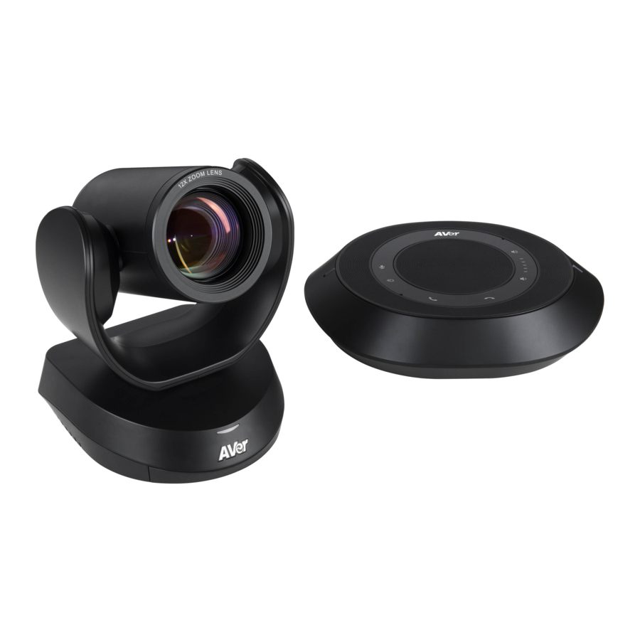
Package Contents Power Adapter & Camera Unit Speakerphone Unit Remote Control Power Cord* USB 2.0 Type-B to Speakerphone 3.5 mm Audio L-Mount Screws for Type-A Cable (5m) Cable (10m) Cable (0.9m) Brackets Mount M4 x8mm (x2) 1/4”-20 L=7.5mm (x2) Drilling Paper QR Code Card 46.00[1.81] Ø5.50[Ø0.22]... -
Page 10: Product Introduction
Product Introduction Overview 3 4 5 6 7 Status LED USB3.1 Type B Port Power on: Blue light RS232 In/Out Port Standby: Orange light DC 12V Power Jack IR Sensor Ethernet Port Speakerphone Port (Blue cable) Kensington Lock 9 1011 12 Speakerphone Port Phone In Port (Red Cable, for extended... -
Page 11: Expansion Speakerphone/Microphone Connection
Expansion Speakerphone/Microphone Connection There are 2 types of expansion solutions that can be extended from the VC520 Pro2 speakerphone. Please purchase the expansion speakerphone and/or microphone directly from AVer or an AVer reseller. Expansion Speakerphone Requirements: VC520 Pro2 Firmware version: 7200.00 or later FONE540 Firmware version: 7000.44 or later... -
Page 12: Phone In Connection
Phone In Connection Users can connect a mobile phone to the Phone in port on the speakerphone as a hands-free speaker. When the device connects with the speakerphone, the icon will light up in blue. Touching the icon will temporarily disconnect the connection of the device with the speakerphone; touching icon again will resume the connection. -
Page 13: Audio Signal Receive Range
Audio Signal Receive Range The best distance for the speakerphone to receive audio signal is within 7.5ft (2.3m) in radius. When connecting two or more speakerphones, the distance between the speakerphones must be 9ft (2.7m). -
Page 14: Speakerphone Led Indicator
Speakerphone LED Indicator Button LED Indicator Status White light Adjust the volume up and down. When adjusting the volume up and down, the volume LED indicator will light up in blue. White/Blue light Touch to mute/un-mute the speakerphone volume. In mute status, the LED indicator will light up in red. -
Page 15: Remote Control
Remote Control Name Function 1. Camera Select One remote can control up to 3 AVer VC/CAM/VB series cameras. You can use AVer PTZApp 2 to set numbers associated with each camera, and then select which camera you would like to control using the remote. - Page 16 4. OSD Menu To call out OSD menu. Not support for VC520 Pro2 5. Zoom In/Zoom Out Increase/Decrease the camera zoom. The Preset button on the remote Preset serves 2 functions.
- Page 17 8. Brightness - Decrease the brightness. 9. Call/answer Answer a call or start a call. 10. Enter To confirm selection. Not support for VC520 Pro2 11. Mute/Un-mute Mute/Un-mute the speakerphone. Speakerphone 12. Volume Up/Down Adjust volume up or down. 13. Preset Hot Key Press to move the camera to the preset position the user has set.
-
Page 18: Installation
Installation Device Connection Connect the camera to power outlet. Power cord Power adapter Connect the camera to the speakerphone using the included compatible cable. Speakerphone cable [Notes] The speakerphone port of the camera and the camera port of the speakerphone are both marked in blue. - Page 19 [Notes] Use the USB 2.0 cable included in the package. VC520 Pro2 has the USB 3.1 port which is USB 2.0 compatible. Maximum resolution/fps for USB 2.0 and USB 3.1 ports are shown below. M-JPEG/fps...
-
Page 20: Rs232 Connection
RS232 Connection Camera RS232 Port Pin Definition Mini DIN9 Function I/O Type Signal Description PIN # Output Data Terminal Ready Input Data Set Ready VISCA IN Output Transmit Data Input Receiver Data Output Data Terminal Ready Input Data Set Ready VISCA OUT Output Transmit Data... - Page 21 Computer/Keyboard Controller and Camera Connection Direct Connection If users don’t buy AVer RS232 adaptor cable, please refer to the pin connection shown below. Mini DIN9 to DB9 cable Camera controller Camera Camera controller or PC (Mini DIN9) (DB9) 1. DTR (IN) 1.
- Page 22 Use the RS232 mini DIN9 to mini DIN8 cable (Sold separately. Please purchase from AVer.). Users can purchase AVer RS232 min DIN9 to mini DIN8 adaptor cable* to connect with Computer or keyboard/controller. * RS232 mini DIN9 to mini DIN8 cable (PN: 064AOTHERCDC) ** Mini DIN8 to D-Sub9 (DB9) cable (PN: 064AOTHERBPK) is an optional item.
- Page 23 *RS232 mini DIN9 to mini DIN8 Cable Pin Definition Mini DIN9 Connect to AVer camera Mini DIN8 (IN) Connect to next camera Connect to camera controller or PC Mini DIN8 (OUT) Mini DIN8 Pin Definition...
- Page 24 Camera Cascade Connection Direct Connection If users don’t buy AVer RS232 adaptor cable, please refer to the pin connection shown below for cascading cameras. Total can connect up to 7 cameras. Mini DIN9 Cable Mini DIN9 Cable Mini DIN9 Cable...
- Page 25 Connect camera with AVer mini DIN9 to mini DIN8 adaptor cable. Connect the mini DIN8 female side to male mini DIN8 Visca cable (Users have to buy it in the market) and then connect AVer mini DIN9 to mini DIN8 adaptor cable again to connect to next camera.
-
Page 26: Wall Mount Installation
Wall Mount Installation 1. Use the drilling paper included in the package to drill the holes in the wall where the user wants to mount the camera. 46.00[1.81] Ø5.50[Ø0.22] 51.00[2.01] P/N: 303AU340-AGR 2. Use the screws (not included) to secure the L-mount bracket A on the wall. Screw For Cement wall: M4 x20mm self-tapping screws (x4) + Plastic conical anchor For Wooden wall: M4 x20mm self-tapping screws (x4) - Page 27 3. Then, assemble the L-mount brackets A + B with screws (included in package). Screw: M4 x8mm (x2) 4. After assembling the L-mount brackets, use the screws (not included) to secure the L-mount bracket B on the wall. Screw For Cement wall: M4 x20mm self-tapping screws (x2) + Plastic conical anchor For Wooden wall: M4 x20mm self-tapping screws (x2)
- Page 28 5. Pass the cables through the hole on the L-mount brackets and connect the cables to corresponding connection ports. 6. Use the remaining screws (included in package) to secure the camera on the L-mount brackets. Screw: 1/4”-20 L=7.5mm (x2)
-
Page 29: Operating The Camera
PTZApp 2, refer to the PTZApp 2 section in this user manual. Make a Connection through the Browser VC520 Pro2 has an Ethernet port for IP streaming and allows administrators to remotely control and set up the camera via an internet access. Moreover, VC520 Pro2 also supports RTSP and RTMP functions. - Page 30 Click weblink icon ( to launch Chrome page. Please enter the password (default password is aver4321). User will be asked to set a new account and password. (Please enter AVer PTZApp2 software to reset password back to default while password is forgotten.) After editing IP address, user can access web settings of the camera with only Ethernet cable connection.
- Page 31 * For information on how to install and use the PTZApp 2, refer to the PTZApp 2 section in this user manual. ** To support IP address changes in groups, user can download AVer IP Finder app. 1. Download the IP Finder from https://www.aver.com/download-center...
-
Page 32: Web Settings
Web Settings VC520 Pro2 supports Ethernet connection; users can enter the IP address into the web browser to connect to the camera for detail settings. First Time Login To find the IP address of the camera, please refer to “Make a connection through the Browser”... - Page 33 Live Screen Operation User can control the camera direction, zoom in/out, and preset selection. [Notes] The system will force the previous login to log out, when there is a second login. If the web page is idle without any request for more than 4 hours, user will be log out. The resolution of live screen is 480p/5fps.
-
Page 34: Set Up The Preset
Set Up the Preset User can set 10 preset positions. In live screen, use mouse to scroll up or down and click the preset number frame (0~9). Use ▲ , ▼ , , and zoom in/out buttons to adjust the camera screen view to desired position. Select “Set Preset”... -
Page 35: Select The Preset Position
Select the Preset Position Preset positions need to be set. Use mouse to scroll up or down to select the preset. Select the preset user wants. The live screen will move to the preset screen view. Camera Settings The video icon is to turn on camera live view while doing any settings. -
Page 36: Tracking Mode
Tracking Mode Select Setting > Camera > Tracking Mode > Off, Manual Frame, Auto Frame, or Preset Framing. Off: Tracking mode is disabled. Manual Frame: User one-click SmartFrame button and camera will adjust view angle to fit all participants in screen for once. - Page 37 Overlap area [Note] VC520 Pro2 frames people in masks or any facial profile up to 7~10 meters away!
-
Page 38: Framing Speed
Framing Speed Select Setting > Camera > Framing Speed > Slow Speed, Middle Speed, or High Speed (default). When in auto framing or preset framing mode, camera will automatically frame people if they stand still without moving for 1~5 seconds. ... -
Page 39: Smart Frame Preset Point
Smart Frame Preset Point Select Setting > Camera > Smart Frame Preset Point > Default(Center of the screen) or Preset0 ~ Preset9. The default is the central of the image screen. Choose a preset point so that camera can detect participants from the wide view of the assigned preset area direction. -
Page 40: Auto Focus
Auto Focus Set auto focus mode. Select Setting > Camera > Auto Focus > PTZ or Continuous. PTZ: By clicking the button (such as pan, tilt, or zoom in/out) to adjust focus once. Continuous: The camera will adjust the focus when the objects have moved. Home Position Every time when powering on the camera, it will turn to this position. -
Page 41: Sleep Position
Sleep Position When the camera idles for certain period, it will enter sleep mode and go to the sleep position. Please set up sleep timer to enable sleep mode. Select Setting > Camera > Sleep Position > Factory Downside Position or Preset 9. Sleep Timer Set the camera idle time to enter sleep mode. -
Page 42: On Screen Menu
On Screen Menu Enable/disable on screen display status information. For instance, when it is at auto frame mode, it will appear “Auto framing” on the bottom of the screen. If you don’t want to see the words, please select Off. Select Setting >... -
Page 43: Save Preset
Save Preset Enable/disable “save preset” function. In some cases, in order not to let end-users change preset points, IT guys can lock “save preset” function by switch this function off. When it’s off, user can’t save preset points via IR remoter, Hot key, VISCA, and webpage. Select Setting >... -
Page 44: Image Settings
Image Settings Image Flip If the VC520 Pro2 is installed in the upside down position, please enable the "Flip". Select Setting > Image > Image Flip > Off or On. Image Mirror To mirror the camera image. Select Setting > Image > Image Mirror > Off or On. -
Page 45: True Wdr
True WDR In back light environment, enabling WDR to improve the brightness of image. Select Setting > Image > True WDR > Off or On. The frame rate will be limited to 30fps while WDR is on. If user enables this function in a normal light condition, the image will become over exposure and encounter image blur. -
Page 46: White Balance
White Balance Select the white balance setting for various light conditions or color temperature. Select Setting > Image > White Balance > Auto or Manual. Noise Reduction To reduce the noise from the signal. Select Setting > Image > Noise Reduction > Off, Low, Middle or High. -
Page 47: Brightness
Brightness Adjust the value of brightness. Select Setting > Image > Brightness > 1 ~ 9. Sharpness Adjust the value of sharpness. Select Setting > Image > Sharpness > Off, Low, Middle or High. -
Page 48: Saturation
Saturation Adjust the value of saturation. Select Setting > Image > Saturation > 1 ~ 9. Low Light Compensation Select Setting > Image > Low Light Compensation > Off or On. Please notice that the frame rate will drop to 10~15 fps. -
Page 49: Rs232 Setting
RS232 Setting When VC520 Pro2 connects with PTZ camera controller through the RS232 port, please setup ADDR, Baud Rate, Protocol, and Visca Over IP settings. Select Setting > RS232. -
Page 50: Video Format Settings
Video Format Settings H.264 Profile While in live broadcasting, user can choose preferable profile to get best streaming quality. Select Video Format > H.264 Profile > Baseline Profile or High Profile. -
Page 51: Ip Stream Resolution
IP Stream Resolution Set up the resolution for IP stream. Not supported for USB video stream. Select Video Format > IP Stream Resolution only (not for adjusting USB video stream) > 1080P, 720P, 480P, or 360P. Please notice that if USB streaming (VC software side) is already in use at 1080p/30fps, the IP streaming resolution (RTSP) will be limited to 720p/30fps. -
Page 52: Frame Rate
Frame Rate Set up the frame rate value. Select Video Format > Frame Rate > 60 FPS, 30 FPS, or 15 FPS. Bit Rate Set up the bit rate value. Select Video Format > Bit Rate > Auto, 512 Kbps, 1 Mbps, 2 Mbps, 4 Mbps, 8 Mbps, 16 Mbps, or 32 Mbps. -
Page 53: Rtsp
RTSP To use RTSP player connecting to the camera, please enter the RTSP URL which displays on the web in your application such as VLC, PotPlayer or Quick Time. Select On to enable RTSP function. - Page 54 Change RTSP Password 1. Select Video Format > RTSP > Change RTSP Access Password. 2. Enter the new password. 3. Select Change to save the new password.
-
Page 55: Rtmp
RTMP Setup for uploading the camera’s live view to the broadcasting platform (e.g. YouTube). Select Video Format > RTMP. 1. Locate the RTMP server URL and stream key from the broadcasting platform and enter in Server URL and Stream Key fields. 2. -
Page 56: Network Settings
Network Settings DHCP Enable/disable DHCP function. Select Network > DHCP > Off or On. -
Page 57: Static Ip
Static IP Assign a fixed IP address to the camera. Please turn off the DHCP function. 1. Select Network > Static IP. 2. Click pencil icon and enter the IP Address, Gateway, NetMask, and DNS in the corresponding fields. 3. Select Confirm to complete the setting. -
Page 58: System Settings
System Settings Language Select the language of the system. Select System > Language > English, Traditional Chinese, or Japanese. -
Page 59: Firmware Update
Update the camera’s firmware. Select System > FW Update > Auto Update or Manual Update. Auto Update: The system will check firmware version from AVer server and request to update. Manual Update: To update the firmware from specific location. -
Page 60: Factory Default
Factory Default Reset the camera back to factory default setting. 1. Select System > Factory Default > Reset. 2. User can choose to keep current IP address or back to default. 3. Select Continue to reset back to factory default. [Note] When factory default is activated, the password of Webpage login will not be set to default. -
Page 61: Camera Reboot
Camera Reboot Restart the camera manually. 1. Select System > Camera Reboot > Reboot. 2. Select Continue to reboot the camera. -
Page 62: Change Password
Change Password Change the web login password. The default password is aver4321. 1. Select System > Change Password > Change WEB Access Password. 2. Enter the old account and password. Select Continue. 3. Enter the new account and password. Select Continue to save the new setting. 4. -
Page 63: Ssl Certificate
SSL Certificate Import the SSL certificate from specific location. 1. Select System > SSL Certificate > Import. 2. Select the type by clicking “+”. 3. Direct the file location. 4. Select Import. -
Page 64: Date Format
Date Format Select the date format. Select System > Date Format > yyyy-mm-dd, mm-dd-yyyy, or dd-mm-yyyy. Time Format Set up the time format. Select System > Time Format > 24-Hour or 12-Hour. -
Page 65: Time Correction Mode
Time Correction Mode Adjust time automatically or manually. Select System > Time Correction Mode > Auto or Manual. Auto: The system time will be set by NTP server on the network. Click the pencil icon of NTP Server and enter the IP address of NTP server. Select the Time Zone. Select NTP Update to save setting. - Page 66 Manual: User can set up time manually. Click the pencil icon and enter the Year, Month, Day, Hour, and Minute. Select Confirm to save the settings.
- Page 67 Information Display the information of Model Name, Firmware Version, Serial Number, IP Address, and MAC Address. Select System > Information.
-
Page 68: Audio Settings
Audio Settings Noise Suppression It is to reduce ambient noise. Select Audio > Noise Suppression > Off or On. When enabling the noise suppression function, please set value of noise suppression (1~40). -
Page 69: Automatically Gain Control
Automatically Gain Control Enable/disable the auto gain control. It is to control ambient sound level and maintain a suitable output, despite variation of the one at the input. Select Audio > Automatic Gain Control > Off or On. Echo Cancellation Enable/disable echo situation. -
Page 70: Keyboard Noise Suppression
Keyboard Noise Suppression Enable/disable keyboard noise reduction. Select Audio > Keyboard Noise Suppression > Off or On. -
Page 71: Phone In Jack
Phone In Jack Set Phone in input source. Select Audio > Phone In Jack > Phone In, 3.5mm External Microphone Only, or 3.5mm External Microphone Mix In. Phone In: When the mobile phone is connecting to Phone in port, please select “Phone In” option. ... -
Page 72: Ptzapp 2
PTZApp 2 In PTZApp 2, user can change the IP address setting of VC520 Pro2, configure the parameters of the camera, set up AI tracking functions and some advanced image and audio settings, pan, tilt, and zoom the camera. Install PTZApp 2 Please go to https://www.aver.com/download-center... - Page 73 Choose “USB devices” and connect VC520 Pro2 to PC/laptop with USB cable When the camera is detected, the product card will show up. Set up IP address. The camera default IP address is 192.168.1.168. Click pencil icon ( ) to edit IP address.
- Page 74 Language: Select desired language and click the check icon to confirm the selection. Hotkey Control: User can control the camera by using keyboard. This is a general list for all Aver USB Cameras. Backlight control equals to WDR function in VC520 Pro2.
- Page 75 Information: Click the drop-down triangle icon to review the information of camera. To minimize the information, click the triangle or the bottom area of the information icon. Camera: Click the camera icon to view the camera live view. IP address is displayed as well. Click the X icon to close the camera live view.
- Page 76 Full Screen: PTZApp 2 can switch to full screen mode. Click “ ” icon and video screen will switch to full screen mode. In full screen mode, user can use direction panel to control camera direction. Click “ ” icon to go back to normal screen view. The resolution of full screen mode is 1080p.
- Page 77 People Count and Stream Interval: Click the icon to show people count number and stream interval. Click the icon to hide the stream interval. Control Panel: To control the camera direction, zoom in and out, and to enable/disable the “Smart Framing”...
- Page 78 Setting: Click “Setting” button to setup parameters of the camera and speakerphone. Click arrow icon to leave the Setting page. PTZ Control: Use control panel to setup preset positions. Since most of operations are the same as web page, refer to Setup the Preset section (page 26) for detailed setup.
- Page 79 The following items are different from web page in System. I/O Port: Except USB port, user can enable or disable all I/O ports. Trouble Shooting: Click Start and Output to output log to save in local PC. Test Speakerphone: Click Start and Start to check the speakerphone status. It will require user to record a short message and play it back to ensure the speakerphone is working.
- Page 80 10. Click the icon to display the connected devices to the VC520 Pro2. 11. PTZApp 2 Minimize: Minimize the app to system tray. To quit the application, right-click the icon on the system tray and select “Quit”. If you can’t launch PTZApp 2 right after installation, please also check here and see if it is...
-
Page 81: Install Ezlive
Install EZLive Please go to http://www.aver.com/download-center to download the AVer EZLive software. After downloading, double-click on the file and follow the on-screen instructions to complete the installation. Use EZLive During a video call, EZLive can help user to do: (1) Camera ePTZ (2) Volume control for the speaker connected (3) Capture camera’s still images...
Need help?
Do you have a question about the VC520 Pro2 and is the answer not in the manual?
Questions and answers