Table of Contents
Advertisement
Quick Links
EH Series
Dock Leveler
Owner's/User's Manual
Poweramp • Division of Systems, LLC • W194 N11481 McCormick Drive • Germantown, WI 53022
800.643.5424 • fax: 262.255.5917 • www.poweramp.com • techservices@poweramp.com
Printed in U.S.A.
Manual No. 4111-0004
© 2021 Systems, LLC - All Rights Reserved
Apr. 2021
Advertisement
Table of Contents

Related Manuals for SYSTEMS Poweramp EH Series


Summary of Contents for SYSTEMS Poweramp EH Series
- Page 1 EH Series Dock Leveler Owner’s/User’s Manual Poweramp • Division of Systems, LLC • W194 N11481 McCormick Drive • Germantown, WI 53022 800.643.5424 • fax: 262.255.5917 • www.poweramp.com • techservices@poweramp.com Printed in U.S.A. Manual No. 4111-0004 © 2021 Systems, LLC - All Rights Reserved...
-
Page 2: Table Of Contents
Table of Contents Page Precautions Recognize Precautionary Information ..........1 General Operational Precautions ............1 Operational Precautions ..............2 Safety Decals ..................4 Placard ....................5 Owner’s User’s Responsibilities ............6 Introduction General Information ................8 Component Identification ..............9 Installation Installation Precautions .............. -
Page 3: Precautions
WARNING: This product can expose you to chemicals including lead, which are known to the State of California to cause cancer or birth defects or other reproductive harm. For more information go to www.P65Warnings.ca.gov 4111-0004 — Apr. 2021 © 2021 Systems, LLC... -
Page 4: Operational Precautions
Keep hands and feet clear of pinch points. Avoid putting any part of your body near moving parts. Make sure lip overlaps onto transport vehicle bed at least 4 in. (102 mm). Keep a safe distance from both side edges. 4111-0004 — Apr. 2021 © 2021 Systems, LLC... - Page 5 Do not overload the dock leveling device. Do not operate any equipment while under the influence of alcohol or drugs. Do not leave equipment or material unattended on dock leveling device. 4111-0004 — Apr. 2021 © 2021 Systems, LLC...
-
Page 6: Safety Decals
1751-0731 Rev A 1751-0731 Serial Tag Left Platform Side File Name: 1751-0731 Rev A Decal Size: 5.05 x 2.40 Right Platform Side Right Platform Side Decal Placement for H Series Figure 2 4111-0004 — Apr. 2021 © 2021 Systems, LLC... -
Page 7: Placard
WARNING: CANCER AND REPRODUCTIVE HARM NOTE: If equipped, Pressing E-STOP button will stop platform from lowering. 1751-0874 Rev D www.P65Warnings.ca.gov 1751-0874 4111-0004 — Apr. 2021 © 2021 Systems, LLC... -
Page 8: Owner's User's Responsibilities
Effective operator training should also focus on 4111-0004 — Apr. 2021 © 2021 Systems, LLC... - Page 9 Also, whenever possible, air-ride suspension systems should have the air exhausted prior to performing said loading and unloading operations.
-
Page 10: Introduction
To illustrate which connections are to be made in the 40,000 lb (18 144 kg) field at installation, electrical drawings are included 45,000 lb (20 412 kg) with each order or by contacting Systems, LLC 50,000 lb (22 680 kg) Technical Services. 60,000 lb (27 216 kg) -
Page 11: Component Identification
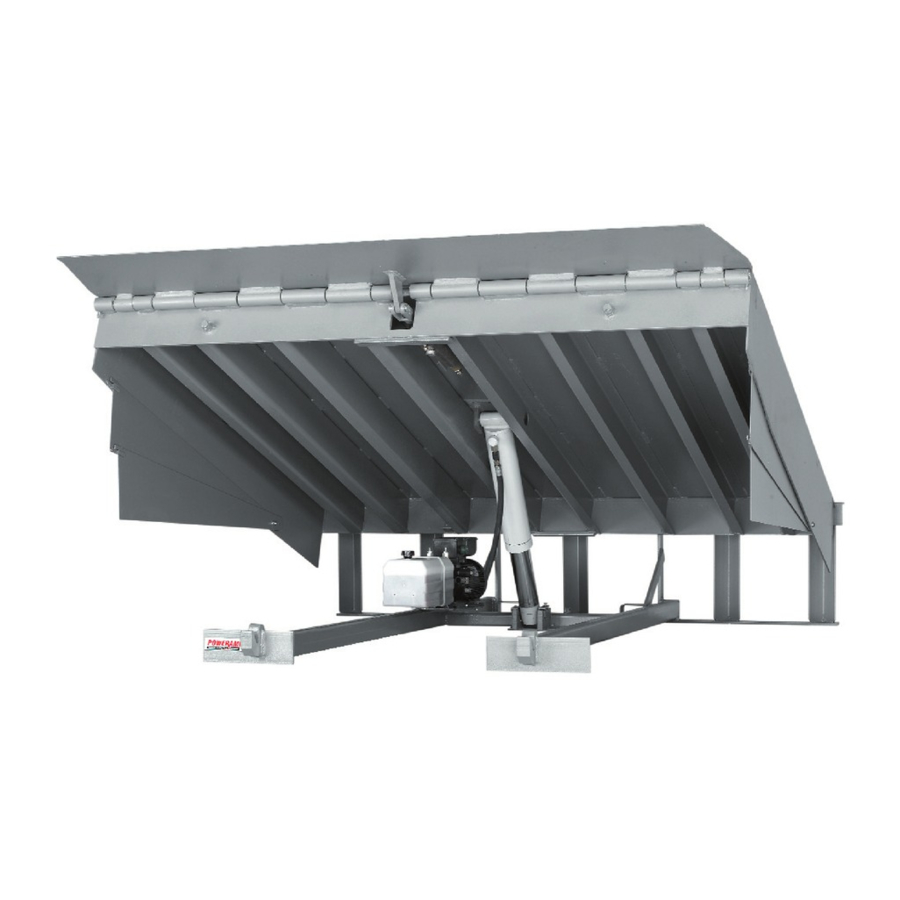
H — Maintenance Prop Lock-Out L — Lip Keepers (2 used) C — Platform F — Platform Cylinder J — Maintenance Prop M — Control Box* * Control box appearance may vary depending on options. 4111-0004 — Apr. 2021 © 2021 Systems, LLC... -
Page 12: Installation
Always keep a fire extinguisher of the proper type nearby when grinding or welding. Only trained installation professionals with the proper equipment should install this product. 4111-0004 — Apr. 2021 © 2021 Systems, LLC... - Page 13 INSTALLATION This page intentionally left blank. 4111-0004 — Apr. 2021 © 2021 Systems, LLC...
-
Page 14: Prepare Pit
Take measurements at dock floor level and at pit floor level. If any measurement is off by more than 1/8 in. (3.18 mm), contact Systems, LLC Technical Services before proceeding. 3. Make sure the field junction box for the dock leveler is at the correct location per pit diagrams. -
Page 15: Prepare Dock Leveler
(i.e., hoist or fork truck) having the ANGULAR: This print is the property of Systems, LLC and repre of use and/or manufacture and/or sale. Possession o such permission to be granted only by written author and shipping bands (B) around the platform lip and appropriate lifting capacity and reach. -
Page 16: Install Dock Leveler
Rear Vertical Supports) F— Rear Pit Curb Angle K— Distance (Dock Floor-to- N— Dock Leveler Frame C— Shim Location (Under G— String Pit Floor) P— Lip Keeper Shim (as Maintenance Prop) required) 4111-0004 — Apr. 2021 © 2021 Systems, LLC... - Page 17 (A). Note: Hoist cylinder and maintenance prop will be 4. Put a 1/4” (6.6 mm) thick shim underneath each shimmed later in the install process. lip keeper (C). 4111-0004 — Apr. 2021 © 2021 Systems, LLC...
- Page 18 (if equipped) will not bind during dock leveler operation. 11. If leveler cannot be squared and/or made level as instructed in steps 8-10, contact Systems, LLC Technical Services. 4111-0004 — Apr. 2021 © 2021 Systems, LLC...
- Page 19 16. If binding occurs, lower the platform. Reposition leveler and/or add or remove shims as necessary. Slowly raise platform again. If platform still binds, contact Systems, LLC Technical Services for further instructions. If the platform is raised using an external lifting device or the hydraulic system is opened to atmosphere, air will enter into the hydraulic system.
- Page 20 Make sure the platform is properly supported in the raised position before entering the pit to finish weld the shims. 4111-0004 — Apr. 2021 © 2021 Systems, LLC...
- Page 21 Offset w/Load Over Center (Acceptable) 22. Install the dock bumpers as required. 23. Proceed to “Install Control Panel and Wiring” on Page 20. Offset w/Load Over Edge Straight (Not Acceptable) (Not Acceptable) Figure 13 4111-0004 — Apr. 2021 © 2021 Systems, LLC...
-
Page 22: Install Control Panel And Wiring
Systems, LLC is not responsible for any Where indicated, all components must be connected damage due to moisture collecting inside the control... - Page 23 Danfoss Control Panel Wiring (3-Phase) Jumper wire (L1 to 95) Jumper wire (A1 to L2) L o a d i n g D o c k E 4111-0004 — Apr. 2021 © 2021 Systems, LLC...
-
Page 24: Placard Installation Instructions
WARNING: CANCER AND REPRODUCTIVE HARM NOTE: If equipped, Pressing E-STOP button will stop platform from lowering. www.P65Warnings.ca.gov 1751-0874 Rev D (Enlarged for clarity) Figure 15 A—Control Box B— Placard C— Nylon Cable Tie D— Conduit 4111-0004 — Apr. 2021 © 2021 Systems, LLC... -
Page 25: Put New Dock Leveler Into Service
Note: If an excessive transition exists between the dock floor and leveler and/or lip does not contact both lip keepers evenly, contact Systems, LLC Unless the dock leveler is equipped with a tethered Technical Services for further instructions. -
Page 26: Operation
Make sure platform lip rests on the transport vehicles bed with at least 4 in. (102 mm) of overlap. Maintain a safe distance from side edges of leveler during the loading/unloading process. 4111-0004 — Apr. 2021 © 2021 Systems, LLC... - Page 27 OPERATION This page intentionally left blank. 4111-0004 — Apr. 2021 © 2021 Systems, LLC...
-
Page 28: Ramp Loading/Unloading Instructions
4 in. (102 mm) of lip contacting the transport vehicle bed. See Figure 16. Figure 16 5. Proceed with loading or unloading the transport vehicle. 4111-0004 — Apr. 2021 © 2021 Systems, LLC... -
Page 29: End Loading/Unloading Instructions
5. Raise the platform by pressing and holding the RAISE button until the lip extends just enough to clear the lip keepers, then release the RAISE button. 6. Allow the platform to drift down to the full below- dock position. 4111-0004 — Apr. 2021 © 2021 Systems, LLC... -
Page 30: Optional Equipment
E-Stop is released! Always make sure the platform is properly supported in the raised position before entering the pit or going under the dock leveler. 4. Continue operating dock equipment as needed. 4111-0004 — Apr. 2021 © 2021 Systems, LLC... -
Page 31: Maintenance
A — Lock Out Device C — Maintenance Prop E — Lip plate ANGULAR: This print is the property of Systems, L B — Tag Out D — Header plate patent and other rights, including exclu not convey any permission to reproduc... -
Page 32: Periodic Maintenance
Use of fluids that do not have equivalent specifications to those in the preceding list will result in abnormal operation of the dock leveler and voiding of warranty. 4111-0004 — Apr. 2021 © 2021 Systems, LLC... - Page 33 Yearly Maintenance Failure to properly lubricate the dock leveler will • Complete Quarterly Maintenance. cause abnormal operation of the leveler. • Change hydraulic oil (may be required more often depending upon conditions). 4111-0004 — Apr. 2021 © 2021 Systems, LLC...
-
Page 34: Adjustments
Valve Adjustments (Monarch/Bucher Powerpacks, 9/2010-present) Valve location varies by production date Figure 25 A— S1 Valve C— RV1 Valve E— Breather Cap G— To Lip Cylinder B— S2 Valve D— NV1 Valve F— To Hoist Cylinder 4111-0004 — Apr. 2021 © 2021 Systems, LLC... - Page 35 Keeps Lip from collapsing until it is below dock. This and should not require additional adjustments in the valve is not adjustable. If lip malfunctions, cleaning field. Consult Systems, LLC Technical Services if or replacement may be required. minor adjustments do not result in proper operation.
-
Page 36: Valve Adjustments (Hoke/Kti Powerpacks)
G—To Hoist Cylinder B— S2 Valve D— 2W NO Spool Valve F— Breather Tube/Fitting H—To Lip Cylinder Note: Not pictured (on the bottom of the valve body) are the RV2 and PO Check Valves 4111-0004 — Apr. 2021 © 2021 Systems, LLC... - Page 37 Fluid should flow through the NV1 valve. If and should not require additional adjustments in the you hear the motor spinning backwards, or Leveler field. Consult Systems, LLC Technical Services if and/or Lip may dropping prematurely adjust S1 minor adjustments do not result in proper operation.
-
Page 38: Valve Adjustments (Bucher 60K Or 10' Levelers)
ADJUSTMENTS Valve Adjustments (Bucher Powerpacks - 60K or 10’ Levelers) Figure 27 A— Needle Valve B— Sequence Valve C— RV1 Valve 4111-0004 — Apr. 2021 © 2021 Systems, LLC... - Page 39 Decrease and should not require additional adjustments in the down speed by turning thumb wheel clockwise. field. Consult Systems, LLC Technical Services if Tighten jam nut after adjustment. minor adjustments do not result in proper operation.
-
Page 40: Adjust Auto Return To Dock (Artd)
(H) that can be used for diagnosing and adjusting the switch. Note: Some proximity switches have an indicator light at the back of the housing and some have the light at the side of the housing. 4111-0004 — Apr. 2021 © 2021 Systems, LLC... - Page 41 Make small adjustments, then operate the dock leveler to check results. Do this until satisfied with the ARTD operation. Note: Use the illustrations on page 40 to assist in fine tuning and/or diagnosing the ARTD operation. 4111-0004 — Apr. 2021 © 2021 Systems, LLC...
- Page 42 • Target not in the sensing area of proximity switch. • Proximity switch OFF (open, no signal sent to control panel). • Proximity switch indicator light is OFF. • Platform stays at this position unless the operator activates the leveler. 4111-0004 — Apr. 2021 © 2021 Systems, LLC...
-
Page 43: Adjust Leveler Stored Switch
4. Verify that the target will not contact the sensor face, or damage to the sensor may occur. Figure 35 4111-0004 — Apr. 2021 © 2021 Systems, LLC... -
Page 44: Troubleshooting
If voltage is present and starter or relay does not (single-phase) not energize, replace starter or relay. energizing. • If voltage is not present, check all components in series with the starter or relay coil. 4111-0004 — Apr. 2021 © 2021 Systems, LLC... - Page 45 ARTD only: Platform does not Faulty proximity switch. Replace switch. automatically return to the cross-traffic position or operates abnormally. Loose/corroded wire Repair or replace wires and connections as connections or broken wire. necessary. 4111-0004 — Apr. 2021 © 2021 Systems, LLC...
- Page 46 Check for visible obstructions that could cause Dock leveler binds. binding. Remove obstructions. If no obstructions found, contact Systems, LLC Technical Services. Platform does not rise. Pump operates in Increase pressure relief. Contact Systems, LLC pressure relief mode.
- Page 47 Replace hydraulic fluid, see pages 30-31 for proper fluid. fluid level and type. If additional troubleshooting assistance is required, contact Systems, LLC Technical Services with equipment serial number or customer order number (CO#). Technical Service at 800-643-5424 or techservices@loadingdocksystems.com 4111-0004 — Apr. 2021...
-
Page 48: Parts
230v 3-Phase Danfoss Control Box (MTR 3627E) 7141-0271 460v 3-Phase Danfoss Control Box (MTR 3627F) * Provide dock leveler serial number, voltage, phase, and options when e-mailing, calling or faxing controller orders 4111-0004 — Apr. 2021 © 2021 Systems, LLC... -
Page 49: Optional Electrical Parts
J-Box, Standard (4 x 4 in. Metal Box) 2751-0042 J-Box, Cold Weather (5 x 5 in. Plastic Box) * Provide dock leveler serial number, voltage, phase, and options when e-mailing, calling or faxing controller orders 4111-0004 — Apr. 2021 © 2021 Systems, LLC... -
Page 50: Frame And Platform
PARTS Frame and Platform Detail A Detail A 4111-0004 — Apr. 2021 © 2021 Systems, LLC... - Page 51 Maintenance Prop Rod 9201-0006 Prop Pin and Clip 8432-____ Lip Keeper AR = As Required 1 Provide dock leveler serial number, platform size, and lip size when e-mailing, calling or faxing orders. 4111-0004 — Apr. 2021 © 2021 Systems, LLC...
-
Page 52: Hydraulic Components
This print is the property of Systems, Inc. and represents a proprietary article in which Systems, Inc. retains any and all patent and other rights, including exclusive rights of use and/or manufacture and/or sale. Possession of this print does not convey any permission to reproduce, print or manufacture the article or articles shown therein, such permission to be granted only by written authorization signed by an officer or other authorized agent of Systems,Inc. - Page 53 Provide length and diameter of hose when e-mailing, calling or faxing orders. Provide length of lip cylinder when e-mailing, calling or faxing orders. Provide dock leveler serial number, voltage, and phase when e-mailing, calling or faxing orders. 4111-0004 — Apr. 2021 © 2021 Systems, LLC...
-
Page 54: Powerpack Assembly
PARTS Monarch/Bucher Powerpack Assembly (9/2010-present) Motor Pump Valve Block Valve location varies by production date 4111-0004 — Apr. 2021 © 2021 Systems, LLC... - Page 55 T1 T2 T3 Provide dock leveler serial number and type of installation when e-mailing, calling or faxing orders. Provide dock leveler serial number, voltage, and phase when e-mailing, calling or faxing orders. 4111-0004 — Apr. 2021 © 2021 Systems, LLC...
- Page 56 PARTS Hoke/KTI Powerpack Assembly (pre-9/2010) 4111-0004 — Apr. 2021 © 2021 Systems, LLC...
- Page 57 T1 T2 T3 Provide dock leveler serial number and type of installation when e-mailing, calling or faxing orders. Provide dock leveler serial number, voltage, and phase when e-mailing, calling or faxing orders. 4111-0004 — Apr. 2021 © 2021 Systems, LLC...
-
Page 58: Valve Block - Emergency Stop/Lip Out
ANGULAR: This print is the property of Systems, Inc. and represents a proprietary article in which Systems, Inc. retains any a patent and other rights, including exclusive rights of use and/or manufacture and/or sale. Possession of this print not convey any permission to reproduce, print or manufacture the article or articles shown therein, such permissi granted only by written authorization signed by an officer or other authorized agent of Systems, Inc. -
Page 59: Weather Seal
Rear Foam Seal, Self-Adhesive, Pre-Cut, 6.5’ Wide Levelers 0195-0048 Rear Foam Seal, Self-Adhesive, Pre-Cut, 7’ Wide Levelers * Provide dock leveler serial number and size of platform when e-mailing, calling or faxing orders 4111-0004 — Apr. 2021 © 2021 Systems, LLC... -
Page 60: Toe Guards
Screw, HHCS, 3/8-16 x 1.25 2101-0060 Washer, Flat, 3/8” 2101-0040 Locknut, Nylon Insert, 3/8-16 0011-0010 Platform Mounting Tab * Provide dock leveler serial number and size of platform when e-mailing, calling or faxing orders 4111-0004 — Apr. 2021 © 2021 Systems, LLC... -
Page 61: Miscellaneous
(A, B) becomes lost or damaged. Model ___________________________________ Also, write down Systems, LLC’s order number, the Serial No. ________________________________ company that installed the dock leveler, and the original owner’s name. This will all help to identify the specific dock Systems, LLC Order No. -
Page 62: Warranty
Owner/User. In the event of a defect, as determined by SYSTEMS LLC, covered by this warranty, SYSTEMS LLC shall remedy such defect by repairing or replacing any defective equipment or parts, bearing the cost for the parts, labor and transportation.
Need help?
Do you have a question about the Poweramp EH Series and is the answer not in the manual?
Questions and answers