Huawei OptiX RTN 980 Quick Installation Manual
Radio transmission system v100
Hide thumbs
Also See for OptiX RTN 980:
- Quick installation manual (44 pages) ,
- Quick installation manual (44 pages)

Related Manuals for Huawei OptiX RTN 980


Summary of Contents for Huawei OptiX RTN 980
- Page 1 OptiX RTN 980 Radio Transmission System V100 IDU Quick Installation Guide for Outdoor Cabinets (APM30H&TMC11H Cabinets) Issue: 01 Date: 2018-10-30 HUAWEI TECHNOLOGIES CO., LTD.
- Page 2 Notice The purchased products, services and features are stipulated by the contract made bet ween Huawei and the customer. All or part of the products, services and features described in this document may not be within the purchase scope or the usage scope. Unless otherwise specified in the contract, all statements, information, and recommendations in this document are provided "AS IS"...
- Page 3 Huawei. The safety precautions in this document are relevant only to Huawei products. Huawei is not liable for any consequence that results from violation of universal regulations for safety operations and safety codes on design, production, and equipment use.
- Page 4 Instructions and Precautions for Handling Boards CAUTION Do not hold a board without hand protection. Wear an ESD wrist strip or ESD gloves before handling a board. Wearing ESD gloves Wearing an ESD strip Holding a board without hand protection CAUTION Hold the front panel of a board with hands.
- Page 5 Precautions for Handling the Toggle Lever Switch • Position and description of the toggle lever switch O: OFF CAUTION Turn the toggle lever switch only after gently pulling it out. I : ON NOTE A dual-channel IF board does not have a toggle lever switch.
-
Page 6: Tools For Installation
Tools for Installation Level Phillips screwdriver Flat-head screwdriver Adjustable Wrench Long measuring tape COAX crimping tool Socket w rench Torque w rench Hex key Wire clippers RJ45 crimping tool Wire stripper Diagonal pliers Cold press pliers Needle-nose pliers Multimeter Bayonet w rench Combination pliers File Heat gun... -
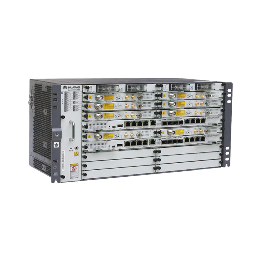
Page 7: Introduction To The Equipment
Introduction to the Equipment Introduction to the RTN 980 Front View Based on different board configurations, the positions of the actual IDU ports may be different from the positions shown in the figure. Oblique View Side View... - Page 8 Introduction to the APM30H/TMC11H Cabinet Front View of the APM30H Cabinet Technical Specifications • Dimensions (mm): 700 (H) x 600 (W) x 480 (D) • Ambient temperature: -40°C to +50°C • Sunshine radiation: 1120±10% W/m2 NOTE The exterior of the TMC11H cabinet is the same as the exterior of the APM30H cabinet.
- Page 9 About the Internal Structure of the APM30H and TMC11H Cabinets • Internal Structure of the APM30H Cabinet (AC Power Supply) Fan assembly (internal circulating) * CMUA board HPMI board * PSU module EPS frame PMU module Cable distribution box • Internal Structure of the TMC11H Cabinet (DC Power Supply) Fan assembly (internal circulating) * CUMA board DCDU-03 module...
- Page 10 Installation Scenarios of the Cabinets Installation Scenarios of the APM30H or TMC11H Cabinet Requirements for the Installation Dimensions and Space of the Cabinet (Unit: mm) > 60 Cabinet Cabinet Cabinet > 300 > 300 Maximum 120° > 800 NOTE • The data shown in the figure is not for the concrete pad.
-
Page 11: Installing The Cabinets
Installing the Cabinets Installing the Base Cast a concrete pad. The height of the concrete pad must meet the heat-dissipation and waterproofing requirements of the cabinet. The concrete pad must be 200 mm higher than the ground, and the horizontal error must be less than 5 mm when the pad is cast. - Page 12 Install the expansion bolt assembly. M12x60 bolt Remove the spring washer, Rubber flat washer, and bolt. mallet Spring washer 12 Flat washer 12 Expansion tube Position the base, and then screw the bolt Adjust the base level. with the spring washer and flat washer. Adjust the base level by adding certain pads to the bolts between the base and the concrete pad.
- Page 13 Remove the baffle plates from both sides Remove the baffle pieces from the back of the base (by removing the plate on the of the base. left side as an example). NOTE All the three cable holes on the base can be used for cable layout, depending on the actual requirements.
- Page 14 Securing the Cabinet onto the Base M12x30 (x4) Gasket with an oblong hole Waterproof rubber pad Gasket with an oblong hole NOTE The IBBS200D battery cabinet is considered as an example in the installation. When installing the APM30H, TMC11H, or IBBS200T cabinet, use the same method. Stacking the Two Cabinets (Optional) Remove the two cover plates Remove the four rubber...
- Page 15 Installation Scenarios of the Transmission Equipment Dedicated Outdoor Installation Installing the RTN 980 in the APM30H Cabinet Fan unit NOTE A 1 U space needs to be reserved between the RTN 980 and the heater. Power supply system RTN 980 Heater Installing the RTN 980 in the TMC11H Cabinet Fan unit...
-
Page 16: Installing The Assemblies
Cabinet Sharing-Installing the RTN 980 in the TMC11H Cabinet NOTE DCDU-03 • A 1 U space needs to be reserved between the RTN 980 and the heater. • If the RTN 980 and wirelss transmission equipment need to be installed in one cabinet, the cabinet must be a TMC11H cabinet. - Page 17 If more than 12 E1 signals are transmitted, the UFLP board needs to be replaced with the UELP board. The removed UFLP board needs to be returned to the local representative office of Huawei.
- Page 18 Installing the Heater(Optional) Install the heater. The heater is preferably installed in the bottom If both the SOU and the heater are installed in the 1U space of the cabinet. cabinet, the heater is installed above the SOU. NOTE • When the temperature inside the cabinet is lower than 0°C, the heater starts working. When the temperature inside the cabinet is higher than 15°C, the heater stops working.
- Page 19 Installing and Routing the Cables Installing the PGND Cables Installing the PGND Cables for the Cabinet WARNING NOTE • When installing the PGND cables in the APM30H cabinet, use the same method. • The ground cables and signal cables must be bound separately or must be separated from each other to minimize mutual interference.
- Page 20 Installing and Routing the Power Cables – DC Power Supply Installing the Input Power Cable for the TMC11H Cabinet NEG(-) DC pow er box cover RTN(+) Remove the cover of Install the input power cable. the DC power box. Put back the cover of the DC power box.
- Page 21 Installing the Service Cables for the Equipment Installing E1 Cables INSIDE OUTSIDE INSIDE OUTSIDE UFLP INSIDE OUTSIDE E1 cables for 1xAnea 96/4xDB25 conversion are used. Rubber block 1-16 NOTE For cabinet sharing, the E1 cables need not be connected Cable outlet bags to the SLPU.
- Page 22 Installing IF Cables UFLP INSIDE OUTSIDE Rubber block Cable outlet bags are used in cabinets of Ver. D. O : OFF I : ON CAUTION Do not remove or insert the IF cables when the ODU is powered on. Installing Fibers Binding strap UFLP INSIDE...
- Page 23 Installing Signal Monitoring Cables COM_IN port CMUA board COM IN UFLP INSIDE OUTSIDE CF RCV NMS/COM CLK/TOD1 TOD2 CSHN board TOD2 port NOTE Before installing a signal monitoring cable, remove the cable already connected to the COM_IN port on the CMUA board.
- Page 24 Sealing the Cable Outlet Module Cable Outlet Module NOTE 1: Left cable outlet; 2: Right cable outlet The cable outlet module of TMC11H is the same as that of APM30H. Sealing Method Tighten the cable outlet bags.
- Page 25 Sealing the Cable Holes on the Base Baffle plate Fireproof mud Fireproof mud Baffle plate Fireproof mud PVC corrugated pipe Baffle piece Apply baffle plates to the cable outlets on the base. Apply fireproof mud to the surroundings of the cable outlets on the base. Close the front cover of the base.
-
Page 26: Installing The Batteries
Installing the Batteries Install the batteries. WARNING Before installing the batteries, set the battery circuit breaker labeled BAT to OFF to prevent overcurrent. During the installation of the batteries, apply an insulation sheath to the tool such as the wrench and screwdriver, and do not short-circuit the positive and negative poles of the batteries. -
Page 27: Checking The Installation
Checking the Installation Checking Cabinet Installation What to Check For The layout of the cabinet complies with the engineering designs. The base is installed securely. The deviation of the cabinet is less than 3 mm horizontally and not more than 3 mm vertically. All the bolts are tightened, especially those for electrical connections. - Page 28 Checking Electrical Connections of the Cabinet What to Check For All the self-made PGND cables are copper-based with proper wire diameters. There is no switch, fuse, or short circuit on the cable. According to the wiring diagram of the power system, the PGND cables are connected securely, the AC lead-in cables and cables inside the cabinet are connected properly, and the screws are tightened.
- Page 29 Checking the Power-On Status Checking the Power-On Status NOTE This part describes only the process for checking the pow er-on status of the AC pow er equipment. When checking the pow er-on status of the DC pow er equipment, refer to the process for checking the pow er-on status of the AC pow er equipment. In the case of AC power supply Start Normal statuses of the indicators on the PMU:...
- Page 30 Appendixes Assembling the Power Series 120 Connector 1. Material: power series 120 connector, contact terminal, heat shrink tube, and cable 2. Procedure for assembling the power series 120 connector Strip a part of the jacket off the cable to expose the Route the cable through the heat shrink tube, and conductor with a length of L1.
- Page 31 Assembling the Easy Power Receptacle (Pressfit Type) Connector 1. Material: easy power receptacle (pressfit type) connector, contact terminal, heat shrink tube, and cable 2. Procedure for assembling the easy power receptacle (pressfit type) connector Strip the jacket off the cable based on the scale on Push the sliding block by using a screwdriver until the equipment.
-
Page 32: Replacing The Fuse
Replacing the Fuse Remove the extraction tool. Remove the fuse from the case. Replace the fuse by using the extraction tool. Align the bulge on the extraction tool Fuse with the hole on the fuse. Fuse Remove the fuse by using the extraction tool. - Page 33 Repairing Paint 1. Codes of Color Samples Object Color Name Huawei Color International Color Code Code Cabinets (including the APM30H and TMC11H ) RAL7035 YB026 RAL7035 Base 3010 light grey YB030 Pontone 422U 2. Operation Instructions Polishing If a damaged area is stained or the materials are rusty, polish the damaged area or the rusty materials by using a piece of fine sand paper to remove the stain or rust.
- Page 34 HUAWEI TECHNOLOGIES CO., LTD. Huawei Industrial Base Bantian Longgang Shenzhen 518129 People’s Republic of China www.huawei.com...
Need help?
Do you have a question about the OptiX RTN 980 and is the answer not in the manual?
Questions and answers