Advertisement
Quick Links
DiTrak encoder calibration
software manual
Tools and documentation required to perform encoder calibration
1. RLS DiTrak absolute magnetic encoder website
2. DiTrak encoder data sheet
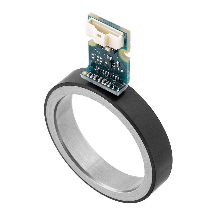
3. RLS DiTrak encoder (one of options)
4. RLS magnetic ring
5. Interconnecting cable between encoder and interface
6. RLS USB PC Interface E201-9B
7. Mechanical mounting setup
8. Ditrak calibration application
Setup
1. Mount the ring and DiTrak encoder according to mechanical specifications listed in DiTrak
Encoder datasheet.
2. Connect encoder to E201-9B interface.
3. Connect E201-9B via USB cable to your computer.
4. Launch the DiTrak calibration application
5. Press "Connect" button – when connected all should lit green, if error occurs it is listed in
command window.
A
associate company
Application note
NBP02_01
Issue 1, 11
June 2018
th
Advertisement

Related Manuals for RLS DiTrak

Summary of Contents for RLS DiTrak
- Page 1 7. Mechanical mounting setup 8. Ditrak calibration application Setup 1. Mount the ring and DiTrak encoder according to mechanical specifications listed in DiTrak Encoder datasheet. 2. Connect encoder to E201-9B interface. 3. Connect E201-9B via USB cable to your computer.
-
Page 2: Application Note
Application note NBP02_01 6. For calibration open tab “Calibration/Settings”. Assure that magnetic ring is rotating at constant speed from 50 to 300 RPM. Choose approximate value of rotating speed. It is not recommended to calibrate outside of rotation speed ranges mentioned above. 7. - Page 3 8. After calibration the results are displayed in a status bar. If calibration was successful Track Error, Phase, Offset and Gain fields will lit green. If they lit orange it means that calibration was successful but the parameters are at limit values.
- Page 4 Application note NBP02_01 Calibration Application Extra Settings 1. Multi-turn position is counted. Encoder position readout: Tab “Position” offers different modes to display the single-turn position (counts, degrees, hexadecimal, binary. Multi-turn is always in counts (shaft turn counter). 2. Rotation direction / Set zero position: current mechanical position can be set as a zero encoder readout by pressing “Set to Zero”...
- Page 5 3. Advanced settings can be found in tab Settings: - Invert all incremental signals separately: A, B and Z signal can be inverted - Resolution: incremental resolution can be set from 4 counts to 262144 in 4 count increments (Note: higher incremental resolution means lower maximum rotation speed) also AB Output Frequency must be set after selecting higher incremental resolution.
- Page 6 New document RLS merilna tehnika d.o.o. has made considerable effort to ensure the content of this document is correct at the date of publication but makes no warranties or representations regarding the content. RLS merilna tehnika d.o.o. excludes liability, howsoever arising, for any inaccuracies in this document.
Need help?
Do you have a question about the DiTrak and is the answer not in the manual?
Questions and answers