Table of Contents
Advertisement
Quick Links
Installation, Operation & Maintenance Manual
CGS supply a range of remote gas detectors including carbon monoxide (CO), natural gas/methane (NG), liquid
petroleum gas (LPG) and also oxygen (O2) that are compatible with our range of Merlin control panels connecting up
to 16 detectors (control panel dependant) per cable run to monitor gas levels/hazards in safe areas.
The information contained within this manual should be referenced for typical installation and operation only.
For specific requirements that may deviate from the information in this manual – contact your supplier.
IOM Iss: 1 05-21
Gas Detector TFT
Addressable Safe Area Fixed Gas Detector
Installation, Operation & Maintenance
Please read this manual carefully and retain for future use.
Merlin Detector-TFT
1
Advertisement
Table of Contents

Related Manuals for CGS TFT

Summary of Contents for CGS TFT
- Page 1 Please read this manual carefully and retain for future use. CGS supply a range of remote gas detectors including carbon monoxide (CO), natural gas/methane (NG), liquid petroleum gas (LPG) and also oxygen (O2) that are compatible with our range of Merlin control panels connecting up to 16 detectors (control panel dependant) per cable run to monitor gas levels/hazards in safe areas.
-
Page 2: Table Of Contents
Installation, Operation & Maintenance Manual Merlin Detector-TFT Contents Important Warning Statements ................... 3 Installation ..........................4 Typical Location & Positioning ......................4 Access & Mounting ..........................5 Internal Board Overview ........................5 Wiring a Detector (GDP2X or GDPX+ Control Panel) ..............6 Creating a Detector Chain ......................... -
Page 3: Important Warning Statements
At the end of their working life, electrochemical sensors for oxygen and carbon monoxide detectors should be disposed of in an environmentally safe manner. Alternatively they can be securely packaged and returned to CGS clearly marked for disposal. Electrochemical sensors should not be incinerated as this may cause the cell to emit toxic fumes. -
Page 4: Installation
Installation, Operation & Maintenance Manual Merlin Detector-TFT Installation Typical Location & Positioning Our detectors should be installed in safe areas only at risk of gas leaks e.g. over boilers, valves or meters. Take in to account the design of the air flow patterns within the zone area. -
Page 5: Access & Mounting
Make a note of the installation date on the label located on the side of the unit. We recommend all Merlin gas detection equipment is commissioned by a competent/trained engineer to ensure correct installation and operation. Contact CGS for more information. Internal Board Overview Note: Terminal blocks are plug/socket type and may be removed to ease wiring. -
Page 6: Wiring A Detector (Gdp2X Or Gdpx+ Control Panel)
Installation, Operation & Maintenance Manual Merlin Detector-TFT Wiring a Detector (GDP2X or GDPX+ Control Panel) 24vdc power supply from the control panel and communication cables are wired to control panels (GDP2X or GDPX+). Both control panel and detector terminals are marked as [DETECTOR CHAIN + - D+ D-]. -
Page 7: Detector Id Switches
Installation, Operation & Maintenance Manual Merlin Detector-TFT Split Detector Chain from Control Panel example. Reversing the [D+] and [D-] connections of any device can lead to the whole system to stop working owing to reverse polarity found on the terminals. In order to avoid this problem, it is recommended that the cable of same colour should be used to connect all [D+] terminals together and similarly cable of same colour to be used to connect all [D-] terminals together. -
Page 8: Wiring A Detector (Gdp2 Or Gdp4 Control Panel)
Installation, Operation & Maintenance Manual Merlin Detector-TFT Wiring a Detector (GDP2 or GDP4 Control Panel) Power is supplied to a detector via the GDP terminal [+ / -] and using the panel [GAS DETECTION ZONE] terminal. If you are using a GDP panel you will need to use the detector [C/L] terminal as an alarm relay. -
Page 9: Installation Tips
Installation, Operation & Maintenance Manual Merlin Detector-TFT Installation Tips Wiring detector chains The best way to connect devices in a MODBUS RTU communication is a parallel DAISY CHAIN method. Cable distance You may encounter problems when powering detectors beyond 100 yards from one control panel, in this instance, contact your supplier. -
Page 10: Digital Indication
Installation, Operation & Maintenance Manual Merlin Detector-TFT Digital Indication Alarm Set Points ▲Rising alarm ▼Falling alarm LEL (Lower Explosive Limit) PPM (Parts per Million) Gas Detector Pre-Alarm Buzzer Alarm State Buzzer Methane/Natural Gas (NG) ▲ 8% LEL ▲ 10% LEL Liquid Petroleum Gas (LPG) ▲... -
Page 11: Manual Circuit Simulation Test
What do I need? Contact your CGS representative for details of suitable bump testing kits and gases. Kits usually consist of a certified gas cylinder; flow control regulator, tube pipe and applicator cone. We recommend only using CGS calibration gas kits to ensure correct flow rates meet CGS technical requirements. -
Page 12: Service & Field Calibration
Contact your CGS representative for details of suitable field calibration kits and gases to ensure any equipment and flow rates meet CGS technical requirements. -
Page 13: Service Mode (Gdp2X & Gdpx+)
Service Mode (GDP2X & GDPX+) Access service mode by pressing the CGS logo on the control panel home screens only. The screen will display a service prompt. Press Yes. (Note: All alarm signals/outputs will be inhibited for fifteen (15) minutes. Proceed to service and re-calibrate detectors if required. -
Page 14: End Of Operational Life (Eol)
If a gas sensor is exposed to a concentration significantly above the measuring range, it should be recalibrated as soon as possible afterwards! Contact CGS for more information. End of Operational Life (EOL) The typical life of a gas detector depends on its application and intended target gas, in addition the operational life can be prolonged if the system and equipment is installed and maintained in accordance the instructions stated within this manual. -
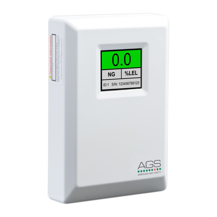
Page 15: Specification
Indoor, Safe Areas (not to be used in potentially explosive atmospheres) Green (Safe), Yellow (Special State) & Red (Alarm). Gas Type & Detected Concentration Level. Measured Indicators (1.8” TFT Screen) Value Detector ID No. Serial No. End of Life. Sensor Fault. Service. - Page 16 Every effort is made to ensure the accuracy of this document; however, CGS can assume no responsibility for any errors or omissions in this document or their consequences. CGS would greatly appreciate being informed of any errors or omissions that may be found in the content of this document.
Need help?
Do you have a question about the TFT and is the answer not in the manual?
Questions and answers