Table of Contents
Advertisement
Available languages
Available languages
Quick Links
BasementSentry.com
ATTACH YOUR RECEIPT HERE
Purchase Date
Questions, problems, missing parts? Before returning to your retailer, call our customer
service department at 1-800-742-5044, 7:30 a.m. - 5:00 p.m., EST, Monday - Friday.
BACKUP SUMP PUMP
1
© 2020. All rights reserved.
115V / 12V DC
COMBO SYSTEM
MODEL #STBC101
Español p. 13
SW1474 A
Advertisement
Table of Contents

Summary of Contents for Basement Sentry 115V
- Page 1 115V / 12V DC BACKUP SUMP PUMP COMBO SYSTEM MODEL #STBC101 Español p. 13 BasementSentry.com ATTACH YOUR RECEIPT HERE Purchase Date Questions, problems, missing parts? Before returning to your retailer, call our customer service department at 1-800-742-5044, 7:30 a.m. - 5:00 p.m., EST, Monday - Friday.
-
Page 2: Package Contents
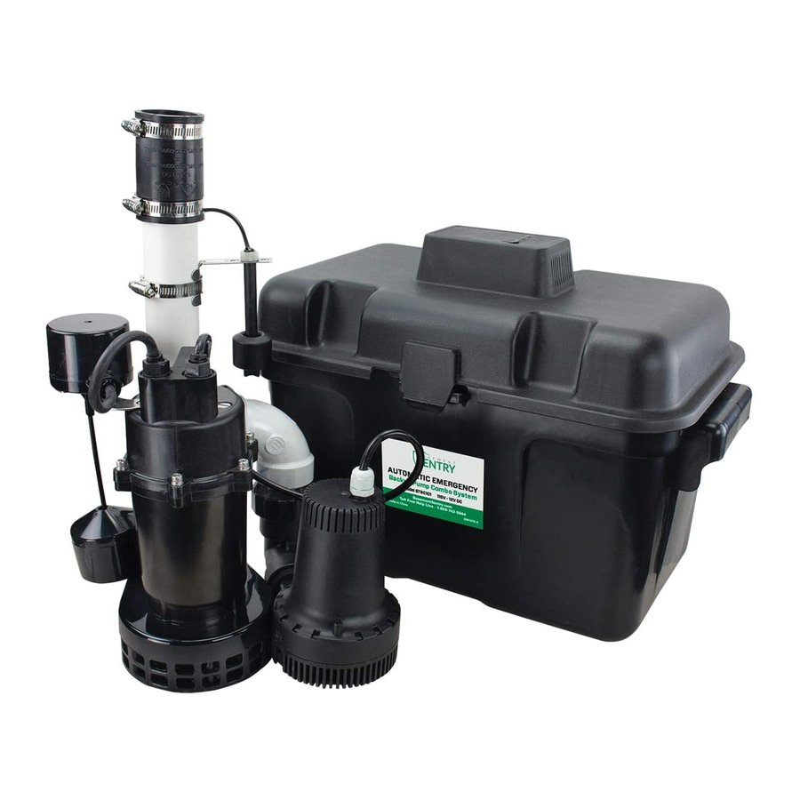
PACKAGE CONTENTS DESCRIPTION QUANTITY Primary/backup pump and pipe assembly (Includes: AC pump, DC pump, elbows, tee, check valves, DC float, discharge pipe and flex coupling/clamps) Battery box with built-in controller AC wall adapter SAFETY INFORMATION Please read and understand this entire manual before attempting to assemble, operate, or install the product. - Page 3 WARNING • ELECTRICAL SHOCK ALERT. Do not disassemble the motor housing. The motor has NO repairable internal parts and disassembly may cause dangerous electrical wiring issues. • ELECTRICAL SHOCK ALERT. Before installing this product, have the electrical circuit checked by an electrician to ensure proper grounding.
-
Page 4: General Pump Information
It is designed to work only during power outages or if the primary pump does not work. Because the system is pre-assembled, installation is quick and easy. The system includes a 115V pump, 12V pump, controller, alarm system, battery charger, float switch and battery box. -
Page 5: Installation Instructions
INSTALLATION INSTRUCTIONS NOTE: Install the battery backup system when the primary pump is not needed. Read instructions and prepare all supplies before beginning installation. 1. Manually operate the existing sump pump to remove as much water as possible from the basin. - Page 6 INSTALLATION INSTRUCTIONS 4. Place the 115V / 12VDC pump assembly in the sump basin. 5. Measure the distance between the household discharge pipe and the top of the115V / 12V DC pump assembly. Cut Sched 40 PVC pipe to fit this measurement.
- Page 7 Plug the float switch wire into the port marked ‘FLOAT’. c. Plug the 12V charger into the port marked ‘ADAPTER’. Plug the charger into a 115V GFCI protected power source. Once the charger is plugged in, the LED lights on the battery box should turn on.
- Page 8 INSTALLATION INSTRUCTIONS 10. Test all system connections by pressing the ‘RESET’ button for 1 - 4 seconds. The alarm will sound. This will cause the system to run a self- test and the DC pump will run for 3 seconds. To silence an alarm, press the ‘RESET’...
-
Page 9: Operation
NOTE: Sump basin must be filled with water before operation. Running the pump dry will cause damage and void the warranty. 1. Verify 115V pump operation by filling the basin with enough water to raise the float on the Lift primary sump pump. -
Page 10: Care And Maintenance
CARE AND MAINTENANCE WARNING: Always disconnect pump from power source before handling. Once a month: Press the reset button for 1-3 seconds to run a Clean out self-test. vent hole Remove At least every three months: debris • Remove any debris that may build up in the sump basin to prevent it from interfering with the operation of the float switch. -
Page 11: Troubleshooting
TROUBLESHOOTING DANGER RISK OF ELECTRIC SHOCK. Always disconnect power source before attempting to install, service, or maintain the pump. Never handle a pump with wet hands or when standing on wet or damp surface or in water. Fatal electrical shock could occur. PROBLEM POSSIBLE CAUSE CORRECTIVE ACTION... -
Page 12: Repair Parts
REPAIR PARTS ITEM DESCRIPTION 025400 12V DC Pump Battery Box w/ 025404 controller 025402 Float Switch 025403 AC Adapter 025401 90º Elbow © 2020. All rights reserved. - Page 13 115V / 12V CD BACKUP SISTEMA COMBINADO CON BOMBA DE SUMIDERO DE RESERVA MODELO #STBC101 BasementSentry.com ADJUNTE SU RECIBO AQUÍ Número de serie Fecha de compra ¿Preguntas, problemas, partes faltantes? Antes de acudir al minorista, llame a nuestro departamento de servicio al cliente al 1-800-742-5044, de lunes a viernes de 7:30 a.m.
-
Page 14: Contenido Del Paquete
CONTENIDO DEL PAQUETE DESCRIPCIÓN CANTIDAD Conjunto de bomba principal/ reserva y tubería (Incluye: Bomba de CA, bomba de CC, codos, T, válvulas de retención, flotador de CC, tubo de descarga y acoples/abrazaderas flexibles) Caja de batería con controlador incorporado Adaptador de pared de CA INFORMACIÓN DE SEGURIDAD Lea y comprenda todo el manual antes de intentar ensamblar, operar o instalar el producto. - Page 15 • ALERTA DE DESCARGA ELÉCTRICA Antes de instalar este producto, haga que un electricista revise su circuito para asegurarse de que la puesta a tierra sea adecuada. Todas las instalaciones eléctricas deben cumplir con el Código Nacional de Electricidad (NEC, por sus siglas en inglés) y con todos los códigos locales. •...
- Page 16 Este sistema de respaldo requiere una batería de 12 V de buena calidad para proporcionar el máximo tiempo de bombeo cuando sea necesario. Se recomienda un cargador de marca Basement Sentry. De lo contrario, use una batería marina AGM de ciclo profundo de 12 voltios y 105 amp-hora o más grande. Las baterías húmedas contienen ácido y hay que tener precaución al manipularlas.
-
Page 17: Instrucciones De Instalación
INSTRUCCIONES DE INSTALACIÓN NOTA: instale el sistema de respaldo de batería cuando no se necesite la bomba principal. Lea las instrucciones y prepare todos los materiales antes de comenzar la instalación. 1. Opere manualmente la bomba de sumidero principal para retirar la mayor cantidad posible de agua del contenedor para agua. - Page 18 INSTRUCCIONES DE INSTALACIÓN 4. Coloque el conjunto de la bomba de 115V / 12VDC en el contenedor para agua de sumidero. 5. Mida la distancia entre la tubería de descarga doméstica y la parte superior del conjunto de la bomba de 115V / 12V DC. Corte la tubería de PVC Schedule 40 para adaptarse a esta medida.
- Page 19 INSTRUCCIONES DE INSTALACIÓN 7. Coloque una batería marina de ciclo profundo completamente cargada en el interior de la caja de la batería. Conecte los cables de la caja de la batería desde el controlador hasta la batería: Rojo (+) a Rojo de la batería (+) Negro (-) a Negro de la batería (-) NOTA: la alarma sonará...
- Page 20 INSTRUCCIONES DE INSTALACIÓN 10. Compruebe todas las conexiones del sistema presionando el botón “RESET” (restablecer) durante 1 a 4 segundos. Sonará la alarma. Esto provocará que el sistema realice una autocomprobación y la bomba de CC funcionará durante 3 segundos. Red light on and alarm sounds: Para terminar la prueba, presione el botón “RESET”, Battery backup pump working...
- Page 21 OPERATION NOTA: el contenedor para agua de sumidero debe llenarse con agua antes del funcionamiento. Operar la bomba en seco provocará daños y anulará la garantía. 1. Verifique el funcionamiento de la bomba de 115 V Levante llenando el contenedor con suficiente agua para levantar el flotador de la bomba de sumidero flotador principal.
-
Page 22: Cuidado Y Mantenimiento
CUIDADO Y MANTENIMIENTO ADVERTENCIA: desconecte siempre la bomba de su fuente de alimentación antes de manipularla. Una vez al mez: Presione el botón de reinicio por 1-3 segundos para Limpie el orificio ejecutar un autotest de ventilación Al menos cada tres meses: Elimine los desechos •... -
Page 23: Solución De Problemas
SOLUCIÓN DE PROBLEMAS PELIGRO RIESGO DE CHOQUE ELÉCTRICO. Desconecte siempre la fuente de alimentación antes de intentar instalar, reparar o realizarle mantenimiento a la bomba. Nunca manipule una bomba con las manos mojadas ni cuando esté parado sobre una superficie húmeda o en el agua. -
Page 24: Piezas De Repuesto
PIEZAS DE REPUESTO Artículo Pieza No. Descripción 025400 Bomba de 12V DC Caja de batería con 025404 controlador Interruptor de 025402 flotador 025403 Adaptador de CA 025401 Codo de 90º © 2020. Todos los derechos reservados.
Need help?
Do you have a question about the 115V and is the answer not in the manual?
Questions and answers
I have a Sentry Sump Pump Combo Model STBC101 that has the alarm go off briefly with the red light flashing. It stops going off after awhile and the yellow light and green light come on and it says recharging. The red light and alarm come on briefly and then a solid green light. Circuit breaker is on the whole time.
@Mike Halaiko
When the alarm goes off briefly with a red light flashing on the Basement Sentry Sump Pump Combo Model STBC101, it means there is a pump wire connection problem or the pump has failed.
This answer is automatically generated