Table of Contents
Advertisement
Quick Links
Advertisement
Table of Contents

Related Manuals for Element 14 BeagleBone Black INDUSTRIAL

Summary of Contents for Element 14 BeagleBone Black INDUSTRIAL
- Page 1 element14 BeagleBone Black INDUSTRIAL System Reference Manual January 2016...
- Page 2 Systems Reference Manual which is provided care of CircuitCo with acknowledements to Gerald Coley of BeagleBoard.org. This reference manual includes detailed documentation for the element14 BeagleBone Black Industrial board, its use and its design. It serves as the primary resource for reference and technical support.
- Page 3 BEAGLEBONE DESIGN These design materials referred to in this document are *NOT SUPPORTED* and DO NOT constitute a reference design. Only “community” support is allowed via resources at BeagleBoard.org/discuss. THERE IS NO WARRANTY FOR THE DESIGN MATERIALS, TO THE EXTENT PERMITTED BY APPLICABLE LAW.
- Page 4 Should the element14 BeagleBone Black Industrial not meet the specifications indicated in the System Reference Manual, the element14 BeagleBone Black Industrial may be returned to the distributor of purchase for a full refund according to the terms and conditions offered by them.
- Page 5 BeagleBone should fail to perform as described or expected. Certain Instructions. It is important to operate the e l e m e n t 1 4 BeagleBone Black Industrial within Supplier’s recommended specifications and environmental considerations per the user guidelines. Exceeding the specified BeagleBone ratings (including but not limited to input and output voltage, current, power, and environmental ranges) may cause property damage, personal injury or death.
- Page 6 Before returning the board, please visit BeagleBoard.org/support For up to date SW images and technical information refer to http://elinux.org/Beagleboard:BeagleBoneBlack All support for this board is provided via community support at www.beagleboard.org/discuss element14 is a trademark of Premier Farnell plc © 2016 Premier Farnell plc. All Rights Reserved...
-
Page 7: Table Of Contents
Standalone w/Display and Keyboard/Mouse ....................17 14 B ..................23 ELEMENT EAGLE LACK NDUSTRIAL VERVIEW BeagleBone Compatibility ..........................24 element14 BeagleBone Black Industrial Features and Specification............. 25 Board Component Locations.......................... 26 14 B ............28 ELEMENT EAGLE LACK NDUSTRIAL EVEL PECIFICATION Block Diagram ............................... - Page 8 6.1.9 Power Rails ..............................42 6.1.10 Power LED ..............................46 6.1.11 TPS65217C Power Up Process ........................ 46 6.1.12 Processor Control Interface ........................47 6.1.13 Low Power Mode Support ........................47 6.2 S AM3358BZCZA100 P ....................... 48 ITARA ROCESSOR 6.2.1 Description..............................48 6.2.2 High Level Features ............................
- Page 9 Ethernet ................................88 JTAG Connector ............................. 88 8.0 C ............................89 OARD UPPORT element14 BeagleBone Black Industrial Cape Compatibility ................ 90 EEPROM ............................... 92 Pin Usage Consideration ..........................99 Expansion Connectors ..........................100 Signal Usage ..............................104 Cape Power..............................106 Mechanical..............................
- Page 10 CONNECTORS, LEDS AND SWITCHES ............. 26 FIGURE 18 KEY COMPONENTS ..................... 27 FIGURE 19 ELEMENT14 BEAGLEBONE BLACK INDUSTRIAL KEY COMPONENTS ..28 FIGURE 20 ELEMENT14 BEAGLEBONE BLACK INDUSTRIAL BLOCK DIAGRAM ....34 FIGURE 21 HIGH LEVEL POWER BLOCK DIAGRAM ............35 FIGURE 22 TPS65217C BLOCK DIAGRAM ................
- Page 11 SERIAL NUMBER FORMAT ................116 TABLES TABLE 1 ELEMENT14 BEAGLEBONE BLACK INDUSTRIAL FEATURES ......25 TABLE 2 ELEMENT14 BEAGLEBONE BLACK INDUSTRIAL BATTERY PINS ....40 TABLE 3 ELEMENT14 BEAGLEBONE BLACK INDUSTRIAL POWER CONSUMPTION (MA@5V) TABLE 4 PROCESSOR FEATURES ..................49 TABLE 5 EMMC BOOT PINS ....................
-
Page 12: Introduction
Board Changes 2.1.1 Rev A (Part#: BBONE-BLACK-IND-4G) • The BeagleBone Black Industrial board is based on the BeagleBone Black Rev C design and board configuration. For details on change history, board changes and revisions, please refer to the wiki http://elinux.org/Beagleboard:BeagleBoneBlack... -
Page 13: What's In The Box
2) As a standalone development platform in a desktop PC configuration. What’s In the Box In the box you will find three main items as shown in Figure 1. • element14 BeagleBone Black Industrial • miniUSB to USB Type A Cable • Quick Start Guide. -
Page 14: Tethered To A Pc
• Tethered to a PC via the USB cable o Board is accessed as a storage drive o Or a RNDIS Ethernet connection. • Standalone desktop o Display o Keyboard and mouse o External 5V power supply Each of these configurations is discussed in general terms in the following sections. For an up-to-date list of confirmed working accessories please go to http://elinux.org/Beagleboard:BeagleBone_Black_Accessories Tethered To A PC... -
Page 15: Figure 3 Usb Connection To The Board
Figure 3 USB Connection to the Board 2. Connect the large connec ector of the USB cable to your PC or laptop USB laptop USB port. 3. The board will power on a and the power LED will be on as shown in F Figure 4 below. -
Page 16: Figure 5 Board Boot Status
a few seconds for the status LEDs to come on, so be patient. The LEDs will be flashing in an erratic manner as it begins to boot the Linux kernel. Figure 5 Board Boot Status 3.3.2 Accessing the Board as a Storage Drive The board will appear around a USB Storage drive on your PC after the kernel has booted, which will take a round 10 seconds. -
Page 17: Standalone W/Display And Keyboard/Mouse
Standalone w/Display lay and Keyboard/Mouse In this configuration, the board wo works more like a PC, totally free from any connection to a PC as shown in Figure 6. It allows you to create your code to make e the board do whatever you need it to do. -
Page 18: Figure 7 Connect Microhdmi Cable To The Monitor
For an up-to-date list of confirmed working accessories please go to http://elinux.org/Beagleboard:BeagleBone_Black_Accessories Connecting Up the Board 3.4.2 1. Connect the big end of the HDMI cable as shown in Figure 7 to your HDMI monitor. Refer to your monitor Owner’s Manual for the location of your HDMI port. If you have a DVI-D Monitor go to Step 3, otherwise proceed to Step 4. -
Page 19: Figure 10 Connect Keyboard And Mouse Receiver To The Board
Figure 10 Connect Keyboard and Mouse Receiver to the Board Connect Keyboard and Mouse Receiver to the Board If you have a wired USB keyboard requiring two USB ports, you will need a HUB similar to If you have a wired USB keyboard requiring two USB ports, you will need a HUB similar to If you have a wired USB keyboard requiring two USB ports, you will need a HUB similar to the ones shown in Figure 11. -
Page 20: Figure 12 Ethernet Cable Connection
Figure Figure 12 Ethernet Cable Connection Apply Power The final step is to plug in the DC power supply to the DC power jack as shown in Figure The final step is to plug in the DC power supply to the DC power jack as shown in The final step is to plug in the DC power supply to the DC power jack as shown in 13 below. -
Page 21: Figure 14 Connect Microhdmi Cable To The Board
Figure 14 Connect microHDMI Cable to the Board The connector is fairly robust, but we suggest that you not use the cable as a leash for your Beagle. Take proper care not to put too much stress on the connector or cable. 6. -
Page 22: Figure 16 Desktop Screen
While the four user LEDS can be over written and used as desired, they do have specific meanings in the image that is shipped with the board once the Linux kernel has booted. • USER0 is the heartbeat indicator from the Linux kernel. •... -
Page 23: Element14 Beaglebone Black Industrial Overview
BeagleBone Black Industrial via onboard support of some interfaces. It is not a complete product designed to do any particular function. It is a foundation for experimentation and learning how to program the processor and to access the peripherals by the creation of your own software and hardware. -
Page 24: Beaglebone Compatibility
BeagleBone Compatibility The board is intended to be compatible with the original BeagleBone as much as possible. There are several areas where there are differences between the two designs. These differences are listed below, along with the reasons for the differences. •... -
Page 25: Element14 Beaglebone Black Industrial Features And Specification
While this disables audio to the HDMI, the fact that you want to use this pin for something else, does the same thing. element14 BeagleBone Black Industrial Features and Specification This section covers the specifications and features of the board and provides a high level description of the major components and interfaces that make up the board. -
Page 26: Board Component Locations
Board Component Locations This section describes the key components on the board. It provides information on their location and function. Familiarize yourself with the various components on the board. 4.3.1 Connectors, LEDs, and Switches Figure 17 below shows the locations of the connectors, LEDs, and switches on the PCB layout of the board. -
Page 27: Figure 18 Key Components
• USB Host can be connected different USB interfaces such as Wi-Fi, BT, Keyboard, etc. 4.3.2 Key Components Figure 18 below shows the locations of the key components on the PCB layout of the board. Figure 18 Key Components • Sitara AM3358BZCZD100 is the processor for the board. •... -
Page 28: Element 14 Beagle Bone Black Industrial High Level Specification
BeagleBone Black Industrial element14 BeagleBone Black Industrial High Level Spe ecification This section provides the high lev h level specification of the element14 BeagleBone one Black Industrial. Block Diagram Figure 19 below is the high leve el block diagram of the element14 BeagleBone one Black Industrial. -
Page 29: Memory
Memory Described in the following sections are the three memory devices found on the board. 5.3.1 512MB DDR3L A single 256Mb x16 DDR3L 4Gb (512MB) memory device is used. The memory used is one of two devices: MT41K256M16HA-125 from Micron D2516EC4BXGGB from Kingston It will operate at a clock frequency of 400MHz yielding an effective rate of 800MHZ on the DDR3L bus allowing for 1.6GB/S of DDR3L memory bandwidth. -
Page 30: Power Management
5.3.5 Boot Modes As mentioned earlier, there are four boot modes: • eMMC Boot…This is the default boot mode and will allow for the fastest boot time and will enable the board to boot out of the box using the pre-flashed OS image without having to purchase an microSD card or an microSD card writer. -
Page 31: Pc Usb Interface
DDR3L requires 1.5V instead of 1.8V on the DDR2 as is the case on the original BeagleBone. The 1.8V regulator setting has been changed to 1.5V for the DDR3L. The LDO3 3.3V rail has been changed to 1.8V to support those rails on the processor. LDO4 is still 3.3V for the 3.3V rails on the processor. -
Page 32: Reset Button
When pressed and released, causes a reset of the board. The reset button used on the element14 BeagleBone Black Industrial Industrial is a little larger than the one used on the original BeagleBone. It has also been moved out to the edge of the board so that it is more accessible. -
Page 33: Cti Jtag Header
• 1280 x 720 5.14 Cape Board Support The element14 BeagleBone Black Industrial has the ability to accept up to four expansion boards or capes that can be stacked onto the expansion headers. The word cape comes from the shape of the board as it is fitted around the Ethernet connector on the main board. -
Page 34: Detailed Hardware Design
Figure 19 back on page 31. I It is placed here again for convenience so it is closer is closer to the topics to follow. Figure 20 element14 BeagleBone Black Industrial element14 BeagleBone Black Industrial Block Diagram... -
Page 35: Power Section
Power Section Figure 21 is the high level block diagram of the power section of the board. Figure 21 High Level Power Block Diagram This section describes the power section of the design and all the functions performed by the TPS65217C. - Page 36 can be forced into fixed frequency PWM using the I C interface. The step-down converters allow the use of small inductors and capacitors to achieve a small footprint solution size. LDO1 and LDO2 are intended to support system standby mode. In normal operation, they can support up to 100mA each.
-
Page 37: Dc Input
Figure 22 TPS65217C Block Diagram 6.1.2 DC Input Figure 23 below shows how the DC input is connected to the TPS65217C. element14 is a trademark of Premier Farnell plc © 2016 Premier Farnell plc. All Rights Reserved... -
Page 38: Usb Power
Figure 23 TPS65217 DC Connection A 5VDC supply can be used to provide power to the board. The power supply current depends on how many and what type of add-on boards are connected to the board. For typical use, a 5VDC supply rated at 1A should be sufficient. If heavier use of the expansion headers or USB host port is expected, then a higher current supply will be required. -
Page 39: Power Selection
expansion headers, so capes that require the 5V rail to supply the cape direct, bypassing the TPS65217C, will not have that rail available for use. The 5VDC supply from the USB port is provided on the SYS_5V, the one that comes from the TPS65217C, rail of the expansion header for use by a cape. -
Page 40: Power Button
The pads can be loaded with a 4x4 header or you may just wire a battery into the pads. In addition they could provide access via a cape if desired. The four signals are listed below in Table 2. Table 2 element14 BeagleBone Black Industrial Battery Pins DESIGNATION FUNCTION Battery connection point. -
Page 41: Power Consumption
• Ethernet connected @ 100M • Serial debug cable connected Table 3 is an analysis of the power consumption of the board in these various scenarios. Table 3 element14 BeagleBone Black Industrial Power Consumption (mA@5V) MODE DC+USB Reset Idling @ UBoot... -
Page 42: Power Rails
6.1.8.3 LDO_GOOD This signal connects to the RTC_PORZn signal, RTC power on reset. The small n indicates that the signal is an active low signal. Word processors seem to be unable to put a bar over a word so the n is commonly used in electronics. As the RTC circuitry comes up first, this signal indicates that the LDOs, the 1.8V VRTC rail, is up and stable. -
Page 43: Figure 25 Power Rails
Figure 25 Power Rails 6.1.9.1 VRTC Rail The VRTC rail is a 1.8V rail that is the first rail to come up in the power sequencing. It provides power to the RTC domain on the processor and the I/O rail of the TPS65217C. It can deliver up to 250mA maximum. - Page 44 The current supplied by the VDD_3V3A rail is not sufficient to power all of the 3.3V rails on the board. So a second LDO is supplied, U4, a TL5209A, which sources the VDD_3V3B rail. It is powered up just after the VDD_3V3A rail. 6.1.9.4 VDD_1V8 Rail The VDD_1V8 rail can deliver up to 400mA and provides the power required for the...
-
Page 45: Figure 26 Power Rail Power Up Sequencing
Figure 26 Power Rail Power Up Sequencing Figure 27 the voltage rail sequencing for the TPS65217C as it powers up and the voltages on each rail. The power sequencing starts at 15 and then goes to one. That is the way the TPS65217C is configured. -
Page 46: Power Led
6.1.10 Power LED The power LED is a blue LED that will turn on once the TPS65217C has finished the power up procedure. If you ever see the LED flash once, that means that the TPS65217C started the process and encountered an issue that caused it to shut down. The connection of the LED is shown in Figure 25. -
Page 47: Processor Control Interface
6.1.12 Processor Control Interface Figure 28 above shows two interfaces between the processor and the TPS65217C used for control after the power up sequence has completed. The first is the I2C0 bus. This allows the processor to turn on and off rails and to set the voltage levels of each regulator to supports such things as voltage scaling. -
Page 48: Sitara Am3358Bzcza100 Processor
6.1.13.3 Voltage Scaling For a mode where the lowest power is possible without going to sleep, this mode allows the voltage on the ARM processor to be lowered along with slowing the processor frequency down. The I2C0 bus is used to control the voltage scaling function in the TPS65217C. -
Page 49: High Level Features
6.2.2 High Level Features Table 4 below shows a few of the high level features of the Sitara processor. Table 4 Processor Features Linux, Android, Windows Operating Systems MMC/SD mbedded CE,QNX, ThreadX 7 mW Standby Power ARM CPU 1 ARM Cortex-A8 UART (SCI) ARM MHz (Max.) 275,500,600,800,1000... -
Page 50: Crystal Circuitry
6.2.4 Crystal Circuitry Figure 30 is the crystal circuitry for the AM3358B processor. Figure 30 Processor Crystals 6.2.5 Reset Circuitry Figure 31 is the board reset circuitry. The initial power on reset is generated by the TPS65217C power management IC. It also handles the reset for the Real Time Clock. The board reset is the SYS_RESETn signal. -
Page 51: Memory Device
Board Reset Circuitry DDR3L Memory The element14 BeagleBone Black Industrial uses a single MT41K256M16HA-125 512MB DDR3L device from Micron that interfaces to the processor over 16 data lines, 16 address lines, and 14 control lines. The following sections provide more details on the design. -
Page 52: Ddr3L Memory Design
6.2.7 DDR3L Memory Design Figure 32 is the schematic for the DDR3L memory device. Each of the groups of signals is described in the following lines. Address Lines: Provide the row address for ACTIVATE commands, and the column address and auto pre-charge bit (A10) for READ/WRITE commands, to select one location out of the memory array in the respective bank. -
Page 53: Figure 32 Ddr3L Memory Design
Figure 32 DDR3L Memory Design Chip Select Line: CS# enables (registered LOW) and disables (registered HIGH) the command decoder. All commands are masked when CS# is registered HIGH. CS# provides for external rank selection on systems with multiple ranks. CS# is considered part of the command code. -
Page 54: Power Rails
6.2.8 Power Rails The DDR3L memory device and the DDR3 rails on the processor are supplied by the TPS65217C. Default voltage is 1.5V but can be scaled down to 1.35V if desired. 6.2.9 VREF The VREF signal is generated from a voltage divider on the VDDS_DDR rail that powers the processor DDR rail and the DDR3L device itself. -
Page 55: 4Gb Emmc Memory
4GB eMMC Memory The eMMC is a communication and mass data storage device that includes a Multi- MediaCard (MMC) interface, a NAND Flash component, and a controller on an advanced 11-signal bus, which is compliant with the MMC system specification. The nonvolatile eMMC draws no power to maintain stored data, delivers high performance across a wide range of operating temperatures, and resists shock and vibration disruption. -
Page 56: Figure 34 Emmc Memory Design
Figure 34 eMMC Memory Design The pins used by the eMMC1 in the boot mode are listed below in Table 5. Table 5 eMMC Boot Pins For eMMC devices the ROM will only support raw mode. The ROM Code reads out raw sectors from image or the booting file within the file system and boots from it. -
Page 57: Board Id Eeprom
Board ID EEPROM The BeagleBone is equipped with a single 32Kbit(4KB) 24LC32AT-I/OT EEPROM to allow the SW to identify the board. Table 6 below defined the contents of the EERPOM. Table 6 EEPROM Contents Name Size Contents (bytes) Header 0xAA, 0x55, 0x33, EE Board Name Name for board in ASCII: A335BONE Version... -
Page 58: Micro Secure Digital
However, most microSD connectors still supply a CD function on the connectors. In the element14 BeagleBone Black Industrial design, this pin is connected to the MMC0_SDCD pin for use by the processor. You can also change the pin to GPIO0_6, which is able to wake up the processor from a sleep mode when an microSD card is inserted into the connector. -
Page 59: User Leds
User LEDs There are four user LEDs on the element14 BeagleBone Black. These are connected to GPIO pins on the processor. Figure 37 shows the interfaces for the user LEDs. Figure 37 User LEDs Resistors R71-R74 was changed to 4.75K on the revision A5B board. Table 7 shows the signals used to control the four LEDs from the processor. -
Page 60: Boot Configuration
Boot Configuration The design supports two groups of boot options on the board. The user can switch between these modes via the Boot button. The primary boot source is the onboard eMMC device. By holding the Boot button, the user can force the board to boot from the microSD slot. -
Page 61: Default Boot Options
LCD panels. If you choose to override these settings, it is strongly recommended that you gate these signals with the SYS_RESETn signal. This ensures that after coming out of reset these signals are removed from the expansion pins. Default Boot Options Based on the selected option found in Figure 39 below, each of the boot sequences for each of the two settings is shown. -
Page 62: Ethernet Processor Interface
6.9.1 Ethernet Processor Interface Figure 40 shows the connections between the processor and the PHY. The interface is in the MII mode of operation. Figure 40 Ethernet Processor Interface This is the same interface as is used on the BeagleBone. No changes were made in this design for the board. -
Page 63: Ethernet Connector Interface
6.9.2 Ethernet Connector Interface The off board side of the PHY connections are shown in Figure 41 below. Figure 41 Ethernet Connector Interface This is the same interface as is used on the BeagleBone. No changes were made in this design for the board. element14 is a trademark of Premier Farnell plc ©... -
Page 64: Ethernet Phy Power, Reset, And Clocks
6.9.3 Ethernet PHY Power, Reset, and Clocks Figure 42 shows the power, reset, and lock connections to the LAN8710A PHY. Each of these areas is discussed in more detail in the following sections. Figure 42 Ethernet. PHY, Power, Reset and Clocks 6.9.3.1 VDD_3V3B Rail The VDD_3V3B rail is the main power rail for the LAN8710A. -
Page 65: Lan8710A Mode Pins
6.9.3.3 PHY_VDDCR Rail The PHY_VDDCR rail originates inside the LAN8710A. Filter and bypass capacitors are used to filter the rail. Only circuitry inside the LAN8710A uses this rail. 6.9.3.4 SYS_RESET The reset of the LAN8710A is controlled via the SYS_RESETn signal, the main board reset line. -
Page 66: Hdmi Interface
6.10 HDMI Interface The element14 BeagleBone Black Industrial has an onboard HDMI framer that converts the LCD signals and audio signals to drive a HDMI monitor. The design uses an NXP TDA19988 HDMI Framer. The following sections provide more detail into the design of this interface. -
Page 67: Hdmi Framer
DVI 1.0 and can be connected to any DVI 1.0 or HDMI sink. The HDCP mode is not used in the design. The non-HDCP version of the device is used in the element14 BeagleBone Black Industrial design. This device provides additional embedded features like CEC (Consumer Electronic Control). -
Page 68: Hdmi Control Processor Interface
Figure 44 HDMI Framer Processor Interface 6.10.4 HDMI Control Processor Interface In order to use the TDA19988, the processor needs to setup the device. This is done via the I2C interface between the processor and the TDA19988. There are two signals on the TDA19988 that could be used to set the address of the TDA19988. -
Page 69: Audio Interface
6.10.6 Audio Interface There is an I2S audio interface between the processor and the TDA19988. Stereo audio can be transported over the HDMI interface to an audio equipped display. In order to create the required clock frequencies, and external 24.576MHz oscillator, Y4, is used. From this clock, the processor generates the required clock frequencies for the TDA19988. -
Page 70: Power Connections
6.10.7 Power Connections Figure 46 shows the power connections to the TDA19988 device. All voltage rails for the device are at 1.8V. A filter is provided to minimize any noise from the 1.8V rail getting back into the device. Figure 46 HDMI Power Connections All of the interfaces between the processor and the TDA19988 are 3.3V tolerant allowing for direct connection. -
Page 71: Figure 47 Connector Interface Circuitry
Figure 47 Connector Interface Circuitry The connector for the HDMI interface is a microHDMI. It should be noted that this connector has a different pinout than the standard or mini HDMI connectors. D6 and D7 are ESD protection devices. element14 is a trademark of Premier Farnell plc ©... -
Page 72: Usb Host
6.11 USB Host The board is equipped with a single USB host interface accessible from a single USB Type A female connector. Figure 48 is the design of the USB Host circuitry. Figure 48 USB Host Circuitry 6.11.1 Power Switch U8 is a switch that allows the power to the connector to be turned on or off by the processor. -
Page 73: Pru-Icss
6.12 PRU-ICSS The PRU-ICSS module is located inside the AM3358 processor. Access to these pins is provided by the expansion headers and is multiplexed with other functions on the board. Access is not provided to all of the available pins. All documentation is located at http://github.com/beagleboard/am335x_pru_package. -
Page 74: Pru-Icss Pin Access
• UART0_TXD, UART0_RXD, UART0_CTS, UART0_RTS Table 10 below shows which PRU-ICSS signals can be accessed on the element14 BeagleBone Black Industrial and on which connector and pins they are accessible from. Some signals are accessible on the same pins. Table 10... -
Page 75: Connectors
Connectors This section describes each of the h of the connectors on the board. Expansion Connecto tors The expansion interface on the bo on the board is comprised of two 46 pin connectors. rs. All signals on the expansion headers are 3.3V 3.3V unless otherwise indicated. - Page 76 Table 11 shows the pinout of the P8 expansion header. Other signals can be connected to this connector based on setting the pin mux on the processor, but this is the default settings on power up. The SW is responsible for setting the default function of each pin. There are some signals that have not been listed here.
-
Page 77: Table 11 Expansion Header P8 Pinout
Table 11 Expansion Header P8 Pinout MODE4 MODE5 MODE6 MODE MODE MODE MODE2 MODE3 R9 GPIO1_6 gpmc_ad6 mmc1_dat6 gpio1[6] T9 GPIO1_7 gpmc_ad7 mmc1_dat7 gpio1[7] R8 GPIO1_2 gpmc_ad2 mmc1_dat2 gpio1[2] T8 GPIO1_3 gpmc_ad3 mmc1_dat3 gpio1[3] R7 TIMER4 gpmc_advn_a timer4 gpio2[2] T7 TIMER7 gpmc_oen_re timer7 gpio2[3]... - Page 78 7.1.2 Connector P9 Table 12 lists the signals on connector P9. Other signals can be connected to this connector based on setting the pin mux on the processor, but this is the default settings on power up. There are some signals that have not been listed here. Refer to the processor documentation for more information on these pins and detailed descriptions of all of the pins listed.
-
Page 79: Table 12 Expansion Header P9 Pinout
Table 12 Expansion Header P9 Pinout *GPIO3_21 is also the 24.576MHZ clock input to the processor to enable HDMI audio. To use this pin the oscillator must be disabled. element14 is a trademark of Premier Farnell plc © 2016 Premier Farnell plc. All Rights Reserved... -
Page 80: Power Jack
Power Jack The DC power jack is located next to the RJ45 Ethernet connector as shown in Figure 51. This uses the same power connector as is used on the original BeagleBone. The connector has a 2.1mm diameter center post (5VDC) and a 5.5mm diameter outer dimension on the barrel (GND). -
Page 81: Usb Client
USB Client The USB Client connector is ac ccessible on the bottom side of the board u under the row of four LEDs as shown in Figure 52 52. It uses a 5 pin miniUSB cable, the same me as is used on the original BeagleBone. -
Page 82: Usb Host
USB Host There is a single USB Host connector on the board and is shown in Figure 53 below. Figure 53 USB Host Connector The port is USB 2.0 HS compatible and can supply up to 500mA of current. If more current or ports is needed, then a HUB can be used. -
Page 83: Serial Header
Serial Header Each board has a debug serial interface that can be accessed by using a special serial cable that is plugged into the serial header as shown in Figure 54 below. Figure 54 Serial Debug Header Two signals are provided, TX and RX on this connector. The levels on these signals are 3.3V. -
Page 84: Figure 55 Ftdi Usb To Serial Adapter
Serial Debug Cable Pin 1 Figure 55 FTDI USB to Serial Adapter The cable can be purchased from several different places and must be the 3.3V version . Information on the cable itself can be found direct from FTDI at: TTL-232R-3V3 http://www.ftdichip.com/Support/Documents/DataSheets/Cables/DS_TTL- 232R_CABLES.pdf... - Page 85 PIN 1...
-
Page 86: Hdmi
HDMI Access to the HDMI interface is through the HDMI connector that is located on the bottom side of the board as shown in Figure 57 below. Figure 57 HDMI Connector The connector is microHDMI connector. This was done due to the space limitations we had in finding a place to fit the connector. -
Page 87: Microsd
microSD A microSD connector is located on the backside of the board as shown in Figure 59 below. The microSD card is not supplied with the board. microSD Connector Figure 59 microSD Connector When plugging in the SD card, the writing on the card should be up. Align the card with the connector and push to insert. -
Page 88: Ethernet
Ethernet The board comes with a single 10/100 Ethernet interface located next to the power jack as shown in Figure 60. 10/100 Ethernet Figure 60 Ethernet Connector The PHY supports AutoMDX which means either a straight or a swap cable can be used JTAG Connector A place for an optional 20 pin CTI JTAG header is provided on the board to facilitate the SW development and debugging of the board by using various JTAG emulators. -
Page 89: Cape Board Support
Cape Board Support The element14 BeagleBone Black Industrial has the ability to accept up to four expansion boards or capes that can be stacked onto the expansion headers. The word cape comes from the shape of the board as it is fitted around the Ethernet connector on the main board. -
Page 90: Element14 Beaglebone Black Industrial Cape Compatibility
BeagleBone Black Industrial Cape Compatibility The main expansion headers are the same between the BeagleBone and element14 BeagleBone Black. While the pins are the same, some of these pins are now used on the element14 BeagleBone Black. The following sections discuss these pins. -
Page 91: Table 15 P8 Emmc Conflict Pins
SW using the I2C0 interface. 8.1.2 eMMC Pins The element14 BeagleBone Black Industrial uses 10 pins to connect to the processor that also connect to the P8 expansion connector. These signals are listed below in Table 15. The proper mode is MODE2. -
Page 92: Eeprom
On power up, the eMMC is NOT reset. If you hold the Boot button down, this will force a boot from the microSD. This is not convenient when a cape is plugged into the board. There are two solutions to this issue: 1. -
Page 93: Figure 61 Expansion Board Eeprom Without Write Protect
Figure 61 Expansion Board EEPROM Without Write Protect The addressing of this device requires two bytes for the address which is not used on smaller size EEPROMs, which only require only one byte. Other compatible devices may be used as well. Make sure the device you select supports 16 bit addressing. The part package used is at the discretion of the cape designer. -
Page 94: Figure 62 Expansion Board Eeprom Write Protect
The I2C signals require pullup resistors. Each board must have a 5.6K resistor on these signals. With four capes installed this will be an effective resistance of 1.4K if all capes were installed and all the resistors used were exactly 5.6K. As more capes are added the resistance is reduced to overcome capacitance added to the signals. - Page 95 Version Hardware version code for board in ASCII. Version format is up to the developer. i.e. 02.1…00A1..10A0 Manufacturer ASCII name of the manufacturer. Company or individual’s name. Part Number ASCII Characters for the part number. Up to maker of the board. Number of Pins Number of pins used by the daughter board including the power pins used.
- Page 96 Bit 4 PU/PD 0=Pulldown 1=Pullup. Bit 3 PULLUP/DN 0=Pullup/pulldown enabled 1= Pullup/pulldown disabled Bit 2-0 MUX MODE SELECT Mode 0-7. (refer to TRM) Refer to the TRM for proper settings of the pin MUX mode based on the signal selection to be used.
-
Page 97: Table 17 Eeprom Pin Usage
Table 17 EEPROM Pin Usage 15 14 13 12 11 10 9 8 7 6 5 4 3 Conn Name Type Reserved Mux Mode Usage P9-22 UART2_RX P9-21 UART2_TX P9-18 I2C1_SDA P9-17 I2C1_SCL P9-42 GPIO0_7 P8-35 UART4_CTS P8-33 UART4_RTS P8-31 UART5_CTS P8-32 UART5_RTS... - Page 98 15 14 13 12 11 10 9 8 7 6 5 4 3 Conn Name Type Reserved Mux Mode Usage P9-23 GPIO1_17 P9-14 EHRPWM1 P9-16 EHRPWM1 P9-12 GPIO1_28 P8-26 GPIO1_29 P8-21 GPIO1_30 P8-20 GPIO1_31 P8-18 GPIO2_1 P8-7 TIMER4 P8-9 TIMER5 P8-10 TIMER6 P8-8...
-
Page 99: Pin Usage Consideration
15 14 13 12 11 10 9 8 7 6 5 4 3 Conn Name Type Reserved Mux Mode Usage 0 0 0 0 0 0 0 P9-39 AIN0 P9-40 AIN1 P9-37 AIN2 P9-38 AIN3 P9-33 AIN4 P9-36 AIN5 P9-35 AIN6 Pin Usage Consideration This section covers things to watch for when hooking up to certain pins on the expansion... -
Page 100: Expansion Connectors
If you plan to use any of these signals, then on power up, these pins should not be driven. If you do, it can affect the boot mode of the processor and could keep the processor from booting or working correctly. If you are designing a cape that is intended to be used as a boot source, such as a NAND board, then you should drive the pins to reconfigure the boot mode, but only at reset. -
Page 101: Figure 65 Single Cape Expansion Connector
It should be noted, that the longer the pin and the further it is inserted into the element14 BeagleBone Black Industrial connector, the harder it will be to remove due to the tension on 92 pins. This can be minimized by using shorter pins or removing those pins that are not used by your particular design. -
Page 102: Figure 66 Expansion Connector
It should be noted, that the longer the pin and the further it is inserted into the element14 BeagleBone Black Industrial connector, the harder it will be to remove due to the tension on 92 pins. This can be minimized by using shorter pins. There are most likely other suppliers out there that will work for this connector as well. -
Page 103: Figure 68 Stacked W/Signal Stealing Expansion Connector
This section will attempt to describe the tradeoffs and things to consider when selecting a connector and its pin length. 8.4.5 element14 BeagleBone Black Industrial Female Connectors Figure 69 shows the key measurements used in calculating how much the pin extends past the contact point on the connector, what we call overhang. -
Page 104: Signal Usage
Figure 69 Connector Pin Insertion Depth To calculate the amount of the pin that extends past the Point of Contact, use the following formula: Overhang=Total Pin Length- PCB thickness (.062) - contact point (.079) The longer the pin extends past the contact point, the more force it will take to insert and remove the board. - Page 105 DO NOT APPLY VOLTAGE TO ANY I/O PIN WHEN POWER IS NOT SUPPLIED TO THE BOARD. IT WILL DAMAGE THE PROCESSOR AND VOID THE WARRANTY. NO PINS ARE TO BE DRIVEN UNTIL AFTER THE SYS_RESET LINE GOES HIGH. element14 is a trademark of Premier Farnell plc ©...
-
Page 106: Cape Power
SYS_5V 250mA The VDD_3V3B rail is supplied by the LDO on the element14 BeagleBone Black Industrial and is the primary power rail for expansion boards. If the power requirement for the capes exceeds the current rating, then locally generated voltage rail can be used. It is recommended that this rail be used to power any buffers or level translators that may be used. -
Page 107: Mechanical
5) If you are applying signals from other boards into the expansion headers, make sure you power the board up after you power up the element14 BeagleBone Black Industrial or make the connections after power is applied on both boards. -
Page 108: Figure 70 Cape Board Dimensions
BeagleBone Black Industrial and why they are different. This is a result of having the BeagleBone fit into the Altoids style tin. It is not required that the cape be exactly like the element14 BeagleBone Black Industrial board in this respect. - Page 109 There are numerous enclosures being created in all different sizes and styles. The mechanical design of these enclosures is not being defined by this specification. The ability of these designs to handle all shapes and sizes of capes, especially when you consider up to four can be mounted with all sorts of interface connectors, it is difficult to define a standard enclosure that will handle all capes already made and those yet to be defined.
-
Page 110: Element14 Beaglebone Black Industrial Mechanical
BeagleBone Black Industrial Mechanical Dimensions and Weight Size : 3.5” x 2.15” (86.36mm x 53.34mm) Max height : .187” (4.76mm) PCB Layers PCB thickness : .062” RoHS Compliant : Yes Weight: 1.4 oz Silkscreen and Component Locations Figure 71... -
Page 111: Figure 72 Component Side Silkscreen
Figure 72 Component Side Silkscreen element14 is a trademark of Premier Farnell plc © 2016 Premier Farnell plc. All Rights Reserved... -
Page 112: Figure 73 Circuit Side Silkscreen
Figure 73 Circuit Side Silkscreen element14 is a trademark of Premier Farnell plc © 2016 Premier Farnell plc. All Rights Reserved... -
Page 113: Pictures
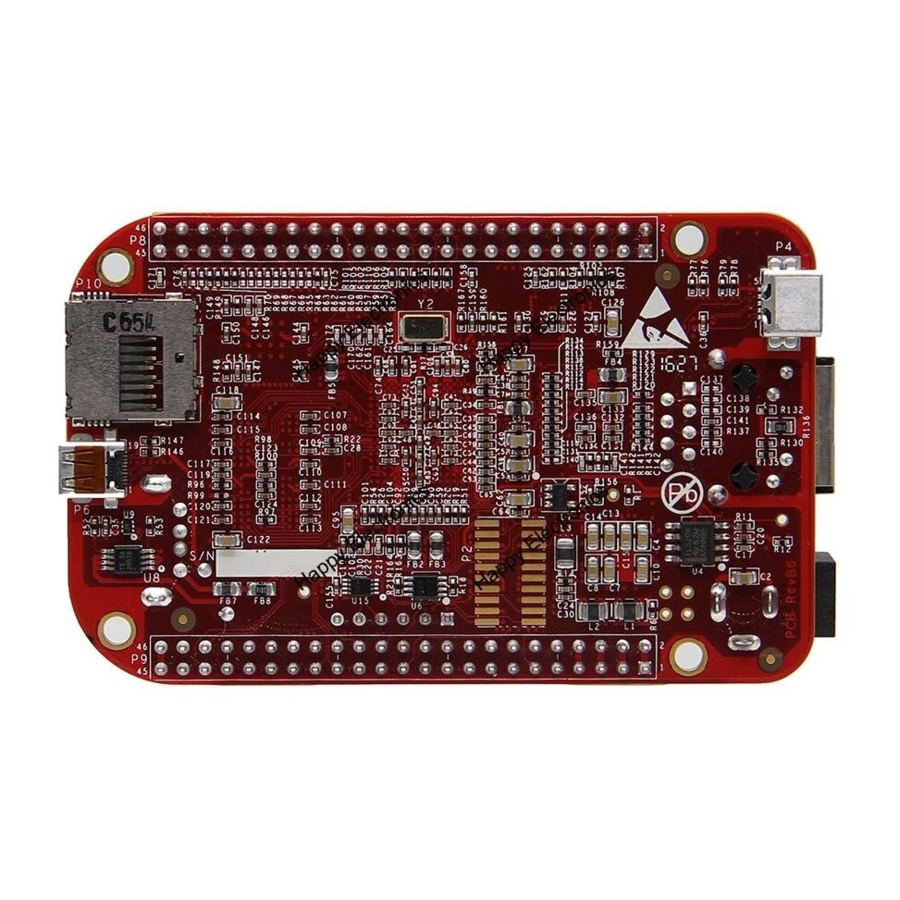
10.0 Pictures Figure 74 Top Side element14 is a trademark of Premier Farnell plc © 2016 Premier Farnell plc. All Rights Reserved... -
Page 114: Support Information
Figure 75 Bottom Side 11.0 Support Information All support for this design is through the BeagleBoard.org community at: beagleboard@googlegroups.com http://beagleboard.org/discuss 11.1 Hardware Design Design documentation can be found on the eMMC of the board under the documents/hardware directory when connected using the USB cable. Provided there is: •... -
Page 115: Software Updates
• Bill of Material • System Reference Manual (This document). This directory is not always kept updated in every SW release due to the frequency of changes of the SW. The best solution is to download the files from the WIKI at http://elinux.org/Beagleboard:BeagleBoneBlack We do not track SW revision of what is in the eMMC. -
Page 116: Rma Support
11.3 RMA Support If you feel your board is defective or has issues, please request an RMA from the channel you purchased the element14 BeagleBone Black Industrial. You will need the serial number and revision of the board. Figure 76... -
Page 117: Trouble Shooting Hdmi Issues
11.4 Trouble Shooting HDMI Issues Many people are having issues with getting HDMI to work on their TV/Display. Unfortunately, we do not have the resources to buy all the TVs and Monitors on the market today nor go to Ebay and buy all of the TVs and monitors made over the last five years to thoroughly test each and every one. - Page 118 11.4.3 OUT OF SEQUENCE Sometimes the display and the board can get confused. One way to prevent this is after everything is cabled up and running, you can power cycle the display, with the board still running. You can also try resetting the board and let it reboot to resync with the TV. 11.4.4 OVERSCAN Some displays use what is called overscan.
Need help?
Do you have a question about the BeagleBone Black INDUSTRIAL and is the answer not in the manual?
Questions and answers