Table of Contents
Advertisement
Available languages
Available languages
Quick Links
T E C H N O L O G Y F O R T H E W E L D E R ´ S W O R L D .
DE Betriebsanleitung / EN Operating instructions
FR Mode d´emploi / ES Instructivo de servicio
WH/VTS-Interlock/ABIROB W/ABIROB A/350GC/ABITIG-WH
Einstellvorrichtung
DE
EN
Alignment Jig
FR
Marbre de contrôle et de rectification
ES
Verificador / alineador de cuello
DIN EN
ISO 9001
www.binzel-abicor.com
Advertisement
Chapters
Table of Contents

Related Manuals for BINZEL-ABICOR WH-Interlock

Summary of Contents for BINZEL-ABICOR WH-Interlock
- Page 1 T E C H N O L O G Y F O R T H E W E L D E R ´ S W O R L D . DE Betriebsanleitung / EN Operating instructions FR Mode d´emploi / ES Instructivo de servicio WH/VTS-Interlock/ABIROB W/ABIROB A/350GC/ABITIG-WH Einstellvorrichtung Alignment Jig Marbre de contrôle et de rectification Verificador / alineador de cuello DIN EN ISO 9001 www.binzel-abicor.com...
-
Page 2: Table Of Contents
Produktes erforderlich werden. Diese Änderungen werden jedoch in neuen Ausgaben berücksichtigt. Alle in der Betriebsanleitung genannten Handelsmarken und Schutzmarken sind Eigentum der jeweiligen Besitzer/Hersteller. Unsere aktuellen Produktdokumente, sowie alle Kontaktdaten der ABICOR BINZEL Ländervertretungen und Partner weltweit, finden Sie auf unserer Homepage www.binzel-abicor.com Identifikation DE-3... -
Page 3: Identifikation
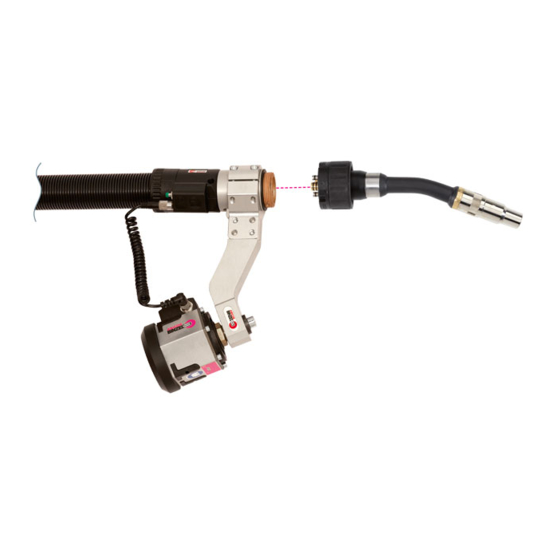
Einstellvorrichtung 1 Identifikation 1 Identifikation Mit der Einstellvorrichtung wird die Brennerhals - Ausrichtung (Biegewinkel) der wechselbaren Brennerhälse außerhalb der Schweißzelle überprüft. Weiterhin besteht auch die Möglichkeit, z. B. nach einer Kollision den Brennerhals bei gleicher Aufspannung geringfügig nachzurichten. Diese Betriebsanleitung beschreibt die Handhabung der Einstellvorrichtung. -
Page 4: Produktbeschreibung
3 Produktbeschreibung Einstellvorrichtung VORSICHT Bezeichnet eine möglicherweise schädliche Situation. Wenn sie nicht gemieden wird, können leichte oder geringfügige Verletzungen die Folge sein. HINWEIS Bezeichnet die Gefahr, dass Arbeitsergebnisse beeinträchtigt werden oder Sachschäden an der Ausrüstung die Folge sein können. 3 Produktbeschreibung WARNUNG Gefahren durch nicht bestimmungsgemäße Verwendung Bei nicht bestimmungsgemäßer Verwendung können vom Produkt Gefahren für Personen, Tiere und... -
Page 5: Verwendete Zeichen Und Symbole
Ausrüst- und Verschleißteile separat bestellen. Bestelldaten und Identnummern der Ausrüst- und Verschleißteile, entnehmen Sie den aktuellen Bestellunterlagen. Kontakt für Beratung und Bestellung finden Sie im Internet unter www.binzel-abicor.com. 4.1 Transport Der Lieferumfang wird vor dem Versand sorgfältig geprüft und verpackt, jedoch sind Beschädigungen während des Transportes nicht auszuschließen. -
Page 6: Einstellvorrichtung Aufstellen
5 Funktionsbeschreibung Einstellvorrichtung 5.1 Einstellvorrichtung aufstellen HINWEIS • Damit die Einstellvorrichtung verzugsfrei aufgeschraubt werden kann, muss der Aufstellungsort eine ebene Oberfläche haben, sollte trocken und frei von Verschmutzungen sein. Richthebel und Halterung Einspannkörper Führungskörper,kpl Brennerhals Grundplatte mit Prüfeinrichtung Abb. 1 Einstellvorrichtung aufstellen 1 Einstellvorrichtung befestigen. -
Page 7: Varianten
Einstellvorrichtung 5 Funktionsbeschreibung 5.1.1 Varianten ® Einspannkörper ABIROB 350GC Einspannkörper 13 Messhülse Einspannkörper ROBO VTS ABITIG-WH 220W/400W 14 Richthülse ® ® Einspannkörper ABIROB Spannbügel 15 Adapter für ABIROB ® Einspannkörper ABIROB Brennerhals 16 Brennerhals ROBO VTS ® Einspannkörper WH ABITIG-WH 220W/400W 17 Brennerhals ABIROB 350GC Rändelschraube... -
Page 8: Bedienung
6 Bedienung Einstellvorrichtung Die Richthülsen sind brennerspezifisch und unterscheiden sich in der Art der Befestigung: ® aufgesteckt WH 241/242, ROBO VTS 500, ABIROB 350 GC M23x1,5 WH 455 ® ROBO VTS 500 TS, ABIROB W 500 TS M22x2 ROBO VTS 290 ®... -
Page 9: Ausrichtung Überprüfen
Einstellvorrichtung 6 Bedienung 6.1.1 Ausrichtung überprüfen 1 Gasdüse abschrauben bzw. abziehen und weitere brennerspezifischen Ausrüstteile entfernen. Prüfdorn Messhülse Abb. 4 Ausrichtung prüfen 2 Messhülse (2) an Stelle der Stromdüse einschrauben. Der Biegewinkel ist in Ordnung, wenn der Prüfdorn (1) leichtgängig in die Bohrung der Messhülse (2) passt. 6.2 Biegewinkel justieren VORSICHT Sachschaden... -
Page 10: Wartung Und Reinigung
7 Wartung und Reinigung Einstellvorrichtung 7 Wartung und Reinigung Regelmäßige und dauerhafte Wartung und Reinigung sind Voraussetzung für eine lange Lebensdauer und eine einwandfreie Funktion. WARNUNG Quetschgefahr Einziehen und zerquetschen der Hände durch laufende Räder. • Nicht in laufende Räder greifen. 7.1 Monatlich Eine monatliche Grundreinigung ist empfehlenswert, bei extremen Arbeitsbedingungen notwendig. -
Page 11: Betriebsmittel
Einstellvorrichtung 10 Entsorgung 10.2 Betriebsmittel Öle, Schmierfette und Reinigungsmittel dürfen nicht den Boden belasten und in die Kanalisation gelangen. Diese Stoffe müssen in geeigneten Behältern aufbewahrt, transportiert und entsorgt werden. Beachten Sie dabei die entsprechenden örtlichen Bestimmungen und die Hinweise zur Entsorgung der vom Betriebsmittelhersteller vorgegebenen Sicherheitsdatenblätter. - Page 12 All brand names and trademarks that appear in these operating instructions are the property of their respective owners/ manufacturers. Our latest product documents as well as all contact details for the ABICOR BINZEL national subsidiaries and partners worldwide can be found on our website at www.binzel-abicor.com Identification EN-3...
-
Page 13: Identification
Alignment jig 1 Identification 1 Identification The alignment (bending angle) of the changeable torch necks outside of the welding cell can be checked using the alignment jig. Furthermore, it is also possible to realign the torch neck slightly with identical clamping, for example after a collision. -
Page 14: Classification Of The Warnings
3 Product description Alignment jig 2.4 Classification of the warnings The warnings used in the operating instructions are divided into four different levels and are shown prior to potentially dangerous work steps. Arranged in descending order of importance, they have the following meaning: DANGER Describes an imminent threatening danger. -
Page 15: Abbreviations
Order the equipment parts and wear parts separately. Order data and ID numbers for the equipment parts and wear parts can be found in the current catalogue. Contact details for advice and orders can be found online at www.binzel-abicor.com. 4.1 Transport Although the items delivered are carefully checked and packaged, it is not possible to exclude the risk of transport damage. -
Page 16: Storage
5 Functional Description Alignment jig Goods-in Use the delivery note to check that everything has been delivered. inspection Check the delivery for damage (visual inspection). In case of If the delivery has been damaged during transportation, contact the last carrier complaints immediately. - Page 17 Alignment jig 5 Functional Description Adjusting lever and holder Clamping body Guide device,cmpl Torch neck Base plate with test device Abb. 1 Installing the alignment jig 1 Fasten the alignment jig. 2 Mount (5) the clamping device and the guide device according to the bending angle to be checked (3) on the base plate (4).
-
Page 18: Versions
5 Functional Description Alignment jig 5.1.1 Versions ® Clamping device ABIROB 350GC Clamping device 13 Measuring sleeve Clamping device ROBO VTS ABITIG-WH 220W/400W 14 Adjusting sleeve ® ® Clamping device ABIROB Clamping bracket 15 Adapter for ABIROB ® Clamping device ABIROB Torch neck 16 Torch neck ROBO VTS ®... -
Page 19: Operation
Alignment jig 6 Operation The adjusting sleeves are torch-specific and are fastened differently: ® Plugged on WH 241/242, ROBO VTS 500, 350 GC ABIROB M23x1.5 WH 455 ® ROBO VTS 500 TS, W 500 TS ABIROB M22x2 ROBO VTS 290 ®... -
Page 20: Check The Alignment
6 Operation Alignment jig 6.1.1 Check the alignment. 1 Unscrew or pull out the gas nozzle and remove other torch-specific fittings. Test mandrel Measuring sleeve Abb. 4 Checking the Alignment 2 Screw in the measuring sleeve (2) at the position of the contact tip. The bending angle is correct if the test mandrel (1) fits easily into the bore of the measuring sleeve (2). -
Page 21: Maintenance And Cleaning
Alignment jig 7 Maintenance and cleaning 7 Maintenance and cleaning Scheduled maintenance and cleaning is a prerequisite for a long life and a trouble-free operation. WARNING Danger of crushing Parts of the body can be crushed between the torch neck and the guide device when aligning the torch neck during normal operation. -
Page 22: Disassembly
9 Disassembly Alignment jig 9 Disassembly NOTICE • Disassembly may only be carried out by qualified personnel (in Germany see TRBS 1203).. 10 Disposal When disposing of the system, local regulations, laws, provisions, standards and guidelines must be observed. Observe the regulations on the disposal of electronic scrap and dispose of it at your local waste disposal site (e.g. - Page 23 Alignment jig Notes Notes BAL.0022 • 2017-02-15 EN - 13...
- Page 24 Para obtener la documentación actual sobre nuestros productos así como para conocer los datos de contacto de los representantes locales y socios de ABICOR BINZEL en todo el mundo, consulte nuestra página de inicio en www.binzel-abicor.com Identificación ES-3 Operación...
-
Page 25: Identificación
Verificador/alineador de cuello 1 Identificación 1 Identificación El verificador/alineador de cuello puede utilizarse para comprobar la alineación (ángulo de flexión) de los cuellos de antorcha cambiables fuera de la célula de soldadura. Además es posible, por ejemplo después de una colisión, realinear el cuello de antorcha con la misma fijación en escasa medida. Este instructivo de servicio describe el manejo del verificador/alineador de cuello. -
Page 26: Descripción Del Producto
3 Descripción del producto Verificador/alineador de cuello ¡ATENCIÓN! Indica una situación posiblemente dañina. Si no se evita, las consecuencias pueden ser lesiones leves. AVISO Indica un riesgo de efectos negativos sobre los resultados de trabajo o de daños materiales en el equipo. -
Page 27: Signos Y Símbolos Utilizados
Solicite los accesorios y las piezas de repuesto por separado. Los datos de pedido y los números de identificación de accesorios y piezas de repuesto pueden consultarse en el catálogo más reciente. En nuestra página web www.binzel-abicor.com encontrará los datos de contacto para asesoramiento y pedidos. -
Page 28: Descripción Del Funcionamiento
5 Descripción del funcionamiento Verificador/alineador de cuello 5 Descripción del funcionamiento Fijar el cuello al comprobar el ángulo de flexión correspondiente en un dispositivo de fijación. Después de una colisión es posible reajustar el cuello de antorcha mediante la palanca de ajuste. ¡ADVERTENCIA! Riesgo de aplastamiento Pueden aplastarse partes del cuerpo entre el cuerpo de antorcha y el dispositivo de guía al alinear el... -
Page 29: Versiones
Verificador/alineador de cuello 5 Descripción del funcionamiento 5.1.1 Versiones Dispositivo de fijación Dispositivo de fijación 13 Casquillo de medición ® ABIROB 350GC ABITIG-WH 220W/400W 14 Casquillo de ajuste ® Dispositivo de fijación ROBO VTS Brazo de sujeción 15 Adaptador para ABIROB ®... -
Page 30: Operación
6 Operación Verificador/alineador de cuello Los casquillos de ajuste son específicos para cada antorcha y se fijan de forma diferente. ® encajados WH 241/242, ROBO VTS 500, ABIROB 350 GC M23x1,5 WH 455 ® ROBO VTS 500 TS, ABIROB W 500 TS M22x2 ROBO VTS 290 ®... -
Page 31: Controlar La Alineación
Verificador/alineador de cuello 6 Operación 6.1.1 Controlar la alineación 1 Destornillar la tobera de gas o retirarla y retirar otros accesorios específicos de la antorcha. Espiga de control Casquillo de medición Fig. 4 Controlar la alineación 2 Introducir el casquillo de medición (2) en la posición del tubo/punta de contacto. El ángulo de flexión es correcto si la espiga de control (1) entra fácilmente en el orificio del casquillo de medición (2). -
Page 32: Mantenimiento Y Limpieza
7 Mantenimiento y limpieza Verificador/alineador de cuello 7 Mantenimiento y limpieza El mantenimiento y la limpieza regulares son la condición previa para una larga vida útil y un funcionamiento perfecto. ¡ADVERTENCIA! Riesgo de aplastamiento Pueden aplastarse partes del cuerpo entre el cuerpo de antorcha y el dispositivo de guía al alinear el cuello durante el servicio normal. -
Page 33: Combustibles
Verificador/alineador de cuello 10 Eliminación 10.2 Combustibles Los aceites, los lubricantes y los detergentes no deben contaminar el suelo ni llegar al alcantarillado. Estas sustancias deben almacenarse, transportarse y eliminarse en tanques apropiados. Observe en esto las correspondientes disposiciones locales y las indicaciones para la eliminación de desechos dadas en las hojas de datos de seguridad que especifica el fabricante de medios de producción. - Page 34 Toutes les marques déposées et marques commerciales contenues dans le présent mode d'emploi sont la propriété de leurs titulaires/fabricants respectifs. Vous trouverez nos documents actuels sur les produits, ainsi que l'ensemble des coordonnées des représentants et des partenaires d'ABICOR BINZEL dans le monde sur la page d'accueil www.binzel-abicor.com. Identification FR-3...
-
Page 35: Identification
Le marbre de contrôle et de rectification 1 Identification 1 Identification Le marbre de contrôle et de rectification permet de contrôler l’orientation (angle de flexion) des cols de cygne interchangeables en dehors de la cellule de soudage. Par ailleurs, il est possible aussi d’ajuster légèrement l’orientation du col de cygne après une collision tout en gardant le même serrage. -
Page 36: Description Du Produit
3 Description du produit Le marbre de contrôle et de rectification AVERTISSEMENT Signale une situation potentiellement dangereuse. Si ce danger n'est pas évité, des blessures graves peuvent en résulter. ATTENTION Signale un risque potentiel. Si ce risque n'est pas évité, des blessures légères ou bénignes peuvent en résulter. -
Page 37: Plaque Signalétique
Les pièces d'équipement et d’usure sont à commander séparément. Les caractéristiques et références des pièces d’équipement et d’usure figurent dans le catalogue actuel. Pour obtenir des conseils et pour passer vos commandes, consultez le site www.binzel-abicor.com. Contrôle à la Contrôler à l'aide du bon de livraison si la livraison est complète ! réception... -
Page 38: Description Du Fonctionnement
5 Description du fonctionnement Le marbre de contrôle et de rectification 5 Description du fonctionnement Le col de cygne à vérifier est serré dans un corps de fixation, suivant l’angle de flexion. Un levier d’ajustage permet d’ajuster légèrement le col de cygne à la suite d’une collision. AVERTISSEMENT Risque d’écrasement Lors de l’orientation du col de cygne dans le mode de fonctionnement normal, des parties du corps se... -
Page 39: Versions
Le marbre de contrôle et de rectification 5 Description du fonctionnement 5.1.1 Versions Organe de serrage Organe de serrage 13 Douille de mesure ® ABIROB 350GC ABITIG-WH 220W/400W 14 Douille d’ajustage ® Organe de serrage ROBO VTS Etrier de blocage 15 Adaptateur, pour ABIROB ®... -
Page 40: Utilisation
6 Utilisation Le marbre de contrôle et de rectification Les douilles d'ajustage sont spécifiques aux torches et se distinguent par leur type de fixation : ® Fixation enfichable WH 241/242, ROBO VTS 500, ABIROB 350 GC M23x1,5 WH 455 ® ROBO VTS 500 TS, ABIROB W 500 TS M22x2... -
Page 41: Vérification De L'orientation
Le marbre de contrôle et de rectification 6 Utilisation 6.1.1 Vérification de l’orientation 1 Dévisser ou retirer la buse-gaz et enlever d’autres pièces d’usure spécifiques à la torche. Tige de contrôle Douille de mesure Fig. 4 Vérification de l’orientation 2 Visser la douille de mesure (2) à l’endroit du tube-contact. L'angle de flexion est correct lorsque la tige de contrôle (1) entre légèrement dans l’alésage de la douille de mesure (2). -
Page 42: Entretien Et Nettoyage
7 Entretien et nettoyage Le marbre de contrôle et de rectification 7 Entretien et nettoyage L'entretien et le nettoyage réguliers et permanents sont indispensables pour une longue durée de vie et un bon fonctionnement. AVERTISSEMENT Risque d'écrasement Risque d'écrasement des mains par l'engrenage en marche. •... -
Page 43: Produits Consommables
Le marbre de contrôle et de rectification 10 Elimination 10.2 Produits consommables Les huiles, graisses lubrifiantes et agents de nettoyage ne doivent pas polluer le sol et pénétrer dans les égouts. Ces matériaux doivent être conservés, transportés et éliminés dans des récipients appropriés. Respectez à... - Page 44 T E C H N O L O G Y F O R T H E W E L D E R ´ S W O R L D . Alexander Binzel Schweisstechnik GmbH & Co.KG Postfach 10 01 53 • D–35331 Giessen Tel.: ++49 (0) 64 08 / 59–0 Fax: ++49 (0) 64 08 / 59–191 Email: info@binzel-abicor.com www.binzel-abicor.com...
Need help?
Do you have a question about the WH-Interlock and is the answer not in the manual?
Questions and answers