
Related Manuals for DryGair DG-X


Summary of Contents for DryGair DG-X
- Page 1 DryGair Dehumidification Unit Model DG-X 360° Air Circulation Installation, Operation, and Maintenance Manual December 2020 Ver. 12/2020...
- Page 2 : drygair.energies Proprietary and Confidential Copyright © 2020 by DryGair Energies Ltd. All rights reserved. No part of this manual may be reproduced or copied in any form by any means- graphic, electronic, or mechanical, including photocopying, typing, or information retrieval systems- without written permission of DryGair Energies Ltd.
- Page 3 DryGair Dehumidification Unit Model DG-X Table of Contents TABLE OF CONTENTS Introduction _________________________________________ 1 Safety ______________________________________________ 3 Unit Overview ________________________________________ 5 Installation __________________________________________ 8 Ver. 12/2020...
- Page 4 Table of Contents Unit Parts and Components ___________________________ 20 Unit Operation ______________________________________ 26 Maintaining the Unit __________________________________ 34 DryGair Energies Ltd .
- Page 5 DryGair Dehumidification Unit Model DG-X Table of Contents Troubleshooting and Repairing the Unit _________________ 41 Appendices _________________________________________ 43 10. Comments and Notes ________________________________ 46 Ver. 12/2020...
-
Page 6: Table Of Contents
List of Figures LIST OF FIGURES Figure 3-1. DryGair unit (front and side view) ____________________________________ 6 Figure 3-2. DryGair Identification label __________________________________________ 7 Figure 4-1. Forklift addons __________________________________________________ 11 Figure 4-2. DG-X carton package ____________________________________________ 13 Figure 4-3. Rails as shipped _________________________________________________ 15 Figure 4-4. -
Page 7: Introduction
Introduction INTRODUCTION This manual provides instructions for installing and operating the DryGair unit Model DG-X correctly and safely and includes maintenance procedures and unit troubleshooting. Note: As DryGair continuously develops its machines to their maximum potential, this manual, though completely up to date when issued, is subject to changes without notice. - Page 8 Note Information given in a note describes how the part/unit functions or provides a tip on how best to use it. DryGair Energies Ltd .
-
Page 9: Safety
DryGair Dehumidification Unit Model DG-X Safety SAFETY DryGair Energies Ltd. believes that the safety of personnel working with and around the unit is the most important consideration. The DryGair unit is equipped with all the safety devices necessary to ensure risk-free use under standard conditions. - Page 10 • Secure electrical wires and cables to prevent damage. • The protecting doors and covers should not be opened during machine operation. • Replace all safety shields after completing set-up, troubleshooting, and maintenance procedures. DryGair Energies Ltd .
-
Page 11: Unit Overview
DryGair Dehumidification Unit Model DG-X Unit Overview UNIT OVERVIEW The DryGair DG-X unit is designed for indoor room dehumidification or small greenhouses. The unit reduces the humidity in the closed structure according to a defined set-point by pulling the wet cold air from the bottom of the room, extracting the water, and blowing the drier and warmer air back into the room through an air distribution module. -
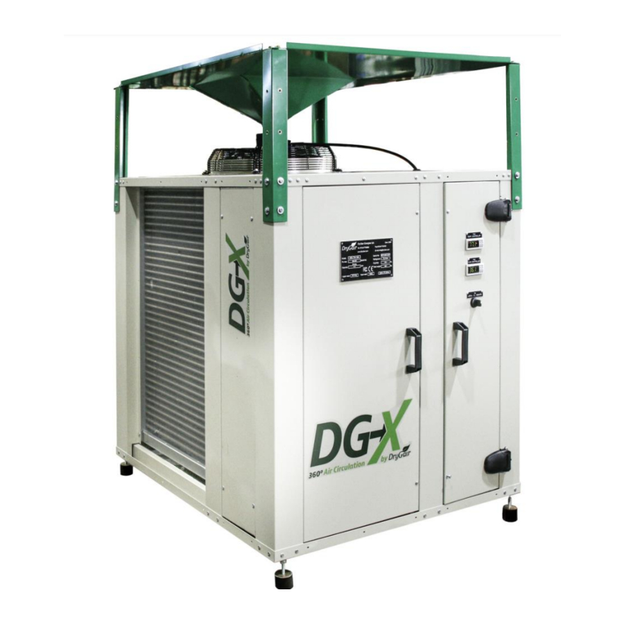
Page 12: Figure 3-1. Drygair Unit (Front And Side View)
Unit Overview Unit Description Unit Description The following figures show the various external parts of the DryGair unit. Air inlet to coils (both sides) Door to the Dehumidification Compartment Door to the electrical compartment Control panel: ▪ Temperature Controller ▪ Humidity Controller (with remote control) ▪... -
Page 13: Figure 3-2. Drygair Identification Label
• Input watt ---------- The power required by the unit (at 26°C/80°F and 60% RH) • Electricity ---------- The electricity requirements for operating the unit The following warning labels are attached to the panels of the DryGair unit. Attention high voltage... -
Page 14: Installation
Site Preparations Location Considerations 4.1.1 • The DryGair unit should be installed indoors in a closed structure and located in an accessible location for operation and maintenance. • The unit should preferably be positioned in the center of the room, blowing air towards and above the plants (in 360 degrees). - Page 15 DryGair Dehumidification Unit Model DG-X Installation Required Utilities 4.1.2 Prepare the installation site before receiving the DryGair unit. • Prepare a concrete leveled surface or hanging construction, built according to the unit dimensions and weight (see details in Appendix A).
- Page 16 Caution The DryGair unit should be lifted only from its front or rear. Special addons for inserting a forklift are attached to the bottom of the unit. Ensure the forks are spread to the distance of the unit’s forklift addons.
-
Page 17: Figure 4-1. Forklift Addons
DryGair Dehumidification Unit Model DG-X Installation Forklift addons Figure 4-1. Forklift addons • When lifting and transporting the unit, the forklift should be placed between the forklift addons, which protect delicate parts of the unit. • It is strongly recommended to secure and fix the unit to the load bearing when lifting and transporting the unit. - Page 18 Caution If the unit is tilted during its transportation, leave the unit in its vertical position for at least 3 hours before operating. This will ensure the oil drains back to the bottom of the compressor. DryGair Energies Ltd .
-
Page 19: Figure 4-2. Dg-X Carton Package
Receiving the DryGair Unit 4.2.3 The DryGair unit is shipped in a single package, which includes all unit parts and spare parts. When the unit cannot be packed as a complete unit, as in some configurations, the additional parts will be added separately and installed on-site by an experienced technician during the installation process. -
Page 20: Table 4-1. Parts And Accessories
1. Remove the cardboard box. 2. Remove the rails (see following Figure 4-3 for reference). Parts List Received 4.3.2 The DryGair DG-X unit is supplied with the following standard items and parts. Table 4-1. Parts and Accessories Part Description Quantity... -
Page 21: Figure 4-3. Rails As Shipped
DryGair Dehumidification Unit Model DG-X Installation Connecting the Hanging Rails The DG-X unit is shipped with two L-shaped metal rails connected to the unit with screws. The rails can be used for hanging the unit from a concrete ceiling with a threaded rod and should be connected to the bottom of the unit. -
Page 22: Figure 4-5. Air Distribution Module (Hood)
Installation Configuring the Air Distribution Module (Hood) Configuring the Air Distribution Module (Hood) The DG-X Model can be configured to distribute the air in 360 degrees or to any selected side(s), as shown in the following Figure 4-5. 360° distribution... -
Page 23: Figure 4-6. Lifting The Unit
DryGair Dehumidification Unit Model DG-X Installation Transporting and Positioning the Unit The DryGair unit should be transported to its location in the room using a manual or driven forklift fitted to its weight. Figure 4-6. Lifting the unit Place the unit at the selected location according to the location considerations in section 4.1.1 above. -
Page 24: Figure 4-7. Unit Hanging From A Ceiling
• Verify the ceiling and the connecting rods can hold such a weight. • Contact your local DryGair representative or DryGair (info@drygair.com) to consult on how to hang the unit. 1. Connect four threaded rods to the corners of the two L-shaped side rails. -
Page 25: Figure 4-8. Water Drain Outlet
DryGair Dehumidification Unit Model DG-X Installation Connecting the Utilities The following procedure describes how to connect the external utilities to the DryGair dehumidification unit. Connecting the Water Drain-Pipe 4.7.1 During unit operation, water is condensed and needs to be removed from the unit. -
Page 26: Figure 5-1. Electric Door (User Interface)
Unit Parts and Components Electrical Door and Compartment UNIT PARTS AND COMPONENTS The following figures show the various parts and components of the DryGair DG-X dehumidification unit. Electrical Door and Compartment Electrical Door 5.1.1 Operating and controlling the unit is performed through the components on the electrical door and the remote control. -
Page 27: Figure 5-2. Electrical Door (From Inside)
The remote control features the four buttons as on the controller itself: , and the , which access almost all the functions Prg/mute up/down arrows provided by the instrument keypad. Figure 5-3. Remote control Pressing the remote control On/Off button can start and stop the DG-X unit operation. Ver. 12/2020... -
Page 28: Figure 5-4. Electrical Compartment
Command (EP) d. Humidity controller (EP4) Contactors a. Fan (ST1) b. Compressor (ST3) Transformer AC/DC 12V (1SK) Main power switch Timer delay for the compressor (TD1) Capacitor (70 µF) Main Terminal Block Figure 5-4. Electrical compartment DryGair Energies Ltd . -
Page 29: Figure 5-5. Hvac Compartment
DryGair Dehumidification Unit Model DG-X Unit Parts and Components Dehumidification Compartment The dehumidification compartment is located behind the unit’s left-side door. Figure 5-5. HVAC compartment Compressor 5.2.1 The compressor is located at the lower left side of the dehumidification compartment. -
Page 30: Figure 5-7. Dehumidification Components
The continuous presence of bubbles might indicate loss of refrigerant. Humidity Sensor The Humidity sensor is connected at the left air entrance to the unit. Humidity sensor Figure 5-8. Humidity sensor The sensor unit is connected inside the service compartment (upper left). DryGair Energies Ltd . -
Page 31: Figure 5-9. Axial Circulation Fan
DryGair Dehumidification Unit Model DG-X Unit Parts and Components Circulation Fan The DG-X has an axial blowing fan on the top of the unit (under the hood). Circulation fan Figure 5-9. Axial circulation fan The fan circulates the air that passes through the dehumidification unit and blows it out into the room. - Page 32 Unit Operation Operation Precautions UNIT OPERATION The operation chapter explains how to use the DryGair unit. Note Operating the unit should be done only after receiving training from the representative of DryGair. Operation Precautions Before operating the unit, verify you are familiar with the following: •...
- Page 33 1. Make sure the main switch is OFF and that unauthorized persons are not near the machine. 2. Confirm the DryGair unit is stable and leveled. 3. Confirm the air distribution module (hood) is configured according to where the unit is placed and the direction the air should blow.
- Page 34 Before opening the unit electrical compartment, ensure you are familiar with the location of the external circuit breaker to the unit. 5. Open the electrical compartment and toggle the circuit breakers to their ON position. DryGair Energies Ltd .
- Page 35 DryGair Dehumidification Unit Model DG-X Unit Operation 6. Rotate the main switch to its ON position. Powering OFF is performed when the unit is not in use, or before performing maintenance and service procedures. To power OFF, press the off button on the remote controller, OR rotate the main switch to its OFF position.
-
Page 36: Figure 6-1. Humidity Controller (And Remote Control)
The humidity controller is connected to the right-side door, enabling access to the controller setup keys when the door is closed. The DG-X unit also includes a remote control for the humidity controller. Note Configuring the humidity set-point can be done through the controller or through the remote control ( button). - Page 37 24 VAC that activate relays in the unit’s switchboard. See Appendix B for details on how to connect the DryGair unit to a climate control system and how to configure its parameters.
- Page 38 It is recommended that the first operation is performed by a qualified DryGair person or representative. Wait 2 hours after the machine is under voltage before operating. 2. Check to ensure the humidity set-points is set to the required values. The humidity can be set through the remote control and the climate control system (if applicable).
- Page 39 DryGair Dehumidification Unit Model DG-X Unit Operation Operation Notes Once the unit is operated, the unit continuously pulls the cold wet air, dehumidifies the air, and blows out drier and warmer air into the room. The desired humidity of the air is set on the humidity controller.
- Page 40 Perform the following monthly: • The daily maintenance. • Check to see if there are any oil stains/residues. If found, check to see the origin and contact your local DryGair representative. Warning Do not steam-clean the heat exchanger coils. DryGair Energies Ltd .
- Page 41 Annual Maintenance Perform the following every year: Note It is recommended the yearly inspection and maintenance is performed by a qualified DryGair person or representative and having a Refrigerant technician or electrician for assistance. • The quarterly maintenance. •...
- Page 42 Companies that provide HVAC cleaning services, which are professionally trained on cleaning and handling coils and similar components that are found in DryGair dehumidification systems, can be hired to clean the DryGair Refrigeration parts. If you choose to hire an external cleaning service, make sure they are qualified and certified and have reviewed this cleaning protocol and the operation manual.
- Page 43 DryGair Dehumidification Unit Model DG-X Maintaining the Unit Cleaning the Coils 7.5.3 Coil cleaning and disinfection should be performed along the entire coil area. Note Before you begin, check that the electrical compartment door is closed and sealed, and that the unit is disconnected from the drainage system.
-
Page 44: Figure 7-1. Removing The Drainage Pan
1. Disconnect the drainage pipe from the drainage pan. 2. Remove the drainage pan from the bottom of the unit, as depicted in the following figures. Drainage pipe Drainage pan Pan locking levers (×4) Figure 7-1. Removing the drainage pan DryGair Energies Ltd . - Page 45 DryGair Dehumidification Unit Model DG-X Maintaining the Unit 3. Prepare cleaning substances as detailed in the instructions of the cleaning substance manufacturer. 4. Apply or spray the material along the drainage pan, at a slow flow. 5. Reconnect the drainage pan and the drainage tube in reverse order to the disassembly.
- Page 46 3. Remove oil and sludge with a clean cloth. If necessary, use a paintbrush dipped in oil, or cleaning material. Caution Do not use diesel or gasoline fuel. 4. When the unit will be idle for a long period disconnect it from the power supply. DryGair Energies Ltd .
- Page 47 DryGair Dehumidification Unit Model DG-X Troubleshooting and Repairing the Unit TROUBLESHOOTING AND REPAIRING THE UNIT Troubleshooting The troubleshooting section provides malfunction symptoms, the possible cause, and what may be done to overcome. Symptom Possible Cause Remedy Check the power from the power...
- Page 48 The Compressor 8.2.1 The compressor used in the DG-X dehumidifier is a durable unit that should give many years of service. However, loss of refrigerant may result in compressor failure. Any professional refrigeration (HVAC) technician will be able to service the equipment.
-
Page 49: Figure 9-1. Unit Dimensions
DryGair Dehumidification Unit Model DG-X Appendices APPENDICES Appendix A. DG-X Unit Specifications and Dimensions A.1. Specifications Depth 3.6’ (110 cm) Dimensions Width 3.3’ (100.8) 3.2’ (100 cm) + 1.3’ (39 cm) side hood Height Weight 705 lbs. (320 kg) Optimal temp. range 55 °F–95 °F (13 °C–35 °C) -
Page 50: Figure 9-2. Climate Control Relays
Climate Control System Appendix B. Climate Control System This section describes how to connect the DryGair dehumidifier to a climate control system, for operating and controlling the unit by computer software. Note All settings in the climate control system should be performed by a climate control expert, with an understanding in communication. -
Page 51: Figure 5-6. Compressor
DryGair Dehumidification Unit Model DG-X Appendices Appendix C. Main Parts List Table 9-1. Main Parts List Description Manufacturer Model Compressor Copeland ZP70KWE-PFV Compressor's Heater Copeland 70W 240V 018-0095-00 Axial Fan Rosenberg AKSE450-4-N-A4 Humidity controller Carel IR33V9HR20 Humidity sensor Carel KFTF20UNTC10K Danfoss TGEL4.5... - Page 52 Comments and Notes COMMENTS AND NOTES The following pages are intentionally left blank and can be used for adding personal comments and notes related to the DryGair unit. DryGair Energies Ltd .
Need help?
Do you have a question about the DG-X and is the answer not in the manual?
Questions and answers