DryGair DG-6 Installation, Operation And Maintenance Manual
50 hz & eu models dehumidification units
Hide thumbs
Also See for DG-6:
- Installation, operation and maintenance manual (70 pages) ,
- Manual (46 pages)

Related Manuals for DryGair DG-6


Summary of Contents for DryGair DG-6
- Page 1 DryGair Dehumidification Unit Installation, Operation, and Maintenance Manual (50 Hz & EU Models) June 2020 Ver. 06/2020...
- Page 2 : drygair.energies Proprietary and Confidential Copyright © 2020 by DryGair Energies Ltd. All rights reserved. No part of this manual may be reproduced or copied in any form by any means- graphic, electronic, or mechanical, including photocopying, typing or information retrieval systems- without written permission of DryGair Ltd.
- Page 3 DryGair Dehumidification Unit Table of Contents TABLE OF CONTENTS Introduction _________________________________________ 1 Safety ______________________________________________ 3 Unit Overview ________________________________________ 6 Installation __________________________________________ 9 Ver. 06/2020...
- Page 4 Table of Contents Unit Parts and Components ___________________________ 22 Unit Operation ______________________________________ 32 Maintaining the Unit __________________________________ 41 Troubleshooting and Repairing the Unit _________________ 47 DryGair Energies Ltd.
- Page 5 DryGair Dehumidification Unit Table of Contents Appendices _________________________________________ 49 10. Comments and Notes ________________________________ 92 Ver. 06/2020...
-
Page 6: Table Of Contents
List of Figures LIST OF FIGURES Figure 2-1. DryGair Identification label __________________________________________ 5 Figure 3-1. DryGair unit (front view) ____________________________________________ 8 Figure 3-2. DryGair unit (rear view) ____________________________________________ 8 Figure 4-1. Transferring the unit ______________________________________________ 14 Figure 4-2. Compressor transport locks after removal _____________________________ 16 Figure 4-3. - Page 7 DryGair Dehumidification Unit List of Tables LIST OF TABLES Table 4-1. Parts and Accessories ____________________________________________ 15 Table 9-1. Main Parts List __________________________________________________ 91 Ver. 06/2020...
-
Page 9: Introduction
Before You Begin Before you begin working with the DryGair dehumidification unit, read this manual. The DryGair dehumidification Operation and Maintenance Manual provides information and procedures for installing and operating the unit, as well as maintenance, troubleshooting, and repair procedures. - Page 10 Information given in a “caution” message refers to the safe operation of the unit and provides a warning where the possibility for damage to the equipment exists. Note Information given in a note describes how the part/unit functions or provides a tip on how best to use it. DryGair Energies Ltd.
-
Page 11: Safety
DryGair Dehumidification Unit Safety SAFETY DryGair Energies Ltd. believes that the safety of personnel working with and around the unit is the most important consideration. The DryGair unit is equipped with all the safety devices necessary to ensure risk-free use under standard conditions. - Page 12 Secure electrical wires and cables to prevent damage. • The protecting doors and covers should not be opened during machine • operation. Replace all safety shields after completing set-up, troubleshooting and • maintenance procedures. DryGair Energies Ltd.
-
Page 13: Figure 2-1. Drygair Identification Label
• Input watt ---------- The power required by the unit (at 18°C and 80% RH) • Total weight ------- The overall weight of the unit The following warning labels are attached to the panels of the DryGair unit. Attention high voltage... -
Page 14: Unit Overview
Unit Overview Standard Features UNIT OVERVIEW The DryGair dehumidifying unit is designed and manufactured by DryGair Energies Ltd. The unit is designed for the dehumidification of greenhouses and can also be used in any other closed structure. The unit reduces the humidity in the greenhouse according to a defined set-... - Page 15 DryGair Dehumidification Unit Unit Overview Options The DryGair unit can include one or more of the following options: Side/ One-direction Canopy – a canopy that distributes the air in one • or two specific directions. Combined Heating and Cooling – a water-based coil for heating or •...
-
Page 16: Figure 3-1. Drygair Unit (Front View)
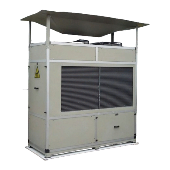
Unit Overview Unit Description Unit Description The following figures show the various external parts of the DryGair unit. Note The front and rear views are of different models and configurations. Air inlet to coils Removable cover to the compressor Door to the electrical... -
Page 17: Installation
For split type units, see details in Appendix D.2 Site Preparations 4.1.1 Location Considerations The DryGair unit should be installed inside a greenhouse and located in • an accessible location for operation and maintenance. The unit should preferably be positioned in the center of the greenhouse, •... - Page 18 • Specifications for the shut-off switch are as follows: DG-12 – 3×40 Amp. DG-12 EU – 3×63 Amp. DG-6 – 3×24 Amp. DG-6 EU – 3×32 Amp. DG-13 – 3×63 Amp. Prepare drainage for removal of the water that is condensed by the unit.
- Page 19 When using a forklift, be sure not to damage the compressor. Caution The DryGair unit should be lifted only from its front or rear. A “LIFT” notice is attached to the front and rear panels of the unit. Ensure the forks are spread sufficiently apart to ensure the stability of the load.
- Page 20 4. Protect the coils with polystyrene or plywood. Caution If the unit is tilted during its transportation, leave the unit in its vertical position for at list 3 hours before operating. This will ensure the oil drains back to the bottom of the compressor. DryGair Energies Ltd.
- Page 21 Do not break, do not open the packing with sharp tools and do not perforate the cover. When possible, the DryGair unit is shipped in a single package, which includes all unit parts and spare parts. When the unit cannot be packed as a...
-
Page 22: Figure 4-1. Transferring The Unit
Installation Unpacking the Unit Unpacking the Unit The DryGair unit should be transferred to its location in the greenhouse using a manual or driven forklift fitted to its weight and placed on the prepared flat surface. Figure 4-1. Transferring the unit 4.3.1... - Page 23 DryGair Dehumidification Unit Installation 4.3.2 Parts List Received The DryGair dehumidification unit is supplied with the following standard items and parts. Table 4-1. Parts and Accessories Part Description Quantity Main Unit Air Distribution Module (Canopy) Accessories*: Rubber pads (shock-absorbing and leveling)* ...
-
Page 24: Figure 4-2. Compressor Transport Locks After Removal
1. Loosen the nuts securing the compressor just to the point the securing braces can be removed. 2. Remove the four (4) braces surrounding the compressor springs. Figure 4-2. Compressor transport locks after removal DryGair Energies Ltd. -
Page 25: Figure 4-3. Air Distributor Module (4-Way Canopy)
4.5.1 Four-Direction Canopy The four-direction canopy distributes the air coming from the unit to four directions. This canopy type is efficient when the DryGair unit is positioned in the center of the greenhouse, away from the greenhouse walls. Note The four-direction canopy is not symmetric. Connect the canopy with its moderate slope towards the unit right side (when viewing from the front). - Page 26 2. Ensure the air distribution is directed towards the center of the greenhouse. 3. Connect it to the unit frame, using the supplied brackets and screws. 4. Ensure the module is tightly secured and that its height is just below the thermal screen (if it exists). DryGair Energies Ltd.
-
Page 27: Figure 4-4. Water Drain Outlet
5. Route the drainage to the water collection location. The water can be used for other purposes, such as hydroponic systems. After the unit is installed, call your electrician and the local DryGair technician to complete unit installation and to perform first unit activation. -
Page 28: Figure 4-5. Electrical Switchboard And Electricity Terminal Block
The unit experiences motion during transportation. Tighten all screws in the electrical switchboard, before connecting the electrical main supply cable. 2. Identify the grid connection terminal. L1 L2 L3 N Grnd Figure 4-5. Electrical switchboard and electricity terminal block DryGair Energies Ltd. -
Page 29: Figure 4-6. Hole For Main Power Cable
DryGair Dehumidification Unit Installation 3. Remove the wires routing channel cover (see Figure 4-7 for reference), and thread the main power cable through the hole in the left bottom corner of the electric compartment. Figure 4-6. Hole for main power cable 4. -
Page 30: Unit Parts And Components
Unit Parts and Components Temperature and Humidity Sensor UNIT PARTS AND COMPONENTS The following figures show the various parts and components of the DryGair dehumidification unit. Temperature and Humidity Sensor The Temperature and Humidity sensor is connected at the air entrance to the unit. -
Page 31: Figure 5-3. Defrost Temperature Sensor
DryGair Dehumidification Unit Unit Parts and Components Defrost Temperature Sensor The defrost temperature sensor measures the temperature of the coil and its surroundings. It is positioned between the front heating coils and the air entrance fins. Only its connecting cable is visually seen. -
Page 32: Figure 5-4. Electrical Compartment
5. Temperature and humidity controllers 6. Fault signal lights 7. Phase failure/sequence relay (NV relay) 8. Compressor circuit breaker (E3) The following figures show the main components in the electrical compartment, marked in the above Figure 5-4. DryGair Energies Ltd. - Page 33 DryGair Dehumidification Unit Unit Parts and Components Main power switch Turns the unit On and Off. Fan contactors Provide power to the fans. Mode selection switch (SW1) Switches between Local and Remote control. Compressor contactors (ST31 and ST32) Provide power to the compressor.
- Page 34 Green/Red signal lights Indicates unit fault. Phase failure/sequence relay (NV relay) A relay that operates when the voltage is lost. Compressor circuit breaker (E3) It provides power to the compressor. DryGair Energies Ltd.
-
Page 35: Figure 5-5. Compressor (Front View)
DryGair Dehumidification Unit Unit Parts and Components Compressor The compressor is located behind the removable front left cover. Compressor transportation spring locking braces (×4) Figure 5-5. Compressor (front view) The compressor is mounted on spring-type vibration eliminators, which are supplied by the compressor manufacturer. -
Page 36: Figure 5-7. Oil Pressure Protector And Switches
Behind the left-side cover are the oil pressure protector and two pressure switches. Compressor oil-compression safety switch. High-pressure switch Low-pressure switch Figure 5-7. Oil pressure protector and switches Caution Do not change their settings; they were tested and adjusted at the factory. DryGair Energies Ltd. -
Page 37: Figure 5-8. Service Compartment (Dg-12)
DryGair Dehumidification Unit Unit Parts and Components Service Compartment The service compartment is located behind the right-side cover. Figure 5-8. Service compartment (DG-12) Note The service compartment is different in units with the Heating and Cooling option (see Appendix D section D.1). -
Page 38: Figure 5-10. Service Compartment (Dg-12 Eu)
Unit Parts and Components Service Compartment Figure 5-10. Service compartment (DG-12 EU) Expansion valve (×2) Expansion valve controller Figure 5-11. Electronic Expansion valve (DG-12 EU) Note The EU models utilize refrigerant gas type R513a. DryGair Energies Ltd. -
Page 39: Figure 5-12. Sight Glass
DryGair Dehumidification Unit Unit Parts and Components Sight glass (×2) Figure 5-12. Sight glass The sight glass has a center indicator. Its color provides an indication to the refrigerant in the coils: Green (OK) if dry. • Yellow (Fault) if wet. -
Page 40: Unit Operation
Unit Operation Operation Precautions UNIT OPERATION The operation chapter explains how to use the DryGair unit. Note Operating the unit should be done only after receiving training from the representative of DryGair. Operation Precautions Before operating the unit, verify you are familiar with the following: The locations of the main shut off switches in case of emergency. - Page 41 1. Make sure the main switch is OFF and that unauthorized persons are not near the machine. 2. Confirm the DryGair unit is stable and leveled. 3. Confirm the air distribution module (canopy) is installed and secured. 4. Confirm the drainage pipe installed and routed away from the unit.
- Page 42 3. Rotate the main switch to its ON position. Powering OFF is performed when the unit is not in use, or before performing maintenance and service procedures. To power OFF, rotate the main switch to its OFF position. DryGair Energies Ltd.
-
Page 43: Figure 6-1. Humidistat Controller
6°C, the defrost cycle of that hour is not performed. Caution Do NOT change these values without consulting DryGair Ltd. For details on how to change and set the Humidity and Temperature values, see the documentation of the Controllers on the manufacturer's website. - Page 44 • software and 24 VAC that activate relays in the unit switchboard. See Appendix E for details on how to connect the DryGair unit to a climate control system and how to configure its parameters. It should be noted that even in the Remote mode, the unit stops working when the external temperature sensor measures 10°C and goes through a...
- Page 45 The following chapter provides basic operation guidelines for using the DryGair dehumidifying unit. DryGair is designed to control humidity according to the night plant-transpiration rate, to allow maximum efficiency for the grower. . On cloudy/rainy days the outside air is humid, which makes * AS NEEDED ventilation less effective;...
- Page 46 In the case of cloudy or rainy days, when the outside air is humid, it is possible to operate the DryGair around the clock and ventilate as little as necessary in order to reach optimum levels.
- Page 47 It is recommended that the first operation is performed by a qualified DryGair person or representative. Wait 2 hours after the machine is under voltage before operating. 2. Check to ensure the temperature and the humidity set-points are set to the required values.
- Page 48 10°C the unit goes through a 7-minute defrost cycle every hour if the measured coil temperature is below 6°C. The sequence can be changed only by the DryGair technician. The coil temperature sensor is set to around 6°C (dest. Temp.). When the temperature is above this value the unit does not go into the defrost mode.
-
Page 49: Maintaining The Unit
Perform the following monthly: The daily maintenance. • Check to see if there are any oil stains/residues. If found, check to see the • origin and contact your local DryGair representative. Warning Do not steam-clean the heat exchanger coils. Ver. 06/2020... - Page 50 Annual Maintenance Perform the following every year: Note It is recommended the yearly inspection and maintenance is performed by a qualified DryGair person or representative and having an HVAC person or electrician for assistance. The quarterly maintenance. • Paint damaged or chipped body paint to preserve the unit body.
- Page 51 Companies that provide HVAC cleaning services, which are professionally trained on cleaning and handling coils and similar components as found in DryGair dehumidification systems, can be hired to clean the DryGair HVAC parts. If you choose to hire an external cleaning service, make sure they are qualified and certified and have reviewed this cleaning protocol and the operation manual.
- Page 52 Accessing the internal coils requires dismantling and removing the fans on the roof of the unit. Access to the coils is from the top of the unit. Otherwise, only the external half of the unit can be accessed. Follow the above procedure for cleaning the internal coils. DryGair Energies Ltd.
- Page 53 DryGair Dehumidification Unit Maintaining the Unit 7.5.4 Cleaning the Drainage Basin Note Before you begin the cleaning procedure, disconnect the drainage pipe from the drainage basin. 1. Disconnect the drainage pipe from the drainage basin. 2. Remove the unit’s coil access covers and doors, located on the right and left sides of the unit beside the coils.
- Page 54 3. Remove oil and sludge with a clean cloth. If necessary, use a paintbrush dipped in oil, or cleaning material. Caution Do not use diesel or gasoline fuel. 4. When the unit will be idle for a long period disconnect it from the power supply. DryGair Energies Ltd.
-
Page 55: Troubleshooting And Repairing The Unit
DryGair Dehumidification Unit Troubleshooting and Repairing the Unit TROUBLESHOOTING AND REPAIRING THE UNIT Troubleshooting The troubleshooting section provides malfunction symptoms, the possible cause, and what may be done to overcome. Symptom Possible Cause Remedy Check the power from the power... - Page 56 Troubleshooting and Repairing the Unit Repairing the Unit Repairing the Unit If any of the electrical components fail, contact the factory Service Center to obtain the proper replacement part. For further information, contact DryGair at: Email: info@drygair.com Website: www.drygair.com 8.2.1...
- Page 57 DryGair Dehumidification Unit Appendices APPENDICES Appendix A. Standard Units Specifications (R507 Refrigerant) Unit Specifications are also available online: https://drygair.com/dehumidifiers/ A.1. DG-12 Standard Unit Ver. 06/2020...
- Page 58 Appendices Standard Units Specifications (R507 Refrigerant) A.2. DG-6 Small Unit DryGair Energies Ltd.
- Page 59 DryGair Dehumidification Unit Appendices A.3. DG-12 Standard Split Unit Ver. 06/2020...
- Page 60 Appendices Standard Units Specifications (R507 Refrigerant) A.4. DG-6 Small Split Unit DryGair Energies Ltd.
- Page 61 DryGair Dehumidification Unit Appendices A.5. DG-12 Standard Unit with Heating & Cooling Ver. 06/2020...
- Page 62 Appendices Standard Units Specifications (R507 Refrigerant) A.6. DG-6 Small Unit with Heating & Cooling DryGair Energies Ltd.
- Page 63 DryGair Dehumidification Unit Appendices A.7. DG-12 Standard Split Unit with Heating & Cooling Ver. 06/2020...
- Page 64 Appendices Standard Units Specifications (R507 Refrigerant) A.8. DG-6 Small Split Unit with Heating & Cooling DryGair Energies Ltd.
- Page 65 DryGair Dehumidification Unit Appendices A.9. DG-13 Warm Climate Unit Ver. 06/2020...
- Page 66 Appendices EU Models Specifications (R513a Refrigerant) Appendix B. EU Models Specifications (R513a Refrigerant) Unit Specifications are also available online: https://drygair.com/dehumidifiers/ B.1. DG-12 EU Standard Unit DryGair Energies Ltd.
- Page 67 DryGair Dehumidification Unit Appendices B.2. DG-6 EU Small Unit Ver. 06/2020...
- Page 68 Appendices EU Models Specifications (R513a Refrigerant) B.3. DG-12 EU Standard Split Unit DryGair Energies Ltd.
- Page 69 DryGair Dehumidification Unit Appendices B.4. DG-6 EU Small Split Unit Ver. 06/2020...
- Page 70 Appendices EU Models Specifications (R513a Refrigerant) B.5. DG-12 EU Standard Split Unit with Heating & Cooling DryGair Energies Ltd.
- Page 71 DryGair Dehumidification Unit Appendices B.6. DG-6 EU Small Unit with Heating & Cooling Ver. 06/2020...
- Page 72 Appendices EU Models Specifications (R513a Refrigerant) B.7. DG-12 EU Standard Split Unit with Heating & Cooling DryGair Energies Ltd.
- Page 73 DryGair Dehumidification Unit Appendices B.8. DG-6 EU Small Split Unit with Heating & Cooling Ver. 06/2020...
-
Page 74: Figure 9-1. Four-Direction Canopy
The four-direction canopy option distributes the air coming from the unit to four directions. This type of canopy is efficient when the DryGair unit is positioned in the center of the greenhouse, away from the greenhouse walls. Figure 9-1. Four-direction canopy The 4-way canopy is not symmetric. -
Page 75: Figure 9-2. Air Distributor Module (4-Way Canopy)
DryGair Dehumidification Unit Appendices Moderate slope Figure 9-2. Air distributor module (4-way canopy) Ver. 06/2020... -
Page 76: Figure 9-3. Side Canopies (Different Orientations)
C.2. Side Canopy The side canopy option distributes the air coming out of the unit in chosen directions. This configuration is efficient when the DryGair unit is positioned at the sides of the greenhouse, near the greenhouse walls. Note Make sure to place the unit with a minimum distance of 50 cm from the greenhouse wall, to allow airflow into the rear coils. -
Page 77: Figure 9-4. Air Distribution Panel
This small one-direction canopy option is separately connected above each fan, blowing the air in one direction. This type of canopy is efficient when the DryGair unit is positioned in a narrow or long-narrow location. Figure 9-4. Air distribution panel... -
Page 78: Figure 9-5. Air Heating Option
(see details in Appendix E.2). Details on setting the temperature of the controller can be found on the controller's manufacturer website (https://www.carel.com/product/ir33-din). Video instructions on the heating and cooling unit can be found in https://www.youtube.com/watch?v=c71uSnCSsHE&list=PL4DgRhaYl- hBTk8vjpa_QAQzeNZJyRyIL&index=1 DryGair Energies Ltd. -
Page 79: Figure 9-6. Temperature Valve Controller
D.1.1. Connecting the Hot and Cold Water-Source to the Unit 1. Make sure the external water supply you are connecting to the unit provides water under the conditions specified by the DryGair team. 2. Connect the external hot/cold water supply, using 1.25" BSP male connections. - Page 80 ” to permanently save the new set point. 4. The display will return to showing the current temperature. For instructions on how to control the heating or cooling function remotely through a climate control system, see Appendix E.2. DryGair Energies Ltd.
-
Page 81: Figure 9-7. Drygair Split Unit
DryGair Dehumidification Unit Appendices D.2. Split Units For locations with operative or location special requirements, the DryGair unit can be separated into two parts. Note The two sections must be placed no farther than 4 meters apart. The DryGair split unit includes two sections: Lower section –... -
Page 82: Figure 9-8. Connecting Copper Tubes (Lower Section)
Discharge tube (red): 1⅛" dia. tube. In EU models: 1⅝" dia. • Suction tube (blue and usually isolated): 1⅝" dia. tube. In EU models: • 2⅛" dia. The tubes include a Schrader valve that is used for the connecting procedure. DryGair Energies Ltd. -
Page 83: Figure 9-9. Tube Stop Valves - Lower Section (Left) & Upper Section (Right)
DryGair Dehumidification Unit Appendices D.2.1. Connecting the Unit Sections On the upper and lower sections of each tube is a valve inside the unit. Its purpose is to prevent refrigerant leakage from the unit sections during transportation and before connecting the two sections at the customer’s site. - Page 84 If a leak is found- fix it. 4. Evacuate the Nitrogen from the tested section and remove the remaining air with a vacuum pump; until it is completely empty. 5. Open the stop valves of both sections of the unit. DryGair Energies Ltd.
-
Page 85: Figure 9-10. Electrical Cables
DryGair Dehumidification Unit Appendices D.2.1.2. Connecting the Electrical Cables Caution All electrical connections must be performed by a certified electrician. To connect the electrical cables: 1. Open the service compartment door on the right side of the upper unit and release the electrical cables: Two green cables that are connected to the axial fans. -
Page 86: Figure 9-12. Brown Terminal Block (50-56)
See wire connections by color code in the following Figure 9-12. 50 – Black 51 – White and Red 52 – Orange 53 – Brown 54 – Blue 55 – Grey 56 – Purple Figure 9-12. Brown terminal block (50–56) DryGair Energies Ltd. -
Page 87: Figure 9-13. Water Drainage
DryGair Dehumidification Unit Appendices D.2.2. Connecting the Drainage Water is condensed during unit operation and needs to be removed from the unit. In some environments, depending on the air temperature and humidity, this could be a large quantity of water. -
Page 88: Figure 9-14. Unit With Heating/Cooling
The water connections should be done by a certified plumber or by a qualified piping person. Connect the hot/cold water inlet and outlet supply pipes to the unit valves. They have an internal pipe threading of 1¼" BSP. DryGair Energies Ltd. -
Page 89: Figure 9-15. Climate Control Relays
Appendices Appendix E. Climate Control System This section describes how to connect the DryGair dehumidifier to a climate control system, for operating and controlling the unit by computer software. Note All settings in the climate control system should be performed by a climate control expert, with an understanding of communication. - Page 90 E.2.1. Humidity Control Connect the DryGair unit to the climate control system as described in section E.1 above. E.2.2. Temperature Control The temperature control is based on the DryGair unit’s temperature sensor.
-
Page 91: Figure 9-16. Temperature Valve Controller
DIN rail at the lower right part of the electrical compartment. Figure 9-16. Temperature valve controller Controlling the DryGair unit with a heating/cooling configuration by a climate control system requires connecting a serial communication card (IROPZSER30) to the temperature valve controller. -
Page 92: Figure 9-18. Controller Cover Centerpiece
Appendices Climate Control System To connect the Serial Communication Card to the Temperature Valve Controller 1. Power off the DryGair unit. 2. Remove the Serial Card cover from the temperature valve controller. Cover centerpiece Figure 9-18. Controller cover centerpiece 3. Break off the cover centerpiece. - Page 93 DryGair Dehumidification Unit Appendices E.2.2.3. Setting the Temperature Valve Controller Serial Address Connecting the temperature valve controller to a climate control system requires setting an address for the controller and assigning it in the climate control system to communicate with the temperature valve controller.
- Page 94 Appendices Climate Control System E.2.2.4. Modbus Parameters Transmitting information between the DryGair temperature valve controller and the climate control system is done by Modbus (communication protocol). Following are the controller parameters and their corresponding Modbus parameters for the climate control system: –...
- Page 95 DryGair Dehumidification Unit Appendices E.2.2.5. List of Carel ir33 Parameters The following is a list of parameters from the CAREL ir33 User Manual. Ver. 06/2020...
- Page 96 Appendices Climate Control System DryGair Energies Ltd.
- Page 97 DryGair Dehumidification Unit Appendices Ver. 06/2020...
- Page 98 Appendices Climate Control System DryGair Energies Ltd.
- Page 99 Main Parts List Table 9-1. Main Parts List Description Manufacturer Model Compressor Copeland For DG-12: 3DS5-150X-AWMD For DG-12 EU: 4MT1-22X-AWM/D For DG-6: ZB58KCE For DG-6 EU: ZB114KCE Axial Fan Rosenberg AKFD 710-6-6-K 6H A4 Humidity Controller Carel IR33V9HR20 Temp Controller Carel PZD2S0P001...
- Page 100 Comments and Notes COMMENTS AND NOTES The following pages are intentionally left blank and can be used for adding personal comments and notes related to the DryGair unit. DryGair Energies Ltd.
- Page 101 DryGair Dehumidification Unit Comments and Notes Ver. 06/2020...
Need help?
Do you have a question about the DG-6 and is the answer not in the manual?
Questions and answers