
Subscribe to Our Youtube Channel
Related Manuals for Limaco ULM-31-HF

Summary of Contents for Limaco ULM-31-HF
- Page 1 OPERATION AND INSTALLATION MANUAL RADAR NON-CONTACT LEVEL TRANSMITTERS ULM-31-HF, ULM-31-HF-F, ULM-31А1, ULM-31А1-HF, ULM-31А1-HF-F, ULM-31А1-HF-F-LC.
-
Page 2: Table Of Contents
CONTENTS Document Details 1.1 Document Purpose …………………………………….... 5 1.2 Target Group …………………………………………………. 5 1.3 Symbolic Notations ……………………………………..5 Basic Safety Regulations 2.1 Requirements for Personnel ………………………………….. 6 2.2 Purpose ………………………………………………………. 6 2.3 Operational Safety …………………………......8 2.4 General Guidelines on Safety ………………………………... 8 2.5 Environmental Safety ………………………………………... - Page 3 Electrical Connection 5.1 General Guidelines …………………………………………... 30 5.2 Connecting Cable ……………………………………………. 30 5.3 Shielding and Earthing ………………………………………. 31 5.4 Purpose of Terminals. Connection. ………………………….. 32 5.5 Power supply ………………………………………….... 38 5.6 Device Connection Procedure ……………………………….. 40 Initial Setup and Commissioning 6.1 Level Transmitter Address Setup …………………………….
- Page 4 12.5 Mounting of ULM-31А1 level transmitter at the stub tube …. 74 12.6 Mounting of ULM-31-HF-F, ULM-31А1-HF-F, ULM-31А1- HF-F-LC level transmitters at the stub tube ………………… 12.7 Mounting of ULM-31-HF, ULM-31А1-HF level transmitters at the stub tube ………………………………………………. 12.8 Mounting of ULM-31А1 level transmitter at the stub tube with insulating spacer………………………………………..
-
Page 5: Document Details
1 DOCUMENT DETAILS 1.1 Document Purpose This Operation Manual includes information necessary for installation, connection, commissioning and setup, as well as guidelines on maintenance and trouble- shooting. Prior to the level transmitter installation and putting in operation it is nec- essary to familiarize with instructions set forth herein. -
Page 6: Basic Safety Regulations
When operating the equipment, the personnel shall use the required personal protec- tion equipment in compliance with the standards at the enterprise. 2.2 Purpose The level transmitters ULM-31А1, ULM-31-HF, ULM-31А1-HF, ULM-31-HF-F, ULM-31А1-HF-F and ULM-31А1-HF-F-LC (hereinafter referred to as the “level transmitters”) are designed to continuously contactlessly measure the level of liquid, viscous or bulky products and intended for use in the process metering systems. - Page 7 Analog output 4-20 Maximal power con- sumption,W Minimal number of wires Body Alumi- material nium cast- ing alloy Polyamide Configuration by HART-modem Configuration by HART- communicator Getting readings by HART Produced now Recommended ap- Tech- Techno- High High Tech- Techno- Techno- Technolo- plication...
-
Page 8: Operational Safety
2.4 General Guidelines on Safety The level transmitters ULM-31А1, ULM-31-HF, ULM-31-HF-F, ULM-31А1-HF, ULM-31А1-HF-F and ULM-31А1-HF-F-LC satisfy all current safety requirements and standards. Depending on the version, the working emission frequency of the level transmitters makes approximately 24 GHz for ULM-31А1 and 125±5 GHz for... -
Page 9: Product Description
3 PRODUCT DESCRIPTION 3.1 Level Transmitter Scope of Supply. The scope of supply includes: - The radar level transmitter (ULM-31-HF, ULM-31А1, ULM-31А1-HF, ULM-31- HF-F, ULM-31А1-HF-F, ULM-31А1-HF-F-LC); - The setup software and the documentation on electronic medium (compact disk CD): - The software program for Ulmcfg setup;... -
Page 10: Product Design
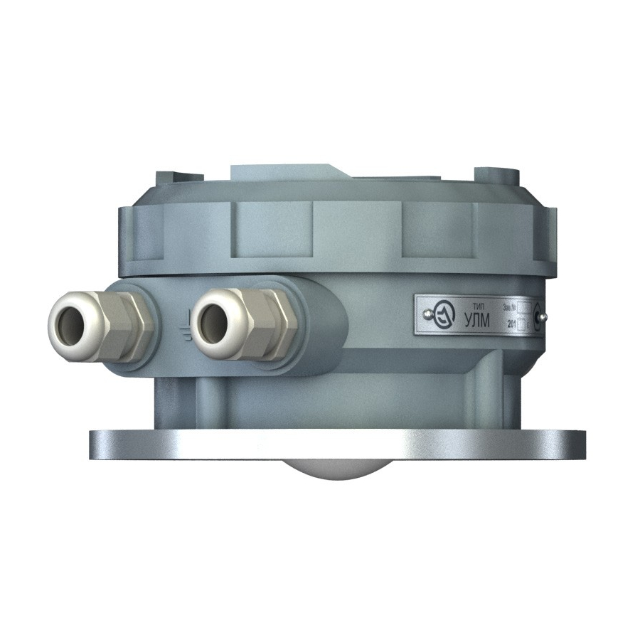
3.2 Product Design Fig. 3.1. Basic elements appearance and location for the level transmitters ULM-31-HF, ULM-31А1-HF. Fig. 3.2. Basic elements appearance and location for the level transmitter ULM-31А1. ULM.0.01.000RE_10_08_20... - Page 11 Fig. 3.3. Basic elements appearance and location for the level transmitters for the level transmitters ULM-31-HF-F, ULM-31А1-HF-F and ULM-31А1-HF-F- LC. Aluminium case. Fig. 3.4. Basic elements appearance and location for the level transmitters for the level transmitters ULM-31-HF-F, ULM-31А1-HF-F and ULM-31А1-HF-F- LC.
-
Page 12: Product Identification
Electronic module Fig. 3.5. Level Transmitter Design. Electronic Module Location. 3.3 Product Identification The device identification is performed using one of possible methods: - according to the data specified on the device nameplate (identifying plate); - according to the attached device certificate; - by the request to the manufacturer with specification of the level transmitter serial numbers. - Page 13 Examples of the common-type nameplates: Fig. 3.6. Common-type nameplate ULM-31-HF Fig. 3.7. Common-type nameplate ULM-31A1 Fig. 3.8. Common-type identifying plate ULM-31A1-HF Fig. 3.9. Common-type identifying plate ULM-31A1-HF-F Fig. 3.10. Common-type identifying plate ULM-31A1-HF-F-LC Fig. 3.11. Common-type identifying plate ULM-31-HF-F ULM.0.01.000RE_10_08_20...
-
Page 14: Operating Principle
3.4 Operating Principle The level transmitter is installed on the tank roof, onto the pipe branch flange. However, no transmitter’s part is dipped inside the tank. The device measures the distance L from the antenna shield (para. 12.13) to the product surface via the opening in the flange. - Page 15 Fig. 3.13. Measuring Principle. The level transmitters uses a FMCW principle of operation—the radio locator prin- ciple. This is one of classical methods for non-contact measuring of the distance, which allows minimizing the effect of stray interferences and interferences related to irregularities (disturbances) of the measured product surface.
-
Page 16: Packaging, Transportation And Storage
Fig. 3.14. LFM-radio locator operating principle 3.5 Packaging, Transportation and Storage The level transmitter is supplied in the package, which ensures its protection during transportation. The package is made of cardboard, which is a recyclable material. In certain cases it is possible to use polyethylene foam and polyethylene film, which are disposed of at dedicated processing enterprises. -
Page 17: Installation
4. INSTALLATION 4.1 Selection of Installation Position The level transmitter stability of readings and the product precision of measuring depend on its correct installation. When selecting the installation position, the following recommendations should be adhered to: - to install the device in such way that in the measurement zone there are no sub- jects and structures making interferences to the radio wave beam propagation (pipes, valves, stirrers, tank walls, etc. - Page 18 Fig. 4.2. Device Installation on Tank. Product Feeding. - during product discharge from the tank, the swirl can be formed on the product surface. This shall be considered when selecting the device location. The level transmitter shall be installed above the location with the smoothest product surface. Fig.
- Page 19 - to provide the level measurement over the total depth of the tank, the level trans- mitter shall be oriented in direction of the tank lowest point. In the vertical cylindri- cal hoppers with the cone-shaped outlet, this is achieved by its installation in the center of the hopper roof.
- Page 20 Fig. 4.5. Device Installation with Inclination on Hopper with Cone-Shaped Bottom. The values of distances V from the tank center to installation position are given in the following Table. 2 4 6 8 ...
- Page 21 For example. With the hopper is 15 m high, is mounted at 1.6 m distance fro the center. Using the Table, let us determine the required inclination angle 6˚. - for device protection against direct sunlight in conditions of hot climate, the pro- tection screen or the shed should be used;...
- Page 22 Fig. 4.7. Device Installation - if the tank walls are not smooth (for example, corrugated metal, welded joints, structures), the distance from the wall shall be the longest possible. NOTE In case of using the device on the tanks made of non-conductive material (for ex- ample, plastics), it should be taken into consideration that the structures outside the tank may hit in the measuring beam.
-
Page 23: General Requirements For Installation On Mounting Pipe
Fig. 4.8. Device Installation. Tank Made of Non-Conductive Material. 4.2 General Requirements for Installation on Mounting Pipe Branch Fig. 4.9. Device Installation on Mounting Pipe Branch. ULM.0.01.000RE_10_08_20... -
Page 24: Mounting Branch Pipes
The pipe branch inner diameter D shall be at least 100 mm . The pipe branch axis permissible vertical deviation, ONLY during measuring the level of LIQUID prod- ucts - 1°. The pipe branch height H is measured along its inner surface from the flange to the opening lower edge. -
Page 25: Measuring Beam Zone Of Action
Pipe branch diameter (mm) Maximal permissible height (mm) Requirements for pipe branch and the opening in the roof for application with low- power reflected signal. Mounting pipe branch height shall be no higher than its diameter: H For these applications it is not recommended to use the pipe branches with the height above 250 mm. -
Page 26: Dead Zone
Fig. 4.10. Measuring Beam Zone of Action 4.5 Dead Zone The level transmitters have the so-called “dead zone”. This zone is close to the sen- sor antenna. Its measuring is either difficult or impossible. The “dead zone” is shown in Fig.4.11 and it may be conventionally divided into three regions. The closest region (in the Figure on the left), which is impossible to measure. -
Page 27: Examples For Installation
4.6 Examples for Installation The examples for the level transmitter installation designed in accordance with this instruction requirements are shown in Fig. 4.12 in positions А and B. Installation of the level transmitter on the tank flange without using the pipe branch is shown in Fig. - Page 28 Fig. 4.12. Examples of Installation ULM.0.01.000RE_10_08_20...
-
Page 29: Structures In Tank
4.7. Structures in Tank The structures located in the tank - tubes, valves, stirrers, tank corrugated walls, level alarms and other subjects may be the sources of the stray signal. The installa- tion position of the level transmitter shall be selected so, that there are no obstacles on the radio signal propagation way. -
Page 30: Electrical Connection
5. ELECTRICAL CONNECTIONS 5.1 General guidelines WARNING All connection operations must be performed with disconnected power. Skilled personnel having permit for this type works must only be allowed to perform electrical connection operations. Level transmitter allows installation of two cable glands with sell-sealing NPT thread. -
Page 31: Shielding And Earthing
NOTE In order to prevent device from moisture ingress, it is recommended to bend con- necting cable downward in the immediate vicinity of cable gland for the rainwater or condensate running off. Fig. 5.1 Cable laying recommendation 5.3 Shielding and grounding. It is recommended to connect a cable shield to earth potential on one side. -
Page 32: Purpose Of Terminals. Connection
5.4 Terminal functions. Connection. Fig. 5.3 Connection of ULM-31A1, ULM-31-HF, ULM-31-HF-F, ULM-31A1-HF and ULM-31A1-HF-F level transmitters. Option 1. 1 – PC connection; 2 – RS-485/USB converter; 3 – RS-485 line shield, “earth” connection on the converter side; 4 – Control unit, for example, PLC;... - Page 33 Fig. 5.4 Connection of ULM-31A1, ULM-31-HF, ULM-31-HF-F, ULM-31A1-HF and ULM-31A1-HF-F level transmitters. Option 2. 1 – PC connection; 2 – RS-485/USB converter; 3, 6, 15 – Shield connection of the interface lines; 4 – Control unit, for example, PLC; 5 – HART-modem connection socket;...
- Page 34 Fig. 5.5 Connection of ULM-31A1, ULM-31-HF, ULM-31-HF-F, ULM-31A1-HF and ULM-31A1-HF-F level transmitters. Option 3. 12 – 24V power supply; 1– PC connection; 13 – Relay indication unit, light indica- 2– RS-485/USB converter; 3– Switch, RS-485 line matching load tion arrangement example;...
- Page 35 The ULM-31A1-HF-F-LC modification is available, which is intended for liquid level measurement. It is designed for level measurement under the simple conditions requiring neither sophisticated adjustment nor additional service func- tion. In addition, ULM-31A1-HF-F-LC radar level transmitter is equipped with the special antenna and provides the reliable measurement of liquids even in case of in- stallation in the high and small-diameter stub tubes.
- Page 36 5 – HART digital line shield; 6 – Analog display unit; 7 – 24V power supply; Fig. 5.7 Connection of the ULM-31A1-HF-F-LC modification level transmitter. Option 2. 1 – PC connection; 2 – RS-485/USB converter; 3, 6, 12 – shield connection of the interface lines; 4 –...
- Page 37 . 5.8 Connection of levelmeter ULM-31A1-HF-F-LC. 2-wire option. Power supply Loop resistance 3,4 Wire shield connection Loop current ON – factory setting ON – additional firmware of communicating processor is loading, otherwise basic firmware is loading. ON – additional firmware of calculating processor is loading, otherwise basic firmware is loading.
-
Page 38: Power Supply
5.5 Power supply It is recommended to use the stabilized DC power supply with the output voltage of В . It is allowed to connect multiple level transmitters to the same 24 ИП power supply. А Power supply must provide load current output based on per level transmitter: ... - Page 39 Maximum permissible power cable length. Wire cross- section (mm 0.25 119m 142m 166m 190m 0.35 133m 166m 200m 233m 266m 190m 238m 285m 333m 380m 0.75 285m 357m 429m 500m 571m 380m 476m 571m 666m 761m When external cable diameter exceeds maximum value permissible for the level transmitter cable gland, the use is required of terminal box connecting the level transmitter feeder cable of permissible cross-section and greater cross-section cable (mains cable).
-
Page 40: Device Connection Procedure
5.6 Device connection procedure WARNING - safety regulations adopted at the enterprise must be strictly observed; - all operations must be performed with disconnected supply voltage. - make sure that supply voltage complies with device specifications. - prior to voltage supply, device external ground terminal must be connected. Required tools: - minus screwdriver 3mm;... - Page 41 CAUTION Missing or damaged sealing ring impairs the device ingress protection and can result in its failure. 4. Strip the cable of external insulation. When using shielded cable, remove shield. 5. Strip wires of insulation 4-6mm from end. When using multiconductor wires, it is recommended to crimp bare ends with lugs.
- Page 42 Upon the connection completion, it is recommended to conduct the completed work quality inspection with regard to the following items: - if there are any cable damages; - if there are any mechanical stresses due to the cable tension; - cable glands are properly installed, tightened and sealed; - device casing cover is installed and tightened.
-
Page 43: Initial Setup And Commissioning 6.1 Level Transmitter Address Setup
6. INITIAL SETTING AND COMMISSIONING Device setting prior to commissioning can be carried out as follows: 1) by means of PC via RS-485 interface (Modbus RTU data communications protocol, for protocol details, see “ULM transmitter data communications protocol”) and ulmcfg configuration utility software; 2) by means of PC via НАRT interface;... -
Page 44: Connection To Pc Via Interface Rs-485
6.2 PC connection via the RS-485 interface. The digital interface provides user access to the level transmitter readings and ena- bles level transmitter setting and diagnostics. The level transmitter digital interface is implemented as a two-wire serial RS-485 line. Modbus RTU data communica- tions protocol. - Page 45 the work start. Should that be the case, set as follows: transmission rate – 9600bps, parity – Even, number of data bits – 8, number of stop bits – 1 or 2. CAUTION After the interface converter connection to USB, install the device driver where necessary.
- Page 46 Fig. 6.5 RS-485 line “Star” laying method Low transmission rate of 9600 bps used in level transmitter provides good interfer- ence immunity of communications line and allows application of various cable lay- ing options including so-called “star” method shown in Fig. 6.5. User can choose the suitable laying option based on cable laying ease and length minimization con- siderations.
-
Page 47: Setup Of Device Basic Parameters Using Pc Via Rs-485
6.3. Setting of main level transmitter parameters from PC via RS-485. Minimum PC requirements: Pentium II, RAM 256 MB, display 800х600, USB or COM port, OS Windows 95 or later. The “CONFIGURATOR” (ULMCFG) software is used for level transmitter setting. Program functionality: - main level transmitter (hereinafter referred to as "transmitter") settings retrieval and change;... - Page 48 ‘ENTER’ key or click ‘OK’ button. Fig. 6.8 Device search field Level transmitter parameters are configured before delivery based on the data indi- cated by customer in the configuration data sheet at website www.limaco.ru. Set- ULM.0.01.000RE_10_08_20...
- Page 49 (600 mm), which is optimum for the most applications. Where measure- ment of smaller distances is required, this parameter can be decreased upon agre- ment with JSC LIMACO. Importantly, the value should remain within the stable measurement range as described in para. 4.5.
- Page 50 Fig. 6.10 4-20mA current output setup “4-20mA output corresponds to” – choose whether the current signal would cor- respond to the product level in vessel or distance to the product (see Fig. 3.9). “Sensor mounting height” – input distance (Н) from transmitter mounting flange to the vessel bottom in millimeters.
- Page 51 “Don’t use a signal with amplitude less than” – minimum threshold value of sig- nal amplitude to be accepted for calculation. “Sufficient signal amplitude” is used for the device autodiagnostics with the use of echo signal amplitude as a criterion. “Time of stable signal identification”...
-
Page 52: Current Output 4-20 Ma. Setup Of Emergency Signals
6.4 4-20mA current output. Setting of alarm signals. Level transmitter is equipped with active 4-20mA current output for connection of standard receivers. Fig. 6.12 4-20mA current output connection diagram Depending on configuration, it may be set to output product level in vessel or dis- tance to the product surface readings, or 3mA, 4mA or 21mA alarm current signals. - Page 53 Fig. 6.13 Setting alarm current signals. Example in Fig. 6.13 shows that the current output delivers as follows: - 21mA at internal diagnostics of measuring section; - 3 mA when the level transmitter internal temperature is exceeded. ULM.0.01.000RE_10_08_20...
-
Page 54: Setup Of On-Off Signals
6.5 Setting of relay signals Level transmitter has two normally open groups of relay contacts. The “Configura- tor” software tab allows relay closing criteria setting. Depending on the level trans- mitter readings and measurement status value, two relay signals are generated. Fig. - Page 55 switches the corresponding channel on, whereupon three relay closing conditions become available. Two top conditions set the relay response to the first and second threshold levels. When both conditions are enabled, then Boolean operation be- tween these must be defined; in case of “AND”, relay tripping requires simultane- ous fulfillment of both conditions, in case of “OR”, relay is closed at fulfillment of either condition.
-
Page 56: Bluetooth
Android operating system. LIMACO continuously improves the ULM level transmitter software, en- hances measuring capabilities of our equipment and adapts it for new tasks of the automated control and accounting in the enterprise system. -
Page 57: Device Diagnostics
7. DEVICE OPERATION INFORMATION 7.1 Device diagnostics. “Configurator” software in the “Diagnostics” tab, Fig. 7.1, contains basic transmit- ter operation information. It is visually divided into seven panels where transmitter performance data are displayed. Most lines are displayed in black font; data falling beyond the permissible criteria or recommended conditions are displayed in red;... - Page 58 - current signal amplitude, and on the right following the “Min.:” word - amplitude criterion (“Adequate signal amplitude” in the “Configuration” tab). When amplitude is below criterion, bit 2 of the status register is set to 1. “Measuring device test” – measurement system performance indicator; on the right –...
-
Page 59: Output Signal Emulation
7.2 Output signal emulation The “EMUL.” key enabling signal emulation mode in transmitter. Fig. 7.2 Output signal emulation Output signal emulation is the debugging mode enabling current output setting and operation testing. Press the “EMUL.” key, transmitter will change to emulation mode in about 4 sec- onds. -
Page 60: Troubleshooting
8. TROUBLESHOOTING In the case of fault occurrence, personnel responsible for the level transmitter opera- tion must take remedial measures. Operation of faulty level transmitter operation is prohibited. Sources of level transmitter failure can be as follows: - measuring device failure; - data-displaying receiving device;... - Page 61 Failure Cause Remedy Signal One or more controlled pa- Connect to transmitter through PC 4-20mA corre- rameters of transmitter are or Bluetooth. Check whether alarm sponds to one beyond the permissible val- signal value matches its mask (para. of alarm val- ues: 6.4).
- Page 62 Failure Cause Remedy - low echo amplitude – ap- Record spectrum (see para. 7.3.), plication with low dielectric send it to the technical support ad- capacitance products, appli- dress. Follow the further recom- cation with bulk products, mendations. electronic unit failure - loss of signal - sharp fluc- Indicative parameter, current signal tuations of reflecting sur-...
- Page 63 Failure Cause Remedy RS-485 Necessary driver is not in- Check converter function in the PC connection stalled, or incorrect initial operating system (Device Manager), with delivery settings of the USB/RS-485 set converter as required. of the 4-20mA converter signal Transmitter Modbus Set different Modbus addresses for properly oper-...
-
Page 64: Maintenance
9. MAINTENANCE Level transmitter does not require the special maintenance. Depending on the oper- ating conditions, periodic cleaning of antenna screen surface may only be required. Do not use cleaning agents, which may be potentially corrosive for body materials, seals, caps and cable glands, for level transmitter cleaning. ULM.0.01.000RE_10_08_20... -
Page 65: Dismantling
10. DISMANTLING 10.1. Dismantling procedure The device must be dismantled with the observance of every safety regulation and standard adopted at the enterprise; exercise particular caution when working at heights and at vessels containing corrosive or toxic products. The procedure for dismantling is the reverse of the procedure described in pa- ra.. -
Page 66: Repair
Device repair is only permitted at manufacturer’s factory or authorized representa- tive offices. When equipment return to manufacturer for repair is required, please send official letter to the following e-mail: in@limaco.ru. Clean device from contaminations; pack it in the container ensuring its undamaged condition during transportation and in ‘Contacts’ section. -
Page 67: Appendices 12.1 Technical Specifications
12. ANNEXES 12.1. Specifications Name Value General data Casing material - Aluminium cast alloy, anodized, pow- der-coated - Polyamide Material of gasket between casing and Rubber compound cover Antenna screen material PTFE Bluetooh cap material PTFE Cable gland material Polyamide Weight without flange 2.5kg max 203х103х153mm... - Page 68 Electrical durability, at rated load, min- 50,000 (100,000) trips imum (standard) Device performance parameters Absolute measurement error 1 mm max for ULM-31-HF, ULM-31- HF-F; 3 mm max for ULM-31A1, ULM-31A1- HF and ULM-31A1-HF-F. 5 mm max for ULM-31A1-HF-F-LC Measurement range 0.6 m to 50 m...
- Page 69 М20х1.5 (round cross- section cable dia 8 to 13mm) – 2 pcs Screw terminals for the electric connec- 2.5 mm max (AWG 14) tion of wires with cross-section Permits and certificates Please download these documents at www.limaco.ru ULM.0.01.000RE_10_08_20...
-
Page 70: Specifications Of Levelmeter Ulm-31A1-Hf-F-Lc, 2-Wire Option
12.2 Specifications of levelmeter ULM-31A1-HF-F-LC, 2-wire option. Name Specification General information Body material Aluminium casting alloy, electroplated anodizing, powder coating Sealing material between body and cov- Rubber Antenna screen material Teflon Cable glands material Polyamide Weight without flange Not more than 2,5Kg Dimensions 203х103х153 mm Kind of mounting... - Page 71 At temperature of levelmeters flange It’s required placement radio- higher than 50˚ C transparent isolating seal 84,0…106,7 kPa (630-800 mm Hg) Atmosphere pressure Not more than 95% at 35˚ C and lower Realtive humidity in installation location of levelmeter temperatures, without moisture conden- sation -1…6 bar, it’s required placement of ra- Overpressure or underpressure in tank...
- Page 72 12.3. Mounting dimensions of level transmitter without mounting flange 4 holes M6x8-12 12.4. Level transmitter connection to mounting flange Screw M6x10 DIN 912 (4 pcs) ULM-31А1 ULM.0.01.000RE_10_08_20...
- Page 73 Screw M6x10 DIN 912 (4 pcs) ULM-31-HF, ULM-31А1-HF Screw M6x10 DIN 912 (4 pcs) ULM-31-HF-F, ULM-31А1-HF-F and ULM-31А1-HF-F-LC ULM.0.01.000RE_10_08_20...
- Page 74 12.5 Mounting of ULM-31А1 level transmitter at the stub tube ULM.0.01.000RE_10_08_20...
- Page 75 12.6. Mounting of ULM-31-HF-F, ULM-31А1-HF-F, ULM-31А1-HF-F-LC level transmitters at the stub tube ULM.0.01.000RE_10_08_20...
- Page 76 12.7. Mounting of ULM-31-HF, ULM-31А1-HF level transmitters at the stub tube ULM.0.01.000RE_10_08_20...
- Page 77 12.8. Mounting of ULM-31А1 level transmitter at the stub tube with insulating spacer ULM.0.01.000RE_10_08_20...
- Page 78 12.9. Mounting of ULM-31-HF-F, ULM-31А1-HF-F, ULM-31А1-HF-F-LC level transmitters at the stub tube with insulating spacer ULM.0.01.000RE_10_08_20...
- Page 79 12.10. Mounting of ULM-31А1, ULM-31-HF-F, ULM-31А1-HF-F, ULM-31А1- HF-F-LC level transmitters at the stub tube with insulating spacer with the use of clamping flange 1 Level transmitter 2 Adapter flange 3 Insulating spacer 4 Clamping flange 5 Tank flange ULM.0.01.000RE_10_08_20...
- Page 80 12.11. Mounting of ULM-31-HF, ULM-31А1-HF level transmitters at the stub tube with insulating spacer with the use of clamping flange 1 Level transmitter 2 Adapter flange 3 Spacer ring 4 Clamping flange 5 Insulating spacer 6 Tank flange ULM.0.01.000RE_10_08_20...
- Page 81 12.12. Mounting of ULM-31-HF-F, ULM-31А1-HF-F, ULM-31А1-HF-F-LC level transmitters at the small diameter stub tube with the use of reducing piece 1 Level transmitter 2 Reducing adapter 3 Tank flange ULM.0.01.000RE_10_08_20...
- Page 82 12.13. Sealing When the transmitter is operated outdoor, in order to prevent moisture ingress in space between level transmitter and insulating spacer, which can result in meas- urements failure, sealing compound must be applied on the contact surface prior to transmitter attaching to flange as shown in figure, or rubber gasket must be installed (if included in the delivery package).
- Page 83 12.14. Mounting flange ULM.0.01.000RE_10_08_20...
- Page 84 12.15. Level transmitter structure 1 – cable gland; 9 – over; 2 – cap; 10 – nut; 3 – rubber ring; 11 – screen; 4 – antenna assembly; 12 – Bluetooth cap; 5 – amplifier board; 13 – gasket; 6 – interface board; 14 –...
Need help?
Do you have a question about the ULM-31-HF and is the answer not in the manual?
Questions and answers