
Related Manuals for Limaco ULM-3D Series

Summary of Contents for Limaco ULM-3D Series
- Page 1 300028, Tula, 94 Boldina St. LIMACO t/f +7-4872-22-44-09 e-mail: in@limaco.ru www.limaco.ru ULM-3D RADAR LEVEL TRANSMITTER FOR BULK MATERIALS Operating and Installation Manual...
-
Page 2: Table Of Contents
TABLE OF CONTENTS Document Info 1.1 Purpose……………………………………………………….. 5 1.2 Target group…………………………………………………... 5 1.3 Symbols ……………………………………………………..5 Safety basics 2.1 Personnel requirements………………………………………. 2.2 Purpose ………………………………………………………. 6 2.3 Operational safety ……………………………………………. 6 2.4 General safety guidelines……………………………………... 7 2.5 Environmental safety ………………………………………… 7 Product description 3.1 ULM-3D scope of supply….…………………………………. - Page 3 4.7 Installation examples for ULM-3D-5………………………… 22 4.8 Installation examples for ULM-3D-1………………………… 23 Electrical connection 5.1 General instructions…………………………………………... 25 5.2 Connection cable ……………………………………………... 25 5.3 Shielding and earthing ……………………………………….. 26 5.4 Pin assignment. Connection. …………………………………. 27 5.5 Power supply …………………………………………………. 30 5.6 How to connect the device ……………………………………...
- Page 4 all dimensions of ULM-3D-5 ……………………….……….. 54 13.4 Handling of cable gland ……………………………………… 56 RE_ULM3DX_18_02_20...
-
Page 5: Document Info
1 DOCUMENT INFO 1.1 Purpose This operating manual contains information necessary for installation, connection, commissioning, and configuration, as well as instructions for maintenance and Troubleshooting. Please read the instructions provided here before the installation and commissioning of the level transmitter. 1.2 Target group This operating manual is intended for trained personnel who perform installation, commissioning, diagnostics, and maintenance of the level transmitter. -
Page 6: Safety Basics
2 SAFETY BASICS 2.1 Personnel requirements Personnel who perform installation, commissioning, diagnostics, and maintenance of the level transmitter shall read this manual and be admitted to work with the de- vice. When working with equipment, personnel shall use the required personal pro- tective equipment in accordance with the company's regulations. -
Page 7: General Safety Guidelines
- Documentation and software on electronic media: - Ulmcfg setup and configuration software; - Software for setup via Bluetooth for Android mobile operating system; - Limaco OPC-server software; - Multi Beam Radar Surface Plotter software; - Operating and Installation Manual;... -
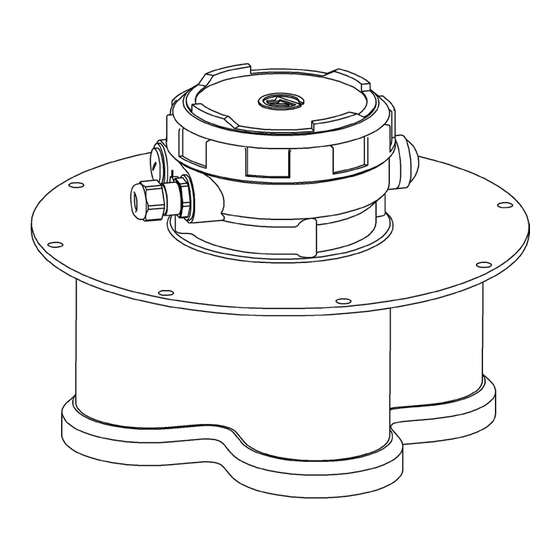
Page 8: Product Design
3.2 Product design Fig. 3.1. Appearance and location of key ULM-3D-5 components Fig. 3.2. Appearance and location of key ULM-3D-1 components 1 – aerial unit housing; 2 – mounting flange; 3 – cable gland or cable gland plug; 4 – electronic module housing; 5 –... -
Page 9: Product Identification
3.3 Product identification The device is identified in one of the possible ways: - as per the data specified on the device nameplate; - as per the attached product data sheet; - upon request to the manufacturer with the indication of level transmitter serial numbers. - Page 10 Fig. 3.4. ULM-3D-5 level transmitter on the tank Radar level transmitter aerial system emits a radio signal with a frequency of about 125 GHz and receives an echo signal reflected from the product surface. The elec- tronic unit processes the echo signal by means of a software and hardware complex and converts it into a corresponding output signal that carries information about the measured value.
- Page 11 riod (solid line in Fig.3.5). This signal (let's call it direct) is emitted by the level transmitter aerial in the direction of product surface. After the delay time Td, the signal reflected from the surface (the dotted line in Fig. 3.5) returns to the aerial Td –...
-
Page 12: Ulm-3D-5 Operation Specifics
Fig. 3.7. ULM-3D-1 level transmitter on the tank. Уровень (U) Level (U) Расстояние (L) Distance (L) Высота установки (H) Installation height (H) ULM-3D-1 level transmitter has one measuring channel, which is always oriented strictly along the vertical axis of level transmitter. 3.5 ULM-3D-3.5 operation specifics The measuring channels of ULM-3D-5 level transmitter work in turn. - Page 13 Fig. 3.8. Numbering of transmitter channels The measuring beam of each channel is oriented to a specific area of the product surface in the storage facility. Channel number 1 (central) is always oriented strictly along the vertical axis of the level transmitter. Other channels are oriented based on the specific application, see cl.
-
Page 14: Acceptance, Packaging, Transportation, And Storage Rules
Fig. 3.9. The direction of the measuring beams of level transmitter channels relative to the vertical axis of the level transmitter. 3.6 Acceptance, packaging, transportation, and storage rules During the acceptance of equipment, compliance with the following requirements is determined: - the completeness of level transmitter corresponds to the one specified in the data sheet;... -
Page 15: Installation
When kept in warehouses at railway stations, the level transmitter shall not be ex- posed to precipitation. The level transmitter shall be transported only in a package in covered railway cars, containers, and covered vehicles in accordance with storage conditions 5 as per GOST 15150-69, as per the rules of cargo transportation of the relevant transport ministries. - Page 16 Fig. 4.1. Device installation on the tank - do not install the device in such a way that the flow of product filling the vessel falls within the range of beam, the best location for the device is away from the loading site;...
- Page 17 - orient the level transmitter towards the lowest vessel point to ensure level mea- surement over the entire vessel depth; - in hot climates, use a visor or canopy to protect the device from direct sunlight; Fig. 4.3. Installation of device with a visor - the temperature at the location of level transmitter installation shall not exceed +50 °C;...
- Page 18 Fig. 4.4. Device installation - if the tank walls are not smooth (for example, corrugated metal, welds, structures), the distance from the wall shall be as far as possible. NOTE If the device is used on tanks made of non-conductive material (for example, plas- tic), it should be taken into account that structures outside the tank may fall into the measuring beam.
-
Page 19: Position For Installation
Fig. 4.5. Device installation. Tank made of non-conductive material. 4.2 Position for installation The best location and orientation of level transmitters in the space depends on the dimensions and structure of the tank, the number and location of product filling and unloading points. -
Page 20: Ulm-3D-5
8. Specify all existing discharge points of the tank. Provide drawings or sketches with dimensions. 4.3 Requirements for the installation on mounting nozzle for ULM-3D-5 min 305 mm Fig. 4.7. Device installation on the mounting nozzle Internal nozzle diameter D shall be 305 mm min. The permissible nozzle axis devia- tion from the vertical is 1°. -
Page 21: Measurement Beam Coverage
Nozzle height is measured along its inner surface from the flange to the lower edge of the hole. The maximum permissible nozzle height depends on its diameter. The larger the diameter, the higher the permissible nozzle. Using a nozzle exceeding recommended size may cause spurious re-reflections and hinder the measurement process. -
Page 22: Installation Examples For Ulm-3D-5
Fig. 4.9. Blind spot of the device Антенна датчика Sensor aerial Мертвая зона Blind spot Измерения невозможны Measurements are impossible Нестабильные измерения Unstable measurements Стабильные измерения с пониженной Stable low-accuracy measurements точностью Стабильные измерения с паспортной Stable rated accuracy measurements точностью... -
Page 23: Installation Examples For Ulm-3D-1
Fig. 4.11. Installation in the open storage facility 4.8 Installation examples for ULM-3D-1 Fig. 4.13, items A and B show examples of level transmitter installation in accor- dance with the requirements of this manual. Fig. 4.13 option A shows the installa- tion of level transmitter on the tank flange without a nozzle, option B shows instal- lation with a nozzle. - Page 24 Fig. 4.13. Installation examples RE_ULM3DX_18_02_20...
-
Page 25: Electrical Connection
5. ELECTRICAL CONNECTION 5.1 General instructions WARNING All connections shall be made when the voltage is off. Electrical connection shall be performed by qualified personnel who have a permit for this type of work. Two cable glands with self-sealing NPT threads may be installed in the level trans- mitter. -
Page 26: Shielding And Earthing
NOTE To protect the device from moisture, bent down the connection cable in the imme- diate vicinity of the cable gland to drain moisture from rain or condensate. 5.3 Shielding and earthing When using a shielded cable, connect the cable shield to the ground potential on one side. -
Page 27: Pin Assignment. Connection
5.4 Pin assignment. Connection. Fig. 5.2 ULM-3D-5. Pin assignment. Connection. Option 1. Адрес датчика Sensor address Резервная программа Back-up program 1 – Connecting to a PC; 2 – RS-485/USB converter; 3 – RS-485 line shield, connection to the "ground" on the side of converter; 4 –... - Page 28 Fig. 5.3 ULM-3D-5. Pin assignment. Connection. Option 2. Адрес датчика Sensor address Резервн. прогр. Back-up program Вкл. Выкл. 1 – Connecting to a PC; 2 – RS-485/USB converter; 3 – RS-485 line shield, connection to the "ground" on the side of converter; 4 –...
- Page 29 13 – Switch, matching load of RS-485 line R =120 Ohm; RE_ULM3DX_18_02_20...
-
Page 30: Power Supply
Fig. 5.4 ULM-3D-1. Pin assignment. Connection. Адрес датчика Sensor address Резервн. прогр. Back-up program Вкл. Выкл. Экран Shield Реле 1 Relay switch 1 Реле 2 Relay switch 2 1 – Connecting to a PC; 2 – RS-485/USB converter; 3, 6, 15 – Connecting the shields interface lines; 4 –... - Page 31 9 – Relay display unit, example of light alarm structure; 10 – microSD slot; 11 – Switch, matching load of RS-485 line R =120 Ohm; 12 – Modbus address switch; 13 – "Backup program" switch, return to factory settings; 14 – Switch for selecting the interface in use. 5.5 Power supply Use a stabilized DC power supply with an output voltage of (24..36) V.
-
Page 32: How To Connect The Device
Fig. 5.6 Diagram of level transmitter connection to the power source using a ter- minal box. Источник питания Power supply Магистральный кабель Trunk cable Клеммная коробка Terminal box 5.6 How to connect the device WARNING - strictly comply with the company's safety regulations; - perform all works with deactivated voltage;... - Page 33 1. Install the required number of cable glands in the device housing. When us- ing two cable glands, remove the plug with a 6 mm screwdriver and install the second cable gland in its place. 2. Remove the process plug from the cable gland installed at the factory. Fig.
-
Page 34: Level Transmitter Address Setup
Fig. 5.7 Connecting the level transmitter 7. Pull the wires slightly to make sure they are securely fixed in the terminal box terminals. 8. Adjust the cable length required for connection to the terminals and tighten the cable gland nut firmly. O-ring shall completely cover the cable. 9. -
Page 35: Initial Setup And Commissioning
6. INITIAL SETUP AND COMMISSIONING The device can be configured as follows before commissioning: 1) using a PC with RS-485 interface (Modbus RTU exchange protocol, see "Ex- change protocol for ULM sensors" for more details) and the ulmcfg configu- ration utility; 2) using a PC using NRT interface (under development);... - Page 36 6.2 PC connection via RS-6.2 The digital interface provides the user with access to the level transmitter readings and allows the user to configure and diagnose the level transmitter. The digital in- terface of level transmitter is implemented as a two-wire, serial RS-485 line. Mod- bus RTU data exchange protocol.
- Page 37 ATTENTION After connecting the interface converter to USB, install the device driver, if neces- sary. Right-click "My Computer" shortcut and select "Properties" from the context menu. In "System Properties" window that opens, in "Hardware" tab, click "Device Manager" button (the procedure for Win XP). In the hardware list, open "COM and LPT Ports"...
-
Page 38: Setting Key Parameters Of Level Transmitter Using Pc Via Rs- 485
Fig. 6.5 "Star" method of laying RS-485 line The low transmission rate of 9,600 bps used in the level transmitter ensures good noise immunity of the communication line and allows using various options for lay- ing cables, including "star" method, Fig. 6.5. The user chooses the appropriate op- tion for the convenience of laying cables and minimizing their length. -
Page 39: Troubleshooting
7. TROUBLESHOOTING The personnel responsible for the operation of level transmitter shall take steps to correct any arising problems. Do not use a faulty level transmitter. The sources of the failure of level transmitter-based measuring system can include: - level transmitter itself; - receiving device that displays information;... - Page 40 Failure Cause Troubleshooting method 4-20mA signal One or more monitored pa- Connect to the level transmitter us- corresponds to rameters of the level trans- ing a PC or a console. Check the mitter are outside tolerance: match of alarm value and its mask alarm values (cl.
- Page 41 Failure Cause Troubleshooting method - a small amplitude of re- Make spectrum recordings (see cl. flected signal – application 7.3.), send it to the technical sup- on products with low dielec- port. Follow further recommenda- tric conductivity, applica- tions. tion on bulk products, elec- tronic unit failure - signal loss - sudden Provided for reference, when a sta-...
- Page 42 Failure Cause Troubleshooting method RS-485 The required driver is not Check the operation of converter in connection installed or the initial set- the PC operating system (Device the presence of tings of USB/RS-485 con- Manager), make required settings 4-20 mA sig- verter are incorrect for the converter.
-
Page 43: The Structure Of Volume Measurement System
SCADA system located on a remote computer, install a remote version of Limaco OPC server on this computer and connect the SCADA system to this server in accordance with the connection standards via the OPC-interface. In this case the... - Page 44 Figure 8.1. The structure of volume measurement system. Удаленный ПК Remote PC Удаленный Remote Главный ПК Host PC Главный Host 3D Профиль 3D Profile Объем Volume Средний уровень Average level Минимальный уровень Minimum level Максимальный уровень Maximum level Отдельные уровни Separate levels RE_ULM3DX_18_02_20...
-
Page 45: Brief Description Of The Initial Master Software Setup
9.2. Multi Beam Radar Surface Plotter. 9.2.1. Before starting the configuration of this software, make sure that Limaco OPC server is correctly configured and running. 9.2.2. If this software is running on a remote (relative to the server) computer, find the line <endpoint address=... - Page 46 9.2.3. Then enter the key settings in the Multi Beam Radar Surface Plotter software. To do this, click settings button. 9.2.4. If this instance of the software is the master one, select "Write calculated data to sensor". You can enable several Multi Beam Radar Surface Plotter programs si- multaneously on the host and remote computers.
- Page 47 9.5. Remote connection of SCADA system. To enable connection to SCADA volume measurement system installed on a remote computer, first install Limaco OPC Server software on this computer. Configure it as a remote server. To do this, make changes manually to limacopc.cfg file generated during the instal- lation.
-
Page 48: Maintenance
10. MAINTENANCE The level transmitter does not require special maintenance. Depending on the oper- ating conditions, only periodic cleaning of the aerial shield surface may be required. When cleaning the level transmitter, do not use agents that can have an aggressive effect on the materials of housing, seals, plugs, and cable glands. -
Page 49: Repair
In case of return of the equipment to the manufacturer for repair, fill out a special form "Repair Application" posted on the website www.limaco.ru Procedure for sending the device for repair: - fill out the "Repair Application” form;... -
Page 50: Appendices
13. APPENDICES 13.1 Technical specifications Name Description General information Housing material Aluminum casting alloy, anodized, powder coating Sealing material between the housing Rubber compound and the cover Aerial shield material Polyethylene, fluoroplastic Bluetooth module plug material Fluoroplastic Cable gland material Nickel-plated brass Weight, kg, max ULM-3D-5... - Page 51 Name Description Device performance data Absolute level measurement error (on a ±5 mm max flat surface*) Range of measurement 0.6…40 m Low-accuracy measurement range 0.3…0.6 m Operation concept Radar level measurement device imple- menting linear frequency modulation (FMCW) Operating frequency 125±5 GHz Output power of each channel 8 MW max...
- Page 52 1 x plug М20х1.5 Option 2: 2 x cable glands M20x1.5 (round cable Ø 7...12 mm) Screw terminals for electrical connection 2.5 m (AWG 14) max of wires of Permits and certificates You can download this documents from the website www.limaco.ru RE_ULM3DX_18_02_20...
-
Page 53: Level Transmitter Connection To The Mounting Flange And Over- All Dimensions Of Ulm-3D-5
13.2 Level transmitter connection to the mount flange and overall dimensions of ULM-3D-5 RE_ULM3DX_18_02_20... - Page 54 13.3 Level transmitter connection to the mount flange and overall dimensions of ULM-3D-1 4 отв. М6х8-12 4 holes М6х8-12 Mounting dimensions of ULM-3D-1 level transmitter without a mounting flange Винт М6х10 DIN 912 (4 шт.) Screw М6х10 DIN 912 (4 pcs.) Connecting ULM-3D-1 level transmitter to a mounting flange RE_ULM3DX_18_02_20...
- Page 55 Installation of ULM-3D-1 level transmitter on a nozzle RE_ULM3DX_18_02_20...
- Page 56 13.4 Handling of cable gland Cable gland design Зажимная гайка Clamp nut Обжимная гильза Clamping sleeve Кольцо Ring Корпус Housing Профильное уплотнение Cross-sectional sealing IP rating: IP 68 - 10 bar / IP 69K within the specified cable diameter ranges and only with an addi- tional round O-ring External thread: M 20 x 1.5...
Need help?
Do you have a question about the ULM-3D Series and is the answer not in the manual?
Questions and answers