Table of Contents
Advertisement
Quick Links
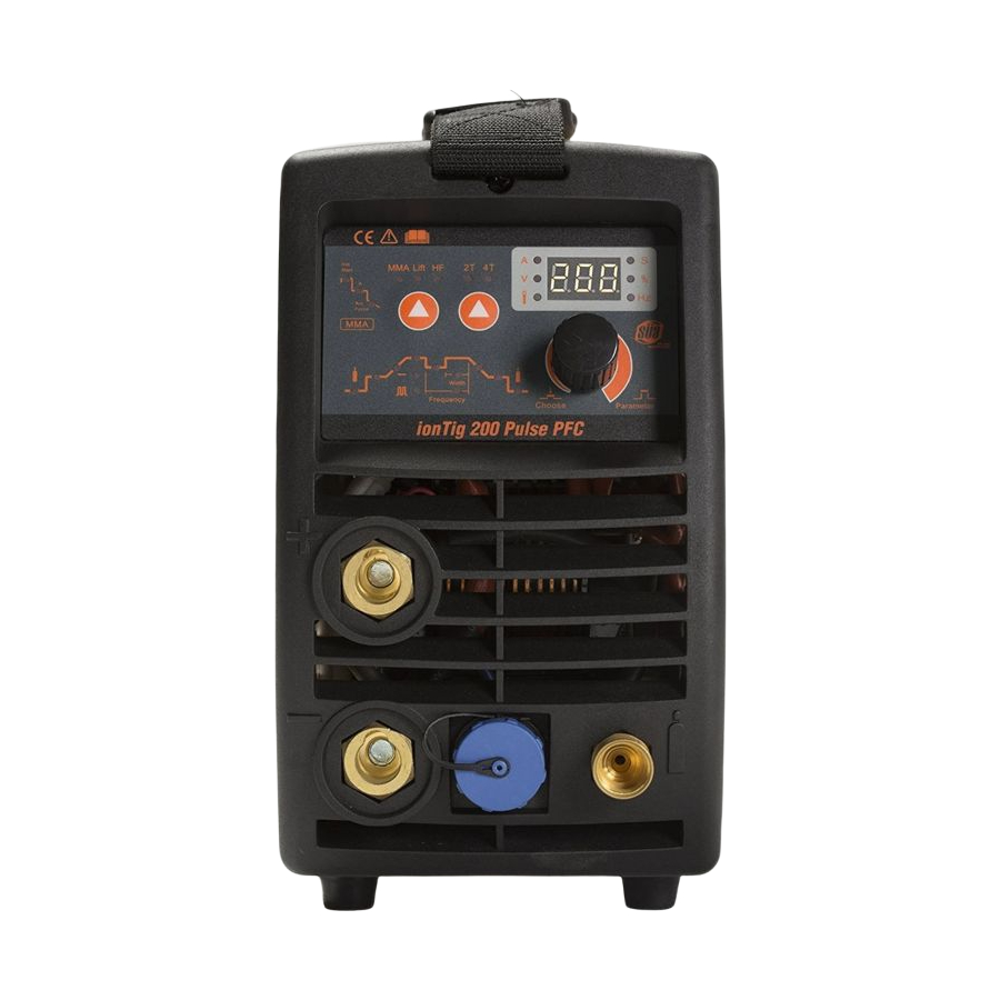
ionTig 200 Pulse PFC
ionTig 200 Pulse PFC
INVERTER - DC PULSED TIG WELDER
OPERATION MANUAL
IMPORTANT: Read this Owner's Manual Completely before attempting to use this
equipment. Save this manual and keep it handy for quick reference. Pay particular
attention to the safety instructions we have provided for your protection. Contact your
distributor if you do not fully understand this manual.
Copyright © Mundaka Welding & Gases, Inc.
Advertisement
Table of Contents
Troubleshooting

Related Manuals for Sua ionTig 200 Pulse PFC


Summary of Contents for Sua ionTig 200 Pulse PFC
- Page 1 200 Pulse PFC ionTig 200 Pulse PFC INVERTER - DC PULSED TIG WELDER OPERATION MANUAL IMPORTANT: Read this Owner’s Manual Completely before attempting to use this equipment. Save this manual and keep it handy for quick reference. Pay particular attention to the safety instructions we have provided for your protection.
-
Page 2: Table Of Contents
200 Pulse PFC CONTENT SAFETY ............................3 1.1 Signal Explanation..........................3 1.2 The Knowledge of Electric and Magnetic Fields ................6 Overview ............................7 2.1 Brief Introduction..........................7 2.3 Volt-Ampere Characteristic ......................10 Installation and Adjustment ......................11 3.1 Parameters ............................11 3.2 Duty cycle and Over-heat....................... -
Page 3: Safety
200 Pulse PFC 1. SAFETY 1.1 Signal Explanation Welding may damage your body or others, so please take protection measure in operation. Only ones who are trained professionally can install, debug, operate, maintain and repair the equipment. - Page 4 200 Pulse PFC FUMES AND GASES CAN BE DANGEROUS Welding may produce fumes and gases hazardous to health. Avoid breathing these fumes and gases. When welding, keep your head out of the fume. Use enough ventilation and/or exhaust at the arc to keep fumes and gases away from the breathing zone.
- Page 5 200 Pulse PFC ELECTRIC SHOCK CAN KILL. Never touch electrical parts. Wear dry, hole-free gloves and clothes to insulate yourself. Insulate yourself from work and ground using dry insulation. Make certain the insulation is large enough to cover your full area of physical contact with work and ground.
-
Page 6: The Knowledge Of Electric And Magnetic Fields
200 Pulse PFC Where compressed gases are to be used at the job site, special precautions should be used to prevent hazardous situation. When not welding, make certain no part of the electrode circuit is touching the work or ground. Accidental contact can cause overheating and create a fire hazard. -
Page 7: Overview
Thus, it is characterized with portable, small size, light weight, low consumption and etc. The parameters of ionTig 200 Pulse PFC on the front panel all can be adjusted continuously and sleeplessly, such as start current, crater arc current, welding current, base current, duty ratio, upslope time, downslope time, pre-gas, post-gas, pulse frequency, AC frequency, balance, hot start, arc force and arc length etc. - Page 8 200 Pulse PFC ionTig 200 Pulse PFC Characteristics: DC Pulsed TIG and MMA, adopt IGBT and advanced PWM technology High performance MCU, Digital control, Digital display Preset all parameters with hold process HF/Lift TIG, current down slope and up slope, gas post-flow, Pulse Frequency ...
- Page 9 200 Pulse PFC MMA——Manual Metal Arc welding PWM——Pulse-Width Modulation IGBT——Insulation Gate Bipolar Transistor TIG——Tungsten Insert Gas welding 2.2 Working Principle The working principle of TP- series welding machines is shown as the following figure. Single phase work frequency AC 220V (50 Hz) is rectified into DC (about 380V), then is converted to medium...
-
Page 10: Volt-Ampere Characteristic
200 Pulse PFC 2.3 Volt-Ampere Characteristic ionTig 200 Pulse PFC welding machine has an excellent volt-ampere characteristic, whose graph is shown as the following figure. The relation between the conventional rated loading voltage U2 and the conventional welding current I2 is as follows: When I2≤600A,U2=10+0.04I2(V);... -
Page 11: Installation And Adjustment
200 Pulse PFC 3. Installation and Adjustment 3.1 Parameters Models TIG 200 DC PULSE PFC Parameters Input power Single phase,110V,50/60Hz Single phase,220V, 50/60Hz 24.5 Rated input current(A) Rated input power(KW) Power factor 0.99 0.99 5~120 5~200 Welding current range(A)... -
Page 12: Duty Cycle And Over-Heat
200 Pulse PFC 3.2 Duty cycle and Over-heat The letter “X” stands for duty cycle, which is defined as the proportion of the time that a machine can work continuously within a certain time (10 minutes). The rated duty cycle means the proportion of the time that a machine can work continuously within 10 minutes when it outputs the rated welding current. -
Page 13: Power Supply Input Connection
3.4 Power supply input connection ionTig 200 Pulse PFC welding machines’ power supply connects to 220V. When the power supply voltage is over the safe work voltage, there are over voltage and under voltage protection inside the welder, the alarm light will on, at the same time, the current output will be cut off. -
Page 14: Assembling The Equipment (Tig)
(short/long) , please enquire us by mail or phone according to the accessory codes. When ionTig 200 Pulse PFC welding machines are operated in HF ignition method, the ignition spark can cause interferences in equipment near the welding machine. Be sure to take specially safety precautions or shielding measures. -
Page 15: Control Panel
200 Pulse PFC (1) Positive output: The welder’s positive polarity output. (2) Negative output: The welder’s negative polarity output. (3) Aero socket: Is connected to torch switch control wire.(It has 14 leads and lead 8 - lead 9 are connected to torch switch control wire). - Page 16 200 Pulse PFC -shown on the display during welding. The illustration below shows an overview of the main settings needed for day-to-day working, using the TIG 200 DC PULSE control panel as an example. You will find a detailed description of these settings in the following section.
- Page 17 200 Pulse PFC Starting current (only with 4T) Unit Setting range 5—100%of main current Iw Factory setting Upslope time Unit Setting range 0.0—2.0 Factory setting Welding current Unit TIG 200 DC PULSE 5—200; TIG 200 DC PULSE PFC 5—200;...
- Page 18 200 Pulse PFC Unit Setting range 0—10 Factory setting Crater arc current (only with 4T) Unit 5—100% of main current Iw ; Setting range Factory setting Gas post-flow time Unit Setting range 0.0—10.0 Factory setting (3) Rod electrode (MMA) welding parameter...
-
Page 19: Argon Arc Welding Operation
200 Pulse PFC NOTE: Only the Iw of TIG or the welding current of MMA can be adjust when welding. 4.3 Argon Arc Welding Operation 4.3.1 TIG welding (4T operation) The start current and crater current can be pre-set. This function can compensate the possible crater that appears at the beginning and end of the welding. -
Page 20: Tig Welding (2T Operation)
200 Pulse PFC t4: Repress down the gun switch, the output current slopes down to crater current; if the output pulse function is turned on, the slope down current is pulsed; t4~t5: Down slope time, adjustment rang of down slope time: 0~10.0S;... - Page 21 200 Pulse PFC t4~t5: Post flow time, adjustment range of post flow time: 0.0~10.0S; t5: Electromagnetic valve is closed and stop argon flowing. Welding is finished. Short circuit protect function: (1) TIG /LIFT:If the tungsten electrode touches the workpiece when welding, the current will drop to 5A, which can reduce the tungsten spoilage,prolong the using life of the tungsten electrode and...
-
Page 22: Welding Parameters
200 Pulse PFC electrode during the ignition. 4.4 Welding Parameters 4.4.1 Joint forms in TIG/MMA lap joint coner joint T joint butt joint 4.4.2 The explanation of welding quality The relation of welding area color & protect effect of stainless steel... -
Page 23: Tig Parameters Matching
200 Pulse PFC 4.4.3 TIG Parameters Matching The corresponding relationship between gas nozzle diameter and electrode diameter Gas nozzle diameter/mm Electrode diameter/mm 1.6 or 2.4 11.1 Notice: the above parameters originate from《Welding Dictionary》P142, Volume 1 of Edition 2. Gas nozzle and the shield gas flow rate... - Page 24 200 Pulse PFC TIG of stainless steel (single run welding) Workpiece tungsten Argon gas welding Welding welding wire thickness Joint form electrode flow rate/ current speed/ diameter/mm diameter/mm L·min (DCEP) cm·min Butt joint 20~50 Butt joint 50~80 Butt joint 65~105...
-
Page 25: Operation Environment
200 Pulse PFC 110~ 8~10 14~16 12~14 5~6 120~ 8~10 14~16 12~14 5~6 Notice: the above parameters originate from《Welding Dictionary》P167, Volume 1 of Edition 2. 4.5 Operation Environment ● Height above sea level is below 1000m. ● Operation temperature range:-10 C~+40... -
Page 26: Maintenance & Troubleshooting
200 Pulse PFC ● Turn off the engine when the operation finished to economize energy source. ● When power switch shuts off protectively because of failure. Don’t restart it until problem is resolved. Otherwise, the range of problem will be extended. -
Page 27: Troubleshooting
200 Pulse PFC Observe that whether the display value of LED is intact. If the display number is not intact, please replace the damaged LED. If it still doesn’t work, please maintain or replace the display PCB. Observe that whether the min/max value on LED accords with the set value. If there is any difference and it has affected the normal welding craft, please adjust it. - Page 28 200 Pulse PFC Maintenance course must be operated carefully. If any wire becomes flexible or is misplaced, it maybe potential danger to user! Only professional maintenance personal who is authorized by us could overhaul the machine! Guarantee to shut off the arc welding machine’s power before turn on the outline of the equipment! ...
- Page 29 200 Pulse PFC Troubles Reasons Solution The HF igniting board does not work. Repair or change Pr8 There is not spark on the The distance between the discharger Adjust this distance (about HF igniting is too short. 0.7mm). board.
-
Page 30: Electrical Principle Drawing
200 Pulse PFC 5.3 Electrical principle drawing Copyright © Mundaka Welding & Gases, Inc.
Need help?
Do you have a question about the ionTig 200 Pulse PFC and is the answer not in the manual?
Questions and answers