Table of Contents
Advertisement
Quick Links
Asian Electron Co., Ltd.
Importør
Extron AS
Nedre Rælingsvei 261
2008 Fjerdingby
Tlf. 63 83 33 90, Mobil 90032394
www.extron.no, e-post: post@extron.no
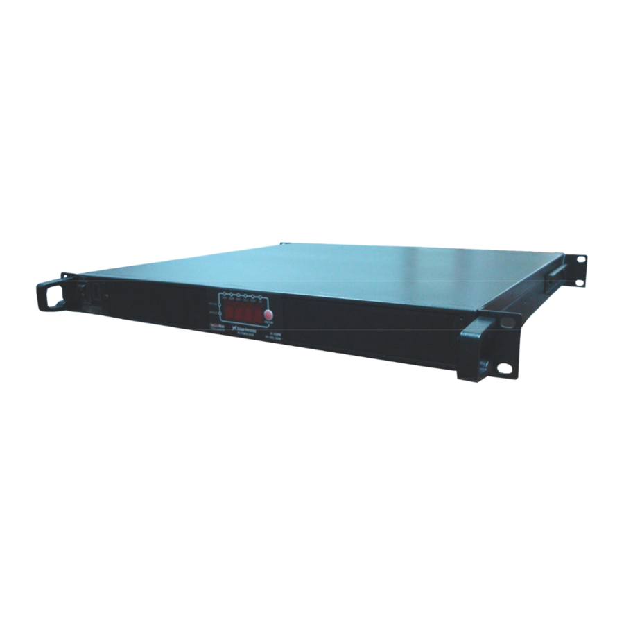
1U 19"/23"/ Open Rack Inverter
1U1KVA & 1U2KVA Series
Pure Sine Wave Inverter
YK-PSW241KVAE; YK-PSW242KVAE
YK-PSW481KVAE; YK-PSW482KVAE
Instruction Manual
Advertisement
Table of Contents

Related Manuals for Asian Electron Extron AS

Summary of Contents for Asian Electron Extron AS
- Page 1 Asian Electron Co., Ltd. Importør Extron AS Nedre Rælingsvei 261 2008 Fjerdingby Tlf. 63 83 33 90, Mobil 90032394 www.extron.no, e-post: post@extron.no 1U 19”/23”/ Open Rack Inverter 1U1KVA & 1U2KVA Series Pure Sine Wave Inverter YK-PSW241KVAE; YK-PSW242KVAE YK-PSW481KVAE; YK-PSW482KVAE Instruction Manual...
-
Page 2: Table Of Contents
List of Contents 1. Features Application Electrical performance Mechanical drawings 2. Introduction Front panel operations Rear panel operations Installation Quick hook – up and testing AC safety grounding Making DC wiring connections Inverter operation Cooling fan working code 3. Maintenance 4. -
Page 3: Features
1. Features R Load Pure sine wave output (THD < 3%) By pass function Output frequency: 50 / 60Hz switch RS-232 interface / Wire connection to PC Wired Remote control (optional) Loading controlled cooling fan Advanced microprocessor Protection: Input Undervoltage Input Overvoltage Overload Short circuit... -
Page 4: Electrical Performance
1-2 Electrical Performance 1U1KVA Model Specification YK-PSW121KVAE YK-PSW241KVAE YK-PSW481KVAE Item Continuous Output 850W (1KVA) Power Surge Rating 900W/1Mins , 950W/3Sec , 1000W/1Sec Input Voltage Frequency 50/60Hz ± 0.05% ( Switch Selectable) Peak Output Current Efficiency (full load) No Load Current Draw 0.7A 0.35A 0.25A... - Page 5 1U2KVA Specification Model YK-PSW122KVAE YK-PSW242KVAE YK-PSW482KVAE Item Continuous Output 1600W 1700W 1700W Power Surge Rating 1870W/1Min, 2040W/20Sec Input Voltage Frequency 50/60Hz ± 0.05% ( Switch Selectable) Peak Output Current Efficiency (full load) No Load Current Draw 1.47A 0.8A 0.47A Output Waveform R Load Pure Sine Wave <3% THD Output Voltage 200/220/230/240V(Switch Selectable) RMS±3%...
-
Page 6: Mechanical Drawings
1-3 Mechanical Drawings... -
Page 7: Introduction
2. Introduction: The power inverter series are the member of the most advanced line of mobile AC power systems available. To get the most out of the power inverter, it must be installed and used properly. Please read the instructions in this manual before installing and using this model. 2-1 Front Panel Operation: 2-1-1 Front view: 2-1-2 ON / OFF switch:... -
Page 8: Rear Panel Operations
2-2 Rear Panel Operation: 2-2-1 Ventilation openings: Do not obstruct, allow at least 3 inch for air flow. 2-2-2 Battery terminals: Connect to 12V / 24V / 48V battery or other 12V / 24V / 48V power Source. 【+】is positive,【-】is negative. Reverse polarity connection will blow internal fuse and may damage inverter permanently. -
Page 9: Installation
WARNING! Any damages caused by using incorrect RS232 cable will be outside of our warranty scope. If you are not sure which one is correct RS232 cable, please purchase the correct RS232 cable from us directly. 2-2-4 Connect chassis ground terminal to earth or to vehicle chassis using # 8 AWG wire. WARNING! Operation of the inverter without a proper ground, connection may result in an electrical safety hazard. -
Page 10: Quick Hook - Up And Testing
2-3-3 Safe – Do not install in a battery compartment or other areas where flammable fumes may exist, such as fuel storage areas or engine compartments. 2-3-4 Ventilated – Allow at least one inch of clearance around the inverter for air flow. Ensure the ventilation openings on the rear and bottom of the unit are not obstructed. -
Page 11: Ac Safety Grounding
CAUTION! Reverse polarity connection will blow a fuse in inverter and may permanently damage the inverter. Damage caused by reversing polarity connection is not covered by our warranty. 2-4-4 Connect the cable from the negative terminal of the inverter to the negative terminal of the power source. -
Page 12: Making Dc Wiring Connections
CAUTION: This equipment is designed to permit the connection of the earthed conductor of the DC supply circuit to the earthing conductor at the equipment. If this connection is made, all of the following conditions must be met: This equipment shall be connected to directly to the DC supply system earthing electrode conductor or to a bonding jumper from an earthing terminal bar or bus to which the DC supply system earthing electrode conductor is connected. -
Page 13: Inverter Operation
Model No Wire AWG Inline Fuse YK-PSW121KVAE 150A YK-PSW241KVAE YK-PSW481KVAE Model No Wire AWG Inline Fuse YK-PSW122KVAE #2/0 250A YK-PSW242KVAE #1/0 125A YK-PSW482KVAE Also, use only high quality copper wiring and keep cable length short from 3-6 feet. 2-7 Inverter Operation: To operate the power inverter, turn it on using the ON/OFF switch on the front panel. - Page 14 2-7-4 Output Watts Indicator LED displays light on Watts as show as output Watts value 2-7-5 Input DC Voltage Indicator LED displays light on VDC as show as input DC voltage value 2-7-6 Temperature Indicator LED displays light on TEMP as show as internal operating temperature value 2-7-7 Output Frequency AC Indicator LED displays light on Hz as show as output frequency value Please have the accuracy of 6 functions of display, as below:...
-
Page 15: Cooling Fan Working Code
2-7-11 Overload protection indicator: (OLP) The overload indicator indicates that the power inverter has shut itself down. When output voltage over continue power, then must return to operate manually. 2-8 Cooling fan working code: Cooling fan of inverter is through detecting output power and over temperature situation to work. When start to turn on the inverter and output power is under 300W, the cooling fan does not start running. -
Page 16: Troubleshooting Guide
4.Troubleshooting guide: WARNING! Do not open or disassemble the inverter. Attempting to service the unit yourself may result in a risk of electrical shock or fire. Problem and Symptom Possible Cause Solution Low output voltage Using average reading Use true RMS reading meter (220V: 190-210VAC) voltmeter and cable. -
Page 17: General Safety Precautions
6. Important Safety Instructions WARNING! Before you install and use your inverter, be to read and save these safety instructions. 6-1 General Safety Precautions 6-1-1 Do not expose the Inverter to rain, snow, spray, bilge or dust. To reduce risk of hazard, do not cover or obstruct the ventilation openings. -
Page 18: Appendices A
S2 S3 (BAUD RATE ) – 2400 / 4800 / 9600 / 19200 S4 S5 (VOLTAGE OUTPUT ) – 200VAC/220VAC/230VAC/240VAC When you set up S1~S5, please reset the inverter and let update data through CPU. RE-MARK: The user manual is subject to change without notice. Produsent: Asian Electron Co., Ltd. TAIWAN...
Need help?
Do you have a question about the Extron AS and is the answer not in the manual?
Questions and answers