Table of Contents
Advertisement
Quick Links
Advertisement
Table of Contents

Related Manuals for DATREND Systems AMPS-1

Summary of Contents for DATREND Systems AMPS-1
- Page 1 AMPS-1 Ad v an c e d Mo d u lar Patie n t Sim u lato r Operating Manual...
- Page 3 AMPS-1 Advanced Modular Patient Simulator Operating Manual © 2008-2021 Datrend Systems Inc. Unit 130 - 4020 Viking Way Richmond, BC • CANADA • V6V 2L4 Tel: 800.667.6557 (North America Only) or 604.291.7747 • Fax 604.294.2355 e-mail: customerservice@datrend.com...
- Page 5 Channels Copyright Datrend Systems Inc. (“DSI”) agrees to a limited copyright release that allows you to reproduce manuals and other printed materials for use in service training programs and other technical publications. If you would like other reproductions or distributions, submit a written request to Datrend Systems Inc.
- Page 6 Warranty and Product Support Datrend Systems Inc. ("DSI") warrants this instrument to be free from defects in materials and workmanship under normal use and service for one (1) year from the date of original purchase. This warranty will be automatically extended on a yearly basis, to a maximum of five (5) years from the date of original purchase, provided that calibration is performed on an annual basis by a Datrend Authorized Service Center.
- Page 7 In the event that the seal must be broken to gain internal access to the instrument (e.g., in the case of a customer-installed firmware upgrade), you must first contact Datrend Systems. You will be required to provide us with the serial number for your instrument as well as a valid reason for breaking the Quality Seal. You should break this seal only after you have received factory authorization.
-
Page 9: Table Of Contents
2.8 Navigating AMPS-1 Menus........ - Page 10 13.2 Connecting AMPS-1 to a PC........
- Page 11 AMPS-1 OPERATING MANUAL 15 Enabling Optional Features......... . . 75 15.1 Overview.
- Page 12 AMPS-1 OPERATING MANUAL Abbreviations, Definitions and Symbols The following abbreviations, terms and acronyms are used throughout this manual: degrees Celsius (centigrade) degrees Fahrenheit Automated External Defibrillator American Heart Association Arrhythmia An abnormal rhythm of the cardiac muscle; an abnormal pattern or rate of heart beats.
- Page 13 AMPS-1 OPERATING MANUAL Pacer A transvenous or implanted pacemaker Premature Atrial Contraction Premature Nodal Contraction Premature Ventricular Contraction QRS complex A specific segment of the electrocardiogram signal, comprising the Q, R and S waves, which corresponds to the heart systole.
- Page 14 AMPS-1 OPERATING MANUAL...
-
Page 15: Specifications
• RS-232 Serial Port: proprietary RJ-12 User Interface: AMPS-1 is controlled through 17 keys on the front panel keypad, allowing the user to easily access all functions of the simulator. As individual functions are activated, they remain active unless turned off, allowing numerous simulations to be enabled concurrently, with all appropriate signals synchronized. -
Page 16: Simulation Specifications
AMPS-1 OPERATING MANUAL Display: 20 character by 2 line alphanumeric LCD Dimensions and Weight: • 10 x 19 x 3 cm (4" x 7d" x 1¼") • 0.34 kg (12 oz) 1.2 Simulation Specifications ECG General: • Simulation Type: Full 12-Lead ECG with independent outputs for each signal lead, referenced to RL •... - Page 17 AMPS-1 OPERATING MANUAL Arrhythmia: GENERAL 1 • Asystole 1 • Trigeminy 1, PVC 1 • Asystole 2 • Trigeminy 2, PVC 2 • Asystole 3 • PAC • Bigeminy 1, PVC 1 • PNC • Bigeminy 2, PVC 2 • Multifocal PVC •...
- Page 18 AMPS-1 OPERATING MANUAL AED/Shock Advisory: • Ventricular Rhythm @ 90 BPM • Emergency 1 • Ventricular Rhythm @ 120 BPM • Emergency 2 • Ventricular Tachycardia @ 140 BPM • Elective Cardioversion • Ventricular Tachycardia @ 160 BPM • Defib NOW •...
- Page 19 • Pacer Pulse Polarity: Positive or negative Invasive Blood Pressure (OPTIONAL): • Channels: 2 or 4 functionally identical channels • Electrical Isolation: Isolates BP channels from other AMPS-1 connections (ECG, temperature, respiration) • Static Pressures: -10, -5, 0, 20, 40, 60, 80, 100, 120, 150, 160, 180, 200, 240, 320 and 400 mmHg •...
- Page 20 • Intrauterine Pressure: 0-25, 0-50 and 0-100 mmHg • Transducer Sensitivity: 5 µV/V/mmHg or 40 µV/V/mmHg Auto Presets: Ten user-defined simulation setups can be programmed and uploaded to AMPS-1 using the AMPSpc software (standard accessory, included). Specifications/Chapter 1 # Page 6...
-
Page 21: General Information
2.2 Features The compact and portable AMPS-1 measures just 10 x 19 x 3 cm (4" x 7d" x 1¼"), weighs less than 350 grams (12 ounces), and operates for approximately 20 hours continuous use when powered by a single 9 Volt alkaline battery. -
Page 22: Main Functions Of Amps-1
Details and specifications of each function are described in the chapters to follow. 2.4 Powering up AMPS-1 To power up, press the POWER button on the left side of AMPS-1. The Power-On screen (Figure 1), which shows the firmware version number, will appear briefly and then be replaced by the Selection screen (Figure 2). -
Page 23: Alpha And Numeric Modes
When a desired setting is shown on the LCD display, the ENTER button is pressed to activate the setting. In NUMERIC mode, code numbers can be input via the AMPS-1 keypad which will then activate corresponding simulation functions or settings. Code numbers used in NUMERIC mode are listed in Appendix A of this manual. - Page 24 BASE= 37°C Figure 9- POWER ON #7: CO defaults At power-up, AMPS-1 initially sets all blood pressure (BP) channels to ze ro p re s s u re , regardless of which dynamic BP waveforms may have been set as the power-on defaults. This allows the pressure channels of the monitor under test to be zeroed.
-
Page 25: Alpha Mode
AMPS-1 memory. 2.6.2 Numeric Mode After powering up AMPS-1, simulator operation will default to ALPHA mode. To switch to NUMERIC mode, press the SHIFT key. Referring to the table in the preceding section, and to the numeric codes listed in Appendix A, find the numeric code for the setting you wish to apply as a power-on default. -
Page 26: Ampspc
AMPSpc companion software, supplied on CD ROM as a standard accessory with AMPS-1, allows you to program the power-on default settings using drop-down boxes. Simply make the desired selections, connect AMPS-1 to your PC using the RS-232 serial cable provided, and upload to AMPS-1. -
Page 27: Connecting To Amps-1
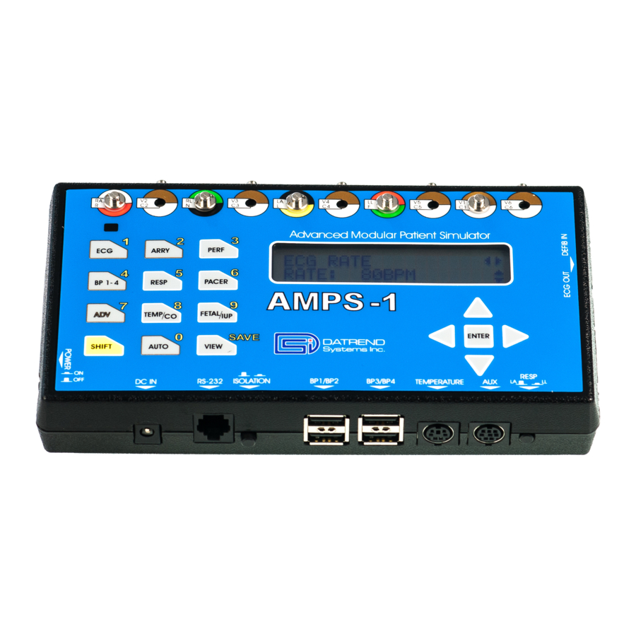
AMPS-1 OPERATING MANUAL 2.7 Connecting to AMPS-1 As shown in Figure 11, the top side of AMPS-1 features a full set of universal ECG snaps and jacks, enabling connection of any 3-, 5-, or 10-lead ECG device. AHA and IEC colour-coded rings surrounding each post and jack aid in connection of corresponding U.S. -
Page 28: Navigating Amps-1 Menus
ECG function are: Rate, Amplitude, Baseline and Artifact. LEFT ( ) and RIGHT ( ) arrow keys on the right side of AMPS-1, under the LCD, allow you to scroll through the available parameters. UP ( ) and DOWN ( ) arrow keys are used to modify the s e ttin g for the displayed parameter. -
Page 29: Ecg Normal Sinus Rhythm
(and the muscle activity they represent). This display indicates the overall rhythm of the heart, and weaknesses in different parts of the heart muscle. AMPS-1 simulates normal and irregular heartbeats with adjustable settings for heart rate, amplitude, and ST Segment elevation/depression. -
Page 30: Available Settings
AMPS-1 OPERATING MANUAL Figure 12 - QRS Complex 3.3 Available Settings Press ENTER after selecting a parameter to activate that setting. 3.3.1 Rates • 30, 40, 60, 80, 100, 120, 140, 160, 180, 200, 220, 240, 260, 280 and 300 BPM 3.3.2 Amplitudes (Lead II) -
Page 31: Ecg Function
AMPS-1 OPERATING MANUAL 3.4 ECG Function Parameters provided for the ECG function are: Rate; Amplitude; Baseline; and Artifact. Press the ECG(1) button to change the LCD display to that of Figure 13, the ECG Rate Menu. ECG RATE RATE: 30BPM... - Page 32 AMPS-1 OPERATING MANUAL Pressing the RIGHT ( ) arrow button will change the screen to that of Figure 15, the Baseline Impedance Menu. ECG BASELINE IMPEDANCE:1000 Ù Figure 15- ECG BASELINE IMPEDANCE Press the UP ( ) or DOWN( ) arrow button to scroll through the settings provided for the baseline impedance: 500, 1000, 1500 and 2000Ù.
-
Page 33: Ecg Advanced Function
AMPS-1 OPERATING MANUAL 3.5 ECG Advanced Function There are several additional parameters associated with the ECG simulation which may be used less frequently. These parameters (ECG ST, ECG AXIS and ECG NEONATAL) are available via the ADV(7) button. Pressing the ADV(7) button while viewing the ECG menu will change the screen to that of Figure 17, the ST Segment Menu. - Page 34 AMPS-1 OPERATING MANUAL Pressing the RIGHT ( ) arrow button will change the menu screen to that of Figure ECG NEONATAL NEONATAL: OFF Figure 19- ECG ADVANCED: NEONATAL Press the UP ( ) or DOWN( ) arrow button to toggle the NEONATAL simulation between OFF and ON.
-
Page 35: Arrhythmias
But if arrhythmias persist for some time, they may cause severe pain, unconsciousness, or death. AMPS-1 offers a wide range of arrhythmia simulations to test the function of patient monitors. AMPS-1 can also be used in training clinicians in arrhythmia recognition. - Page 36 AMPS-1 OPERATING MANUAL 4.2.5 Premature Ventricular Contraction, Type 1 (PVC1) • Left Ventricular Focus (LVF)* • Early LVF* • R-on-T LVF* • 6, 12, and 24 per minute • Pair* • Run of 5, run of 11 4.2.6 Premature Ventricular Contraction, Type 2 (PVC2) •...
- Page 37 AMPS-1 OPERATING MANUAL 4.2.15 Fibrillation • Coarse atrial fibrillation • Fine atrial fibrillation • Coarse ventricular fibrillation • Fine ventricular fibrillation 4.2.16 Paroxysmal Atrial Tachycardia • 160 BPM for 5 seconds and normal 80 BPM sinus rhythm for 12 seconds 4.2.17 Supraventricular Tachycardia...
-
Page 38: Arrhythmia Function
AMPS-1 OPERATING MANUAL 4.3 Arrhythmia Function The arrhythmia simulations of AMPS-1 have been grouped into eight categories: GEN1 (general #1); PVC1; PVC2; (conduction) BLOCK; FIBRILL (fibrillation), TACHY (tachycardia), GEN2 (general #2); and AED. Press the ARRY(2) button and the LCD display will change to that of Figure 20, the ARRHYTHMIA main menu. - Page 39 AMPS-1 OPERATING MANUAL ARRHYTHMIA: PVC2 PVC2 RVF* Figure 22- ARRHYTHMIA: "PVC2" Group Press the UP ( ) or DOWN( ) arrow button to scroll through the arrhythmia waveforms provided under PVC group #2: PVC2 RVF*, PVC2 EARLY RVF*, PVC2 RonT RVF*, PVC2 6/MIN, PVC2 12/MIN, PVC2 24/MIN, PVC2 PAIR*, PVC2 RUN 5*, and PVC2 RUN 11*.
- Page 40 AMPS-1 OPERATING MANUAL ARRHYTHMIA: TACHY PAROXYSMAL Figure 25- ARRHYTHMIA: "TACHY" Group Press the UP ( ) or DOWN( ) arrow button to scroll through the arrhythmia waveforms provided under the tachycardia group: PAROXYSMAL and SUPRAVENT. Pressing the RIGHT ( ) arrow button will change the menu screen to that of Figure...
-
Page 41: Defibrillator Training
AMPS-1 via the "DEFIB IN" jack. 4.4.2 External Trigger Specifications The trigger signal that may be applied to "DEFIB IN" of AMPS-1 is n o t a defibrillator discharge, but is simply a low-level pulse signal that represents a synchronization pulse from a defibrillator. -
Page 42: Defibrillator Discharge Simulation
(AFIB). For defibrillation to be effective, the "discharge" must be properly synchronized to the ECG R-wave. If a trigger pulse is detected by AMPS-1 and is within +/-100 milliseconds of the R-wave, defibrillation is successful and the ECG will then convert to a normal sinus rhythm. -
Page 43: Arrhythmia Advanced Function
AMPS-1 OPERATING MANUAL 4.5 Arrhythmia Advanced Function Pressing the ADV(7) button anytime while in ARRY mode will change the screen to that of Figure 28, the arrhythmia amplitude menu. ARRHYTHMIA:AMPL AMPL: 1mV Figure 28 - ARRHYTHMIA ADVANCED: AMPLITUDE Press the UP ( ) or DOWN( ) arrow button to scroll through the amplitude settings for the selected arrhythmia waveform: 0.1, 0.25, 0.5, 1, 2, 3, 4 and 5mV. - Page 44 AMPS-1 OPERATING MANUAL Arrhythmias/Chapter 4 # Page 30...
-
Page 45: Performance Waveforms
AMPS-1 OPERATING MANUAL 5 Performance Waveforms 5.1 Overview AMPS-1 offers a number of performance waveforms to evaluate linearity, frequency response, R-wave detection and other aspects of the performance of patient monitors and chart recorders. When Performance Waves are selected, all BP channels are set to a static pressure of zero mmHg, and the respiration rate is set to zero. -
Page 46: Ecg Performance Function
AMPS-1 OPERATING MANUAL 5.2.6 Performance Amplitude • Lead II, 0.05 to 5.50 mV in 0.05 mV steps • Applies to the currently-selected performance waveform 5.3 ECG Performance Function Parameters provided for the ECG performance function are: Square, Triangle and Pulse waveform;... - Page 47 AMPS-1 OPERATING MANUAL Press the UP ( ) or DOWN( ) arrow button to scroll through the pulse widths provided for the Haver-triangle waveform: 8, 12, 20, 40, 60, 80, 100, 120, 140, 160, 180 and 200 milliseconds. This waveform can be used to test R-wave detection performance of a patient monitor.
- Page 48 AMPS-1 OPERATING MANUAL Performance Waveforms/Chapter 5 # Page 34...
-
Page 49: Invasive Blood Pressure (Optional)
A dynamic blood pressure value is normally written with the systolic blood pressure first, followed by the diastolic blood pressure (for example 120/80). AMPS-1 offers the option of two or four electrically isolated BP channels and simulates static pressures, as well as dynamic BP waveforms that track arrhythmia and normal sinus ECG simulations. -
Page 50: Available Settings
In most cases, the ISOLATION button (located next to the RS-232 port on the bottom side of AMPS-1) should remain in the OFF (out) position. If there seems to be an interaction when ECG and BP signals of AMPS-1 are simultaneously connected to a monitor, press the ISOLATION button to the ON (in) position. -
Page 51: Blood Pressure Function (Optional)
Since all four channels have the same parameters and options, only BP1 will be described below. With AMPS-1 displaying the menu of Figure 34, press the UP ( ) or DOWN( ) arrow button to scroll through the static levels provided for the low pressure range: -10, -5, 0, 20, 40, 60, 80 and 100 mmHg. - Page 52 AMPS-1 OPERATING MANUAL Press the UP ( ) or DOWN( ) arrow button to scroll through the static levels provided for the high pressure range: 120, 150, 160, 180, 200, 240, 320 and 400 mmHg. Pressing the RIGHT ( ) arrow button will change the menu screen to that of Figure...
-
Page 53: Blood Pressure Advanced Function
AMPS-1 OPERATING MANUAL 6.4 Blood Pressure Advanced Function Parameters provided under "Advanced" BP are: Swan-Ganz; Sensitivity; and Default Sensitivity. Pressing the ADV button while viewing any of the blood pressure menu screens will change the display to that of Figure 38. Note that for the BP-ADV menu, changes made to settings will only affect the BP channel indicated at the top left corner of the LCD display, for example, BP1 as shown in Figure 38. - Page 54 AMPS-1 OPERATING MANUAL Press the UP ( ) or DOWN( ) arrow button to toggle the (power-on) default sensitivity between 5 and 40 µV/V/mmHg. Pressing the RIGHT ( ) arrow button will change the menu screen to that of Figure...
-
Page 55: Respiration
AMPS-1 OPERATING MANUAL 7 Respiration 7.1 Overview AMPS-1 sends the respiration signal to either the Left Arm (LA) or Left Leg (LL) ECG lead as selected by the RESP button located on the right of AMPS-1. 7.2 Available Settings Press ENTER after selecting a parameter to activate that setting. -
Page 56: Respiration Function
AMPS-1 OPERATING MANUAL 7.3 Respiration Function Parameters provided for the respiration function are: Rate, Apnea, Impedance, Delta and I/E Ratio. A ventilator simulation can also be selected. Pressing the RESP button will enter the respiration main menu (Figure 42). RESP RATE... - Page 57 AMPS-1 OPERATING MANUAL Pressing the RIGHT ( ) arrow button will change the menu screen to that of Figure RESP DELTA DELTA: 5Ù Figure 46 - RESPIRATORY DELTA Press the UP ( ) or DOWN( ) arrow button to scroll through the settings provided for the impedance deviation: 0, 0.05, 0.1, 0.2, 0.5, 1, 2, 3, 4 and 5Ù.
- Page 58 AMPS-1 OPERATING MANUAL Respiration/Chapter 7 # Page 44...
-
Page 59: Pacemaker
(bradycardia, heart block) or rapid ventricular rate, atrial fibrillation or atrial flutter, or if dangerous arrhythmias are noted when the ECG is monitored. AMPS-1 simulates the presence of a pacer pulse with the ECG signal to allow the evaluation of how a patient monitor deals with the pacer pulse. -
Page 60: Pacer Function
AMPS-1 OPERATING MANUAL 8.2.4 Pacer Pulse Polarity • Positive or Negative. 8.3 Pacer Function Parameters provided for the pacemaker function are: Waveform; Amplitude; Rate; and Polarity. Pressing the PACER button will change the menu screen to that of Figure 47. - Page 61 AMPS-1 OPERATING MANUAL Press the UP ( ) or DOWN( ) arrow button to scroll through the settings provided for the pacer pulse width: 0.1, 0.2, 0.5, 1.0 and 2.0 milliseconds. Pressing the RIGHT ( ) arrow button will change the menu screen to that of Figure...
- Page 62 AMPS-1 OPERATING MANUAL Pacer/Chapter 8 # Page 48...
-
Page 63: Temperature
AMPS-1 OPERATING MANUAL 9 Temperature 9.1 Overview AMPS-1 temperature simulations are compatible with Yellow Springs Inc. (YSI) Series 400 and 700 probes. AMPS-1 automatically recognizes and selects the appropriate simulation based on the adaptor cable connected to the TEMPERATURE jack. - Page 64 AMPS-1 OPERATING MANUAL The only adjustment provided by this menu is the temperature value, therefore, the LEFT ( ) and RIGHT ( ) arrows are not displayed. Pressing them will have no effect on the AMPS-1. Press the UP ( ) or DOWN( ) arrow button to scroll through the settings provided for the body temperature: 30, 35, 37, 38 and 40 °C.
-
Page 65: Cardiac Output (Optional)
AMPS-1 OPERATING MANUAL 10 Cardiac Output (optional) 10.1 Overview Cardiac Output (CO) is the measurement of the volume of blood expelled by either ventricle of the heart. It is customarily expressed as minute volume, or liters of blood per minute, calculated as the product of stroke volume (ventricle output per heartbeat) and the number of beats per minute. -
Page 66: Setup
2 °C or 20 °C Connect the Cardiac Output Adapter box (P/N 8000-454) to the AUX input on AMPS-1, using the 8-pin mini-DIN cable supplied with the adaptor. Figure 53 - Cardiac Output Adapter Cardiac Output (Optional)/Chapter 10 # Page 52... -
Page 67: Cardiac Output Function (Optional)
AMPS-1 Cardiac Output adapter. Connect the injectate temperature cable from the cardiac output monitor to the INJECTATE connector on the AMPS-1 Cardiac Output adapter. 10.4 Cardiac Output Function (optional) Note: Cardiac Output Function is an optional feature and must be activated before it can be used. - Page 68 INJT T3: Compatible with Edwards and Spacelabs monitors; injectate at 2 °C INJT T4: Adjustable via a variable resistor ("trimpot"), accessible through a hole on the right side of AMPS-1 (see Figure 58) Cardiac Output (Optional)/Chapter 10 # Page 54...
- Page 69 1 and 3 of the "Injectate" jack on the adaptor (see Figure 58). Adjust the INJT T4 trimpot of AMPS-1 until the required resistance is indicated on the ohmmeter. The trimpot may be tuned over a range of approximately 0.1 to 100 kÙ.
- Page 70 AMPS-1 OPERATING MANUAL Cardiac Output (Optional)/Chapter 10 # Page 56...
-
Page 71: Fetal Ecg And Intrauterine Pressure (Optional)
11 Fetal ECG and Intrauterine Pressure (optional) 11.1 Overview AMPS-1 simulates fetal ECG and intrauterine pressures as observed during labour. The simulated fetal signal represents a measurement from a fetal scalp electrode on the normal ECG leads. The intrauterine pressure (IUP) waveform simulates the measurements of a pressure transducer during contractions. -
Page 72: Optional Mechanical Fetal Heart
Interface cable to AMPS-1 Figure 60- Mechanical Fetal Heart Connect the Mechanical Fetal Heart accessory to the AUX output of AMPS-1 using the 8-pin mini-DIN cable supplied with the accessory. As the mechanism draws significant electrical power in operation, the Mechanical Fetal Heart requires AMPS-1 to be powered by the optional AC adaptor (P/N 3000-445 for USA/Japan;... -
Page 73: Fetal Ecg Simulations
AMPS-1 OPERATING MANUAL After use, the unit must be cleaned with a mild soap solution and warm water, then dried with a soft, absorbent cloth. The Mechanical Fetal Heart contains liquid. It should be stored in an upright position with the stimulation window face down. The Mechanical Fetal Heart m u s t n o t be subjected to freezing temperatures. -
Page 74: Intrauterine Simulations
11.5 Intrauterine Simulations Using the appropriate IUP cable as listed in Appendix B, connect the patient monitor to the BP-1 channel of AMPS-1. Pressing the FETAL/IUP button while in any of the FETAL menu screens will change the menu screen to that of Figure 63. - Page 75 AMPS-1 OPERATING MANUAL Press the UP ( ) or DOWN( ) arrow button to toggle the transducer sensitivity between 5 and 40 ìV/V/mmHg. Pressing the RIGHT ( ) or LEFT ( ) arrow buttons will toggle the LCD display between amplitude and sensitivity parameters.
- Page 76 AMPS-1 OPERATING MANUAL Fetal/Intrauterine Pressure (Optional)/Chapter 11 # Page 62...
-
Page 77: Automated Settings
Section 13.4 of this manual. 12.2 Choosing an Auto Setting With AMPS-1 in the ALPHA operating mode (the default mode after powering up), press the AUTO (0) button. Pressing the LEFT ( ) or RIGHT ( ) arrow buttons will scroll the display through the Auto setups AUTO1 to AUTO10, as indicated in Figure 65. - Page 78 Once an Auto setup has been selected, the simulator parameters configured by that Auto will remain in effect until one or more of the parameters are modified via the various menus provided by AMPS-1, or until AMPS-1 is powered down. Automated Settings/Chapter 12 # Page 64...
-
Page 79: Ampspc Companion Software
Power up AMPS-1 by pressing the POWER pushbutton. AMPS-1 will power up in ALPHA mode by default, but AMPS-1 will communicate with your PC from either ALPHA or NUMERIC mode. There is no need to set AMPS-1 to a particular mode for computer communications. - Page 80 AMPS-1 OPERATING MANUAL Figure 68- COM Port settings AMPSpc Companion Software/Chapter 13 # Page 66...
-
Page 81: Programming Power-On Defaults
AMPS-1 OPERATING MANUAL 13.3 Programming Power-On Defaults The factory default settings for AMPS-1 may be changed on the AMPS-1 itself, as described in Chapter 2 of this manual, or may be changed using AMPSpc and then uploaded to AMPS-1. Power-on parameters of AMPS-1 and the corresponding settings for those parameters... - Page 82 BP Dynamic waveforms as programmed by AMPSpc are then activated by pressing SHIFT-3-ENTER on the AMPS-1 keypad. To set or change a power-on default of AMPS-1, click on the "Power On" tab of AMPSpc (Figure 68).
- Page 83 AMPS-1 display will remain unchanged. Figure 71 - AMPSpc Progress Indicator For the settings to take effect, it is necessary to restart AMPS-1. After uploading, reset AMPS-1 by switching the power off, waiting one second, then switching the power back on.
-
Page 84: Auto Selections
The Auto Selections feature of AMPSpc allows you to create or modify up to 10 custom simulation setups for AMPS-1. After uploading the Auto setups to AMPS-1, multiple simulation parameters can then be quickly changed at once, via the AUTO key on the AMPS-1 keypad. - Page 85 AMPS-1 OPERATING MANUAL Type of Auto: Paced ECG Simulation Pacer Tab: Temperature and CO Tab: Waveform (See above) Pulse Polarity Pulse Amplitude Pulse Width Type of Auto: ECG Performance Test Performance Tab: Temperature and CO Tab: Square/triangle (See above) Sine Wave...
- Page 86 Figure 74 - AMPSpc Progress Indicator For the settings to take effect, it is necessary to restart AMPS-1. After uploading, reset AMPS-1 by switching the power off, waiting one second, then switching the power back on.
-
Page 87: Controlling Amps-1 With A Pc
ALPHA or NUMERIC mode. There is no need to set AMPS-1 to a particular mode for computer communications. The serial protocol used by AMPS-1 is 9600,N,8,1 (9600 baud; no parity; 8 data bits; 1 stop bit). Any serial communications program, such as Hyperterminal, that allows characters to be sent one at a time will work to send the control commands. -
Page 88: Amps-1 Command Interface Specifications
AMPS-1 has special requirements for remote control via RS-232. Characters sent to AMPS-1 by a controlling device must be separated by a delay of at least two-tenths of a second. In response to each character received by AMPS-1 via the RS-232 Port, AMPS- 1 will return a string of 22 characters to the sending device, which can be either accepted or discarded depending on the desired application. -
Page 89: Enabling Optional Features
15.2 Adding Optional Features Contact your local Distributor or Datrend Systems Customer Service at (604) 291-7747 or (800) 667-6557 (North America only). Be prepared to provide your AMPS-1 serial number. Upon purchasing the optional feature, you will receive a 10-digit code to enable the option. - Page 90 In this case, press SHIFT to return to ALPHA mode. Power-down AMPS-1, wait one second, then power up AMPS-1. Verify the option has been enabled by pressing the corresponding key on the keypad.
-
Page 91: Calibration And Maintenance
AMPS-1. AMPS-1 contains no user serviceable parts. O p e n in g th e c as e o f AMPS-1 fo r an y re as o n w ill v o id th e w arran ty . - Page 92 AMPS-1 OPERATING MANUAL Calibration and Maintenance/Chapter 16 # Page 78...
-
Page 93: Appendix A - Numeric Mode
AMPS-1 OPERATING MANUAL Appendix A - Numeric Mode Every function or setting provided by AMPS-1 corresponds to a preset 1, 2 or 3 digit number. When AMPS-1 is in NUMERIC mode, entering numbers on the keypad and pressing ENTER will activate the desired function or setting. An alternative way of selecting an option in NUMERIC mode is to use the LEFT ( ) or RIGHT ( ) arrow buttons to scroll through the available options. - Page 94 AMPS-1 OPERATING MANUAL UTILITY 41 - BL IMP 1000OHM 75 - PNC 1 - TEST BATTERY 42 - BL IMP 1500OHM 76 - MULTIFOCAL PVC 497 - BEEP TEST 43 - BL IMP 2000OHM 77 - FREQ MULTI PVC 498 - DISPLAY SER #...
- Page 95 AMPS-1 OPERATING MANUAL 128 - MISSED BT @120 403 - HAVER A 0.75mV 174 - STATIC 240mmHG 138 - EMERGENCY 1 404 - HAVER A 1 mV 175 - STATIC 320mmHG 139 - EMERGENCY 2 405 - HAVER A 1.25mV...
- Page 96 AMPS-1 OPERATING MANUAL 223 - BP4 P WED 10/2 323 - DEMAND FREQ SI 269 - C.O. 3 L/MIN 224 - BP4 SWGNZ AUTO 324 - DEMAND OCC SIN 270 - C.O. 4 L/MIN 225 - BP4 SWGNZ MAN 325 - AV SEQUENTIAL 271 - C.O.
- Page 97 AMPS-1 OPERATING MANUAL 485 - AUTO6 500 - ARRHYTHMIA 506 - BP CH3 CH4 486 - AUTO7 501 - AED ARRHYTHMIA 507 - PACER 487 - AUTO8 502 - ECG PERFORMANCE 508 - CARDIAC OUTPUT 488 - AUTO9 503 - RESPIRATION...
- Page 98 AMPS-1 OPERATING MANUAL Appendix A # Page 84...
-
Page 99: Appendix B - Accessories
AMPS-1 OPERATING MANUAL Appendix B - Accessories Standard Accessories: 3310-004: 9 Volt Alkaline Battery 6100-453: Operating Manual / AMPSpc companion software application on CD 3140-429: RJ-12 communication cable 3140-426: RJ-12 to DB-9 adapter Optional Accessories: For a complete list of available accessories, visit www.datrend.com...
Need help?
Do you have a question about the AMPS-1 and is the answer not in the manual?
Questions and answers