Table of Contents
Advertisement
Quick Links
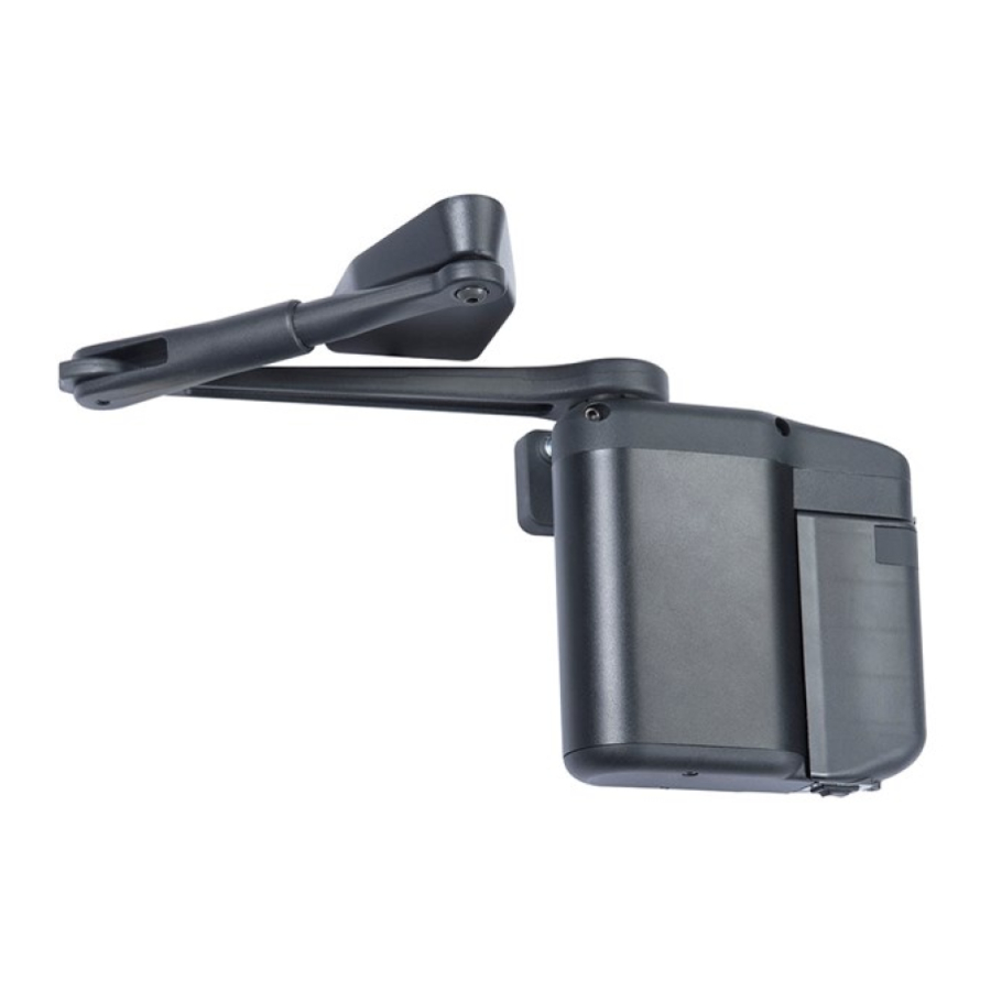
5831 Series
Installation and Operating Instructions
Door Size: 91cm - 122cm
Max Door Weight: 113kg
R-NZ
Components
Main Arm
Operator Battery
Pack
End Link
Forearm
Tools Needed
Safety
Glasses
Drill
25/64"
Adjustable
Hammer
Wrench
Copyright © 2021, ASSA ABLOY Australia Pty Limited. All rights reserved. Reproduction in whole or
in part without the express written permission of ASSA ABLOY Australia Pty Limited is prohibited.
700002AU Rev 2 06/21
Mounting
x2
Bracket
Mounting
Bracket Cover
1/16"
Tape
Hex Wrench
3 8 / "
3 16
/
"
Combination
Square
Push Side Parallel Arm on
Left Hand Door shown
x2
Decals
Wireless Pushbutton
w/Hardware Pack
Additional Tools Needed for
Optional Power Supply
Staple
Gun
Wire Stripper/
Cutter
PUSH Side Mount
Support
Arm Pivot
Bracket
Arm Mounting
Shoe
Supplied Fasteners and Tools
x10
x4
Wood
Masonry
#12 x 32mm
3/16" x 32mm
x4
x10
Through Bolt
Aluminum &
1/4-20 x 41mm
Hollow Metal
1/4-20 x 19mm
x12
x2
Washer
Mounting Post
Template
(Left Hand
and Right Hand)
x2
Arm Spacer
Rivetnut
Installation Tool
3/16"
9/64"
Hex Wrench
Advertisement
Table of Contents

Related Manuals for Lockwood ASSA ABLOY 5831 Series


Summary of Contents for Lockwood ASSA ABLOY 5831 Series
- Page 1 5831 Series Installation and Operating Instructions Door Size: 91cm - 122cm Max Door Weight: 113kg R-NZ Push Side Parallel Arm on Left Hand Door shown Components Main Arm PUSH Side Mount Template (Left Hand and Right Hand) Support Operator Battery Arm Pivot Bracket Pack...
-
Page 2: Table Of Contents
5831 Series Installation and Operating Instructions Contents Product Safety Warnings . . . . . . . . . . . . . . . . . . . . . . . . . . . . . . . . . . . . . . . . . . . . . . . . . . . . . . . . . . . . . . . . . . . . 2 General Information . -
Page 3: General Information
5831 Series Installation and Operating Instructions General Information 5831 Series is an extreme-duty, low-energy door opener designed for institutional high-traffic . It allows the door to open manually or by a RF transmitter pushbutton . As the door closes, the 5831 Series generates an electrical charge that restores power to the battery, eliminating the need for electrical power . -
Page 4: Precautions
5831 Series Installation and Operating Instructions Precautions • Improper installation or adjustment may result in • If unit will be wired to external power, do not personal injury or property damage . The operator connect source of power until instructed to do so . must be completely installed and programmed or the door must be disabled prior to leaving the •... -
Page 5: Before You Begin
5831 Series Installation and Operating Instructions Before You Begin • All dimensions are given in metric (or inches) . • If applicable, remove existing door closer . DO NOT scale drawings . • Make sure doors and frames are in good working •... -
Page 6: Push Side Operator And Arm Installation
5831 Series Installation and Operating Instructions PUSH SIDE Operator and Arm Installation Prepare Door and Frame 1 . Select right hand or left hand template and CAUTION: Desktop printers and copiers can modify Door Stop sizes greater scale if "actual size" become familiar with information . - Page 7 5831 Series Installation and Operating Instructions PUSH SIDE Operator and Arm Installation Install Arm Mounting Shoe and Support Bracket 1 . Measure door stop to determine if arm Stop Greater Than 38mm mounting shoe will be installed to face of stop Mounting or face of rabbet .
- Page 8 5831 Series Installation and Operating Instructions PUSH SIDE Operator and Arm Installation Install Arm Pivot (Figure 9) 1 . Slide arm pivot over arm shoe . Set Screws 2 . Make sure that dimension from face of door to centerline of door arm mounting hole is 162mm .
- Page 9 5831 Series Installation and Operating Instructions PUSH SIDE Operator and Arm Installation Mount Operator to Bracket Install operator mounting pins into bracket using a large adjustable wrench . Operator Mounting Bracket Cover (Figure 12) Operator Mounting Pin (2) • Narrow Stile Door: Use lower threaded holes in mounting bracket .
- Page 10 5831 Series Installation and Operating Instructions PUSH SIDE Operator and Arm Installation Install Arm WARNING: It is a safety hazard to install arm with battery pack connected . Tighten each bolt 1/4 turn at a time in a circular pattern until 1 .
-
Page 11: Pull Side Operator And Arm Installation
5831 Series Installation and Operating Instructions PULL SIDE Operator and Arm Installation Prepare Door and Frame 1 . Select right hand or left hand template and 5831 SERIES - PULL SIDED MOUNT DOOR SHOE OUTLINE become familiar with information . (Figure 17) LEFT HAND ZERO mm REVEAL REQUIRED ALIGN WITH BOTTOM OF FRAME... - Page 12 5831 Series Installation and Operating Instructions PULL SIDE Operator and Arm Installation Install Operator Mounting Bracket and Cover 1 . Install operator mounting bracket to door into holes marked in “Prepare Frame and Door” section on page 11 . (Figure 20) If door is aluminum: a .
- Page 13 5831 Series Installation and Operating Instructions PULL SIDE Operator and Arm Installation Install Arm WARNING: It is a safety hazard to install arm with battery pack connected . Shaft Extension 1 . Install shaft extension onto pinion shaft and Set Screw tighten set screw to secure .
-
Page 14: Install Battery Pack
5831 Series Installation and Operating Instructions Install Battery Pack T Channel 1 . Make sure 3 Position switch on battery pack is in OFF position . 2 . Attach battery pack wiring connector to operator receptacle . Note: Connector is keyed to prevent attaching incorrectly . -
Page 15: Install Wireless Rf Transmitter Pushbuttons
5831 Series Installation and Operating Instructions Install Wireless RF Transmitter Pushbuttons Make sure pushbuttons (Figure 30): • are located 30cm to 3 .7m from door • remain accessible from swing side when door is opened • are not located in a position where user would be in path of moving door •... -
Page 16: Install Plug-In Power Supply
5831 Series Installation and Operating Instructions Install Plug-In Power Supply (Optional) USE 24VDC POWER SUPPLY ONLY Route wire Optional plug-in power supply is into end link Wire recommended when automatic door opening from front exits back feature will be used frequently . Optional plug-in power supply is required when Power Close and/or Push and Go features are enabled . -
Page 17: Programming Operator
5831 Series Installation and Operating Instructions Programming Operator 1 . Enter programming mode . Time and Force Press and hold both “SELECT” and “ENTER” buttons Settings until LEDs 1 - 4 flash green . • Close Position LED will light red and remain lit . 2 . -
Page 18: Setting Descriptions
5831 Series Installation and Operating Instructions Setting Descriptions Opening Time: Option Features: Following an activation signal, door moves from fully • Power Close: Operator will apply a small amount closed to open check or 80°, whichever occurs first, of power if door did not close in expected close according to Table 1 . -
Page 19: Customising Settings
5831 Series Installation and Operating Instructions Customising Settings (Optional) Open/Close Time, Open and Power Close Force, 3 . With desired LED lit, rotate thumb wheel to and Hold Open Time are preset to comply with adjust setting . See Table 2 . ANSI standards for low-energy operators but may be adjusted if approved by the Authority Having 4 . -
Page 20: After Installation
5831 Series Installation and Operating Instructions Customising Settings (Optional Features) 24VDC power supply must be used if Power Close, Push and Go, or Latch Assist features are enabled . To enable or disable any feature (factory default = Off for all): 1 . -
Page 21: Troubleshooting
5831 Series Installation and Operating Instructions Troubleshooting Symptom Recommended Remedy Refer to “Adjust Door Spring Tension”, page 14 and Door Too Difficult To Open Manually reduce door-open spring tension . Refer to “Install Operator Mounting Bracket and Cover”, page 8 or page 12 and lower bracket . Arm Rubs Ensure that operator is mounted parallel to face of door . - Page 22 5831 Series Installation and Operating Instructions Troubleshooting Symptom Recommended Remedy • Refer to “Programming Operator”, page 17 and Auto Setup operator . Door Opens Too Slow • Refer to “Customising Settings”, beginning on page 19 and adjust door Hold Open time . •...
- Page 23 5831 Series Installation and Operating Instructions Troubleshooting Symptom Recommended Remedy • Ensure that operator is mounted parallel to face of door . • If bottom of operator is further away from door than top, shim top of operator mounting bracket to compensate .
- Page 24 ASSA ABLOY Opening Solutions Australia 235 Huntingdale Road, 700002AU Rev 2 06/21 Oakleigh Victoria, 3166 Australia Copyright © 2021, ASSA ABLOY Australia Pty Limited. All rights reserved. Reproduction in whole or info.au@assaabloy.com in part without the express written permission of ASSA ABLOY Australia Pty Limited is prohibited. assaabloyopeningsolutions.com.au...
Need help?
Do you have a question about the ASSA ABLOY 5831 Series and is the answer not in the manual?
Questions and answers