
Related Manuals for Raven ISOBUS


Summary of Contents for Raven ISOBUS
- Page 1 Raven Switch Box for use with ISOBUS VT Display Installation & Operation Guide P/N 016-0171-550 Rev. A 09/15 E21694 Copyright 2013, 2015...
- Page 2 Raven Industries shall not be held responsible for any modifications or repairs made outside our...
-
Page 3: Care And Maintenance
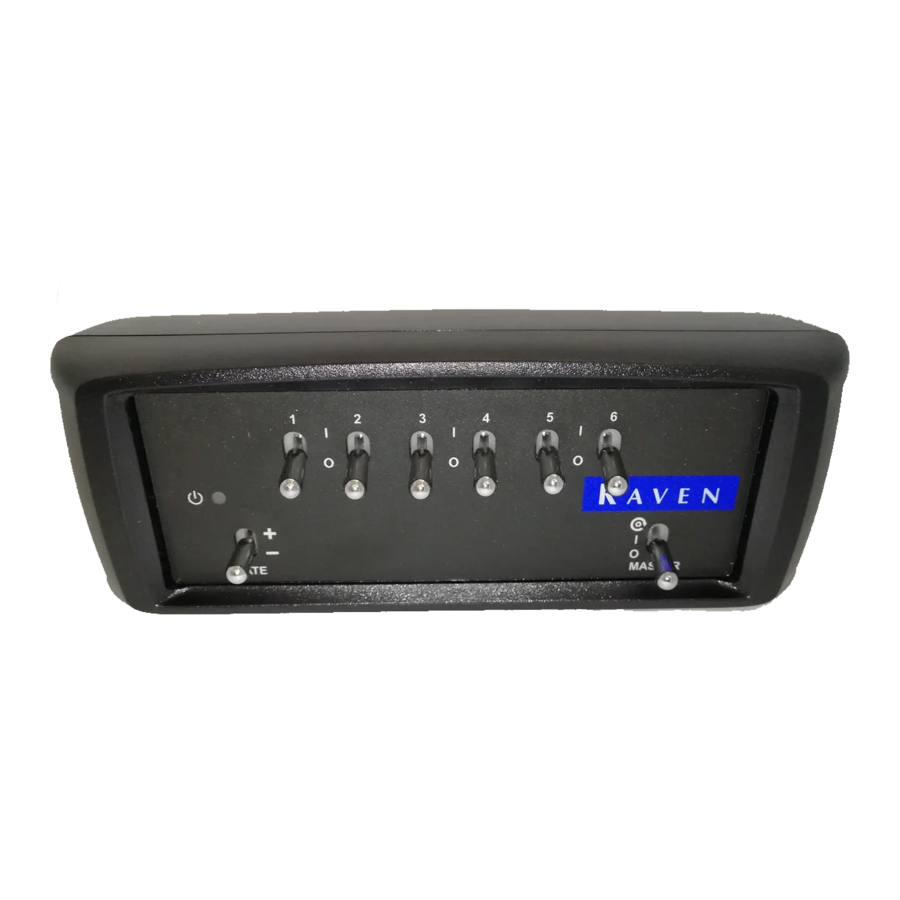
Overview The Raven Switch Box for use with ISOBUS systems is designed to interface with an ISOBUS Virtual Terminal (VT) display and a Raven ISO product control node. The switch box features: • Six section switches for quick boom or implement section control •... -
Page 4: Installation
The mounting bracket is designed to mount the switch box either above or below the Raven VT display terminal. 1. Place the switch box mounting bracket over the back panel of the Raven ISO VT display and verify the desired switch box mounting location. - Page 5 Connection The Raven Switch Box for use with ISOBUS systems connects to the ISOBUS system using the switch box cable (P/N 115-7300-023). To connect the Raven Switch Box for use with ISOBUS systems: 1. Connect the 2-pin Deutsch connector on the ISO Switch Box cable to the switched power port on the back of the ISO Switch Box.
- Page 6 Power Mounting Posts 3. If a speed signal is not provided over the ISOBUS, connect the female, 3-pin connector from a speed sensor such as a radar gun or GPS speed sensor to provide speed information for the ISOBUS system.
- Page 7 2. Remove the existing bolts to remove the mounting plate or bracket from the display terminal and remove the mounting bracket from the terminal. 3. Attach the Raven Switch Box for use with ISOBUS systems (P/N 063-0173- 143) to the mounting bracket using two 5/16” screws (P/N 311-0001-007).
- Page 8 5. Remount the display terminal, with switch box, in the vehicle cabin. Connection The Raven Switch Box for use with ISOBUS systems connects to the ISOBUS system using the CNH ISO Switch Box cable (P/N 115-0172-113). To connect the Raven Switch Box for use with ISOBUS systems: 1.
- Page 9 Connection Switched Power 9. If a speed signal is not provided over the ISOBUS, connect the female, 3-pin connector from a speed sensor such as a radar gun or GPS speed sensor to provide speed information for the ISOBUS system.
-
Page 10: Power Led
The master switch should be toggled off when powering the Raven Switch Box for use with ISOBUS systems. If the master switch is on when the unit is powered on, cycle the master switch off then back on to ensure that boom sections will enable as anticipated during operations. -
Page 11: Troubleshooting
OFF position to allow the switch box to do not turn off incorrect control sections. position Setup Issues Possible Issue Solution Cause Previous Poor CAN Check CAN connections on back of the calibration data connections Raven Switch Box. lost... -
Page 12: Job Issues
Adjust hydraulic valve and valve calibration settings to stop bed creep. Bed creep Refer to the ISOBUS Product Control manual. A fast close or PWM close valve must be selected to shut off product Wrong valve application in zero rate zones. Refer to... -
Page 13: Limited Warranty
How Can I Get Service? Bring the defective part and proof of purchase to your Raven dealer. If the dealer approves with the warranty claim, the dealer will process the claim and send it to Raven Industries for final approval. -
Page 14: Extended Warranty
How Can I Get Service? Bring the defective part and proof of purchase to your Raven dealer. If the dealer approves with the warranty claim, the dealer will process the claim and send it to Raven Industries for final approval. The freight cost to Raven Industries will be the customer’s responsibility.
Need help?
Do you have a question about the ISOBUS and is the answer not in the manual?
Questions and answers