
Subscribe to Our Youtube Channel
Related Manuals for Richard Wolf 2303


Summary of Contents for Richard Wolf 2303
- Page 1 Instruction Manual 2 3 0 3 POWER CONTROL POWER CONTROL 2303 POWER STICK M4 8564.121 POWER STICK M3 8563.111/.311 GA-A 202 / 2012-04 V6.0 / PDG 11-5360...
- Page 2 +32 92 82 92 16 france@richard-wolf.com austria@richard-wolf.com endoscopy@richard-wolf.be www.richard-wolf.com www.richard-wolf.be Marketing Office INDIA U.A.E RICHARD WOLF India Private Ltd. RICHARD WOLF Middle East JMD Pacific Square P.O. Box 500283 No. 211 A, Second Floor AL Thuraya Tower 1 Behind 32 Milestone Floor,...
-
Page 3: Table Of Contents
Contents General information ............Symbols . - Page 4 5.2.7 POWER STICK M3 ............5.2.8 POWER STICK M4 .
- Page 5 Contents 7.6.2 Machine reprocessing ............7.6.3 Checks .
-
Page 6: General Information
General information Symbols Meaning Symbols Attention, Caution Follow the instruction manual Off (power: disconnection from power/mains) On (power: connection to the power/mains) Equipotentality Fuse μ Alternating current (AC) TYPE BF APPLIED PART Socket for footswitch Alarm Ready (Triggering of function check) Signal input (CAN-BUS) Signal output (CAN-BUS) Identification of sensor field... - Page 7 Meaning Symbols Selection Confirm value Single step “Adjust speed" selector “Select speed range" selector “Device settings“ selector Oscillation rate adjustment Speed range adjustment Speed adjustment Adjust stop position (works only without footswitch) Reset to factory setting Language selection Control level “B" activated Footswitch Change between control levels “A"...
-
Page 8: Intended Use
I, are additionally marked with the code number of the notified body (0124) Intended use The POWER CONTROL 2303 in conjunction with POWER STICK M4 (8564.121) or, alternatively, POWER STICK M3 (8563.111/.311) serves to drive WOLF rotary blades/abraders and morcellators (tissue punches) for the removal of tissue in endoscopic operations. -
Page 9: Combinations
CAUTION! Reduced cutting performance and wear on the rotary blade/abrader ! If the rotary blade/abrader is pushed against the tissue at high pressure this will not improve the cutting performance but may ins- tead cause damage, increased wear and tear on the inner blade/ab- rader. -
Page 10: Requirements For The Products / Components Of A Combination
IEC/EN/UL standards When connected via a power bar under standard conditions the earth leakage current of the power bar must not exceed 5 mA. e.g. Richard Wolf video cart with "isolating transformer" GA--A 202... -
Page 11: Electromagnetic Compatibility (Emc)
Electromagnetic compatibility (EMC) NOTE: The device or system in the following called product always relates to the POWER CONTROL 2303. The product does not have any performance features classified as essential performance features in accordance with IEC/EN 60601-1. - Page 12 Guidelines and manufacturer's declaration - Electromagnetic immunity for products that are not life-supporting The product is intended for use in the environment specified below. The user should assure that the product is used in such an environment. Immunity tests IEC 60601 test level Compliance Electromagnetic environment - Guidelines Portable and mobile RF communications equipment should...
-
Page 13: Combination With Power Stick M4 And, Alternatively, Power Stick M3
Irrigation fluid container (only for 8563.311) Suction pump Irrigation tube kit (only for 8563.311) Suction tube NOTE! Instead of POWER STICK M4, POWER STICK M3 with irrigation connector (8563.311) can be connected to POWER CONTROL 2303 using adapter 2303.911. GA--A 202... -
Page 14: Illustration
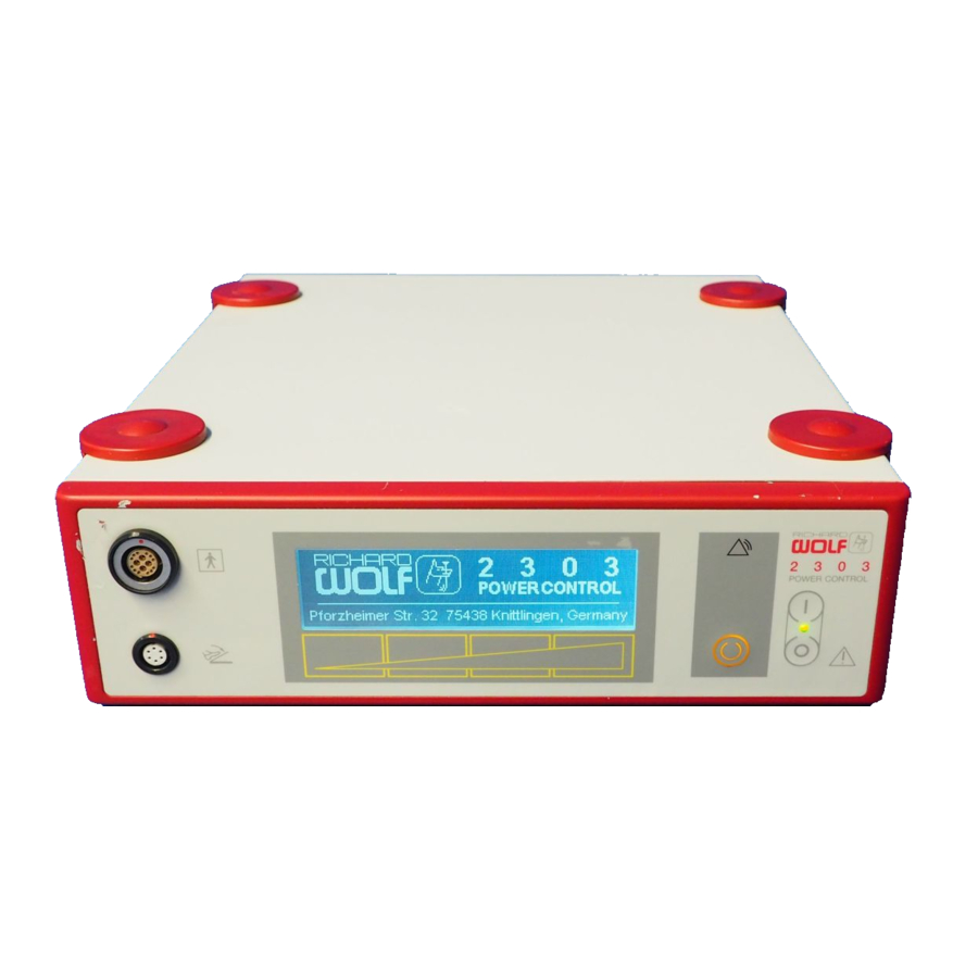
Illustration Figure: POWER CONTROL front panel 2 3 0 3 POWER CONTROL 2.1.1 Legend Power switch Sensor field (sensor surface) Socket for motorized handle (Type BF applied part) ”Alarm” indicator “Ready” button Socket for footswitch Figure: LCD display 2.2.1 Legend “Minimum speed”... -
Page 15: Legend
Figure: POWER CONTROL rear panel 11.1 11.3 11.2 FEDERAL LAW RESTRICTS THIS UNIT TO BE USED OR SOLD, EXCEPT UNDER THE SUPER-- VISION OF A MEDICAL DOCTOR. 2.3.1 Legend Power connector with fuse holder 11.1 CAN--BUS address selector Equipotential connector 11.2 CAN--BUS input Indentification plate... -
Page 16: Legend
Figure: POWER STICK M3 (8563.111 / .311) 13.5 13.2 13.8 13.10 13.6 13.3 13.4 13.9 13.1 13.7 2.5.1 Legend 13.1 Clamping chuck 13.6 Irrigation control valve (only 8563.311) 13.2 Suction connector 13.7 Rubber sleeve 13.3 Connection cable with connectors 13.8 Suction/suction and irrigation system 13.4 Irrigation connector (only 8563.311) -
Page 17: Setup
Setup WARNING! The device is not protected against explosions. Explosion hazard. Do not operate this device in areas where there is the danger of explosion. WARNING! Danger if a power supply without protective earth is used. Danger of electric shock! Connect the device only to a power supply with protective earth. -
Page 18: Preparation Of Power Stick M4
Preparation of POWER STICK M4 Z Connecting the cable to POWER STICK M4. ' Align connector (the red marking (C) must be positioned exactly be- low the suction connector) and push home. Z Connect suction tube between suction pump and suction connector on POWER STICK M4. -
Page 19: Attaching The Irrigation Adaptor (Only 8563.311)
IMPORTANT! The inner and outer blades are supplied in matched pairs. Do not mix with other blades. Z Use the adapter to connect the POWER STICK M3 connection cable to the POWER CONTROL unit. 3.3.1 Attaching the irrigation adaptor (only 8563.311) Z Check that the sealing element (13.14.2) is installed on irrigation tube (13.14.1). -
Page 20: Checks
Checks IMPORTANT! Run through the checks before and after each use. Do not use the products if they are damaged or incomplete or have loose parts. Return damaged products together with any loose parts for repair. Do not attempt to do any repairs yourself. Visual check Z Carry out the following checks: ' Check devices, instruments and accessories for damage, hygienic... -
Page 21: Function Control Of Footswitch
4.2.1 Function control of footswitch Z Connect the footswitch and the POWER STICK to the device. ' Make sure that the markings on the plug and the socket are aligned. Z Direction of rotation of rotary blade ' “CW“ rotation: Actuate the right pedal (12.4): The symbol for ”CW rotation”... -
Page 22: Function Check -- Power Stick M3 (8563.111 / .311)
4.2.3 Function check - - POWER STICK M3 (8563.111 / .311) Z The suction control valve must be easy to operate. Z Actuate the pedal at low speed: ' Rotary blade (internal part) rotates. Z Switch on suction pump, open suction control valve (push slide forward as far as it will go). -
Page 23: Use
Operating principle The POWER CONTROL can be operated with POWER STICKS M3 and M4. The device detects the type of power stick connected and adapts the settings (such as speed ranges) accordingly. The motor in the handle drives the rotary blades. It is connected to the POWER CONTROL unit via a flexible cable. -
Page 24: Operation Of Power Control Via The Sensor Surface
5.2.2 Operation of POWER CONTROL via the sensor surface At the lower edge of the LCD the current button assignment is displayed. Operation is effected via the sensor surface below the display. The button assignment changes with the context (depending on the mode of opera tion selected). -
Page 25: Language Selection
5.2.3 Language selection Z To call the option menu, keep the “Ready" button depressed for 3 seconds. ' Select language selection. Z Select language. Z Confirm entry. 5.2.4 Setting the parameters with the footswitch connected Preselecting the speed range: Z On POWER CONTROL: Z Actuate button 1, 2, 3 or 4. - Page 26 Z With the footswitch: Z Switch footswitch to control level “B". ' Symbol appears on the display. Z Keep the corresponding footswitch pedal depressed to increase or decrease the speed. Z After speed adjustment, switch footswitch back to control level “A". Selecting the direction of rotation using the footswitch: Z Connect footswitch and POWER STICK to the unit.
-
Page 27: Setting The Parameters At The Power Control, With No Footswitch Connected
5.2.5 Setting the parameters at the POWER CONTROL, with no footswitch connected To exit the submenu, press the “Back" button. Preselecting the speed range: Z Activate the setup menu by pressing the “Device settings" button. Z Call up the “Speed range selection" submenu and select the required speed range 1,2,3 or 4 ' Touching the corresponding button and maintaining the touch allows a check of the nominal speed of the speed ranges. -
Page 28: Changing The Factory Settings
5.2.6 Changing the factory settings In the option menu, the preset parameters can be changed if required. Z To call the option menu, press the “Ready" button for 3 seconds. In the option menu the following parameters can be changed: ' Define speed ranges. -
Page 29: Power Stick M3
5.2.7 POWER STICK M3 Z Arrows (A) on suction and irrigation control valves. ' The arrows indicate the direction of flow of the medium used. Z Suction/irrigation control valves: ' Valve open (suction/irrigation): push the irrigation control valve in distal direction (towards the tip of the rotary blade) as far as it will go. ' Valve closed (no suction/irrigation): push the irrigation control valve backward in proximal direction (towards the power stick) as far as it will go. -
Page 30: Operation Of Device
Operation of device CAUTION! Caution in the case of poor visibility. Tissue in the operating area may inadvertently be caught and damaged. Operate the blade only if the cutting window is easily visible. CAUTION! Do not resharpen the rotary blades / abraders! Operate the rotary blades / abraders only in liquid! Ensure sufficient suction to cool the rotary blades / abraders and to re... -
Page 31: Speed Adjustment
5.3.1 Speed adjustment Typical current speeds for rotary blades: 100 - 1500 rpm Recommended speed for rotary abraders: 800 - 3000 rpm (in special cases up to 6000 rpm ; only POWER STICK M4) Efficient speed for oscillation mode: 100 - 1500 rpm NOTE! Cutters only cut when turning clockwise. -
Page 32: Instructions And Notes On Morcellation In Urology
For each use have a spare rotary morcellator at hand. IMPORTANT ! Activate the rotary morcellator only when the tissue to be cut is pulled towards the blade. NOTE ! We recommend using the Richard WOLF PIRANHA 2208 suction pump. GA--A 202... -
Page 33: Alarms
Alarms The POWER CONTROL displays all error messages as written text on the display. Severe faults/errors, such as motor overload, device defect ive, are also issued optically and acoustically (see also section 7.1). Z “Alarm" indicator lights up and alarm is sounded if: ' the connection between POWER CONTROL and POWER STICK is incorrect ' a parting of the cable is detected... -
Page 34: Operation In The Riwo Net System
Operation in the RIWO NET SYSTEM Combination with RIWO NET SYSTEM Via the integrated CAN--BUS interface the POWER CONTROL 2303 can be integrated into the R.Wolf RIWO NET SYSTEM. Only the components approved for use with the RIWO--NET--SYSTEM must be connected to the “CAN--BUS” interface. -
Page 35: Connection To The Riwo Net System
Connection to the RIWO NET SYSTEM Touch-Screen Monitor RS- -232 z.B. Video printer Control computer Connection of headset microphone RIWO CONTROL z.B. Video recorder RS- -232 CAN- -BUS e.g. POWER CONTROL CAN- -BUS e.g. Light projector CAN- -BUS e.g. Camera CAN- -BUS termination IMPORTANT! The device system must be operated via a “Separating transformer with DC coup-... -
Page 36: Controlling The Devices Using The Riwo--Net Menu
Controlling the devices using the RIWO- -NET menu 6.5.1 Controlling the devices via the different input media Via Touch- -Screen Monitor: -- The function is selected and executed by gently touching the desired menu function (button) directly on the Touch--Screen Monitor. Via voice control: -- The same instructions/commands must be used as displayed on the Touch--Screen Monitor. -
Page 37: Main Menu
6.5.3 Main menu The main menu lists all devices connected to the RIWO NET SYSTEM. Selecting a device calls up and displays the corresponding device menu. 6.5.4 Speed range function Z The “speed range” function of the menu serves to select one of the speed ranges 1 through 4. -
Page 38: System Messages
System messages IMPORTANT! If you cannot eliminate the fault or error with the help of this table, please contact the service department or return the device for repair. ' Do not attempt to do any repairs yourself! L Depending on the status or error state the POWER CONTROL displays the following messages on the RIWO--NET menu monitor: 6.6.1 Status messages... -
Page 39: Reprocessing And Maintenance
Reprocessing and maintenance Reprocessing of device WARNING! Make sure that no humidity enters the device. Danger of electric shock. Before reprocessing switch off the device and disconnect it from the power supply. Clean the device with a soft cloth moistened with surface disinfectant, alcohol or spirit. -
Page 40: Reprocessing Of Power Stick M4 (8564.121)
Reprocessing of POWER STICK M4 (8564.121) IMPORTANT! Further notes and instructions on reprocessing are described in manual GA-J 020 "Reprocessing of RICHARD WOLF Heat-Stable Instruments", and these must be followed. 7.3.1 Manual reprocessing Wet preparation at the point of use: Z Immediately after use, immerse all parts seperately in a combined dis... -
Page 41: Machine Reprocessing
7.3.2 Machine reprocessing Machine cleaning: NOTE! For the reprocessing of POWER STICKS M4 use a special endoscope reprocessing program. Z Connect the rinsing tube of the washer/disinfector to the suction connector. 7.3.3 Assembly NOTE! Make sure that all parts are dry. Z After cleaning install the valve and connect the connection cable. -
Page 42: Reprocessing Of Power Stick M3 (8563.111 / .311)
Reprocessing of POWER STICK M3 (8563.111 / .311) IMPORTANT! Important during the entire reprocessing: the connection cable must re main connected to POWER STICK M3. The adaptor (2303.911) must only be cleaned with surface disinfectant. 7.4.1 Manual reprocessing Wet preparation at the point of use: Z Immediately after use immerse all parts seperately in a combined dis... -
Page 43: Machine Reprocessing
Manual cleaning/disinfection: Z Thoroughly rinse all parts of POWER STICKS M3 first with cold and then with warm water under the tap (The connection cable must re main connected to POWER STICK M3). Z Immerse all parts of POWER STICKS M3 in a combined cleaning and disinfecting solution. -
Page 44: Assembly
7.4.3 Assembly After cleaning, all accessory parts must be assembled: Z Place cover (13.10) onto suction/irrigation system (13.8). ' Install cover in a rotary motion in counter-clockwise direction and then push down (the recesses must be on the side of the valves). Z Lubricate the suction and irrigation valve pistons spearingly with endo... -
Page 45: Sterilization
7.4.5 Sterilization Steam sterilization: Z Steam-sterilize the POWER STICK M3 at 134 C (272 F) using a fractional pre-vacuum method. ' Open the suction and irrigation control valves to allow the steam to flow freely. ' The connection cable must remain connected to POWER STICK M3. Steris and Sterrad sterilization procedures:... -
Page 46: Machine Reprocessing
7.5.2 Machine reprocessing Machine cleaning/disinfection: Z Irrigation tube (16.34.1) must be rinsed out manually before machine cleaning. Z Connect irrigation adapter to the corresponding connectors of the washer/disinfector rack. NOTE! For the reprocessing of the irrigation adapter use the special endoscope reprocessing program. -
Page 47: Reprocessing Of The Re-Usable Rotary Blades, Abraders And Morcellators
Reprocessing of the re-usable rotary blades, abraders and morcellators 7.6.1 Manual reprocessing Wet preparation at the point of use: Z Immediately after use, immerse all parts seperately in a combined dis infecting and cleaning solution. ' This prevents microorganisms from being transmitted and contamin ant residues from drying on the instrument. -
Page 48: Technical Description
Technical description Trouble shooting NOTE! If you cannot eliminate the faults or errors with the help of this table, please contact the service department or return the device for repair. ' Do not attempt to do any repairs yourself! 8.1.1 POWER CONTROL Fault/error Possible cause... -
Page 49: Technical Data Of Power Control
2303.001 50 / 60 0.8 -- 0.44 T 1.6 L 220 -- 240 100 -- 127 2303.011 (USA) 50 / 60 0.8 -- 0.44 T 1.6 L 250V 220 -- 240 Electromagnetic compatibility (EMC) in acc. with EN / IEC 60601--1--2... -
Page 50: Technical Data Of Power Stick
Technical data of POWER STICK Length Cross section Weight Speed Model/type Designation 8564.021 POWER STICK M4 25 x 28 100 -- 6000 8564.851 Connection cable 3000 8563.111 /.311 POWER STICK M3 27 x 31 100 -- 3000 8563.851 Connection cable 3000 Protection against electric shock Type BF applied part... -
Page 51: Spare Parts And Accessories
Units Model/type Designation 64 268.019 Device fuse T 1.6 L 250V (10/pkg) 2440.03 Power cable (Europe), 3.0 m N710006 Power cable (USA), 8.0 ft 2303.901 Footswitch 2303.911 Adapter for POWER STICK M3 8.6.2 POWER STICK M4 Units Model/type Designation 8564.021 POWER STICK M4 8564.851... -
Page 52: Reusable Rotary Blades And Abraders
8.6.4 Reusable rotary blades and abraders dia. 2.0 dia. 3.0 dia. 3.5 dia. 4.5 dia. 5.5 dia. 6.0 Illustration Color Designation 8568.011 yellow Resector 8564.011 8568.031 8569.011 8567.011 8568.032 blue Incisor 8567.051 8568.051 End Cutter 8567.561 8568.561 green... -
Page 53: Reusable Rotary Blades And Abraders For Spinal Surgery (Power Stick M4)
8.6.6 Reusable rotary blades and abraders for spinal surgery (POWER STICK M4) Working dia. 2.5 dia. 3.0 dia. 4.0 dia. 4.5 Illustration Color Designation length yellow Nucleus Resector 8792.313 yellow Nucleus Resector 89970.4003 yellow Nucleus Resector 89970.1003 yellow Nucleus Resector... -
Page 54: Replacing Parts On Power Stick M4 (8564.121)
Replacing parts on POWER STICK M4 (8564.121) 8.7.1 POWER STICK M4 connection cable Z Disassembly of connection cable: ' Hold and pull off plug by the rubber sleeve. Z Assembly of connection cable: ' Turn the plug so that it is aligned (the red marking (C) must be ex- actly below the suction tube) and push in as far as it will go. -
Page 55: Device Fuses
Device fuses CAUTION! The specification of the fuses in the device must correspond with the fuse ratings on the identification plate. Use only the fuses specified in the spare parts list. L Power input connector with fuse holder Z Switch off the device and disconnect the power cable from the wall socket and from the power input connector of the device.
Need help?
Do you have a question about the 2303 and is the answer not in the manual?
Questions and answers