
Related Manuals for Richard Wolf PowerDrive ART1


Summary of Contents for Richard Wolf PowerDrive ART1
- Page 1 Instruction Manual ART1 POWER DRIVE 2304.007 Power Stick M4 , M5/3 , M5/0 Micro Stick S1 Power Drill M1 GA-A 238-USA / 2012-10 V5.0 (RW: 2012-04 V5.0 / ÄM: PDG 11-5390) / ECO 2012-0554...
- Page 2 +32 92 82 92 16 info@richard--wolf.at endoscopy@richard--wolf.be endoscopes@richardwolf.fr www.richard--wolf.at www.richard--wolf.be Marketing Office INDIA U.A.E RICHARD WOLF India Private Ltd. RICHARD WOLF Middle East JMD Pacific Square P.O. Box 500283 No. 211 A, Second Floor AL Thuraya Tower 1 Behind 32 Milestone Floor,...
-
Page 3: Table Of Contents
Contents General information ............Symbols . - Page 4 ..............Operating principle .
- Page 5 Contents Technical data of foot switch ..........Technical data of motorized handle .
-
Page 6: General Information
General information Symbols Meaning Symbols Device Attention, consult ACCOMPANYING DOCUMENTS Off (no power: disconnection from the line voltage) On (power: connection to the line voltage) Potential equalization Fuse Alternating current (AC) μ TYPE BF APPLIED PART Socket for foot switch Signal input (CAN-BUS) Signal output (CAN-BUS) Data transfer... - Page 7 Meaning Symbols Direction of rotation "cw" locked "Oscillation" locked Defective tool memory "Increase value" "Increase value" "Decrease value" Touchscreen display - - user selection User selection Language setting Contrast / brightness menu Contrast / brightness adjustment Brightness adjustment Invert display Activate / deactivate handle buttons Device data Delete data...
- Page 8 Meaning Symbols Foot switch Single-step mode (toggle mode) Direction of rotation “counter-clockwise“ Direction of rotation “oscillation“ Direction of rotation “clockwise“ "Increase value" "Decrease value" Power Drill handle Lock / unlock Direction of rotation “counter-clockwise“ Direction of rotation “clockwise“ Steam-sterilizable General information Order number Lot identification number Manufacturing date...
-
Page 9: Intended Use
POWER DRIVE ART1 In conjunction with a motorized handle (e.g. Power Stick M5/3): it is used as a drive unit for Richard Wolf rotary blades / burrs to remove tissue in endoscopic interventions. Simultaneous suction allows the continuous removal of the ablated tis... -
Page 10: Contraindications
General notes and instructions for use CAUTION! All Richard Wolf disposable rotary blades and abraders are double- packaged in sterile packaging material and are designed for single use only. Store any products which are not used in the storage packaging (exterior cardboard box). - Page 11 IMPORTANT! As a result of the differing anatomies, it is not possible to quantify the irrigation or suction flow. The user must adapt the flow to the situation. GA--A 238--USA...
-
Page 12: Potential Equalization
IEC/EN/UL standards When connected via a power bar under standard conditions the earth leakage current of the power bar must not exceed 5 mA. e.g. Richard Wolf video cart with "isolating transformer" GA--A 238--USA... -
Page 13: Electromagnetic Compatibility (Emc)
IMPORTANT! The persons combining products to form a system are responsible for not impairing the system's compliance with performance and safety requirements, and that the technical data and the intended use are adequately fulfilled. Possible electromagnetic or other interference that may occur between the product and other products can cause faults or malfunctions. - Page 14 Guidelines and manufacturer's declaration - Electromagnetic immunity for products that are not life-supporting The product is intended for use in the environment specified below. The user should assure that the product is used in such an environment. Immunity tests IEC 60601 test level Compliance Electromagnetic environment - Guidelines Portable and mobile RF communications equipment should...
-
Page 15: Combination With Motorized Handles And Power Drill
Combination with motorized handles and power drill 1.8.1 Legend ART1 POWER DRIVE 2304 Power Drill M1 Power Stick M4, M5/0, M5/3 Exchangeable tool holders or Micro Stick S1 Foot switch Suction pump Suction tube GA--A 238--USA... -
Page 16: Illustration
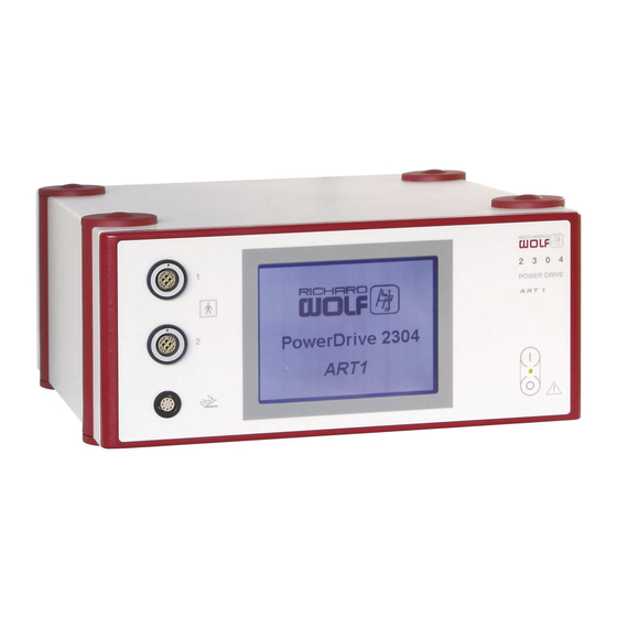
Illustration ART1 POWER DRIVE front panel Fig. 2 2.1.1 Legend Power ON/OFF switch Socket for foot switch Touchscreen Sockets for handles Touchscreen Dr. Bones Fig. 3 2.2.1 Legend Adjustment of different parameters Pre-setting for direction of rotation of handle - only Micro Stick S1 Display of “set value"... -
Page 17: Power Drive Art1 Rear Panel
ART1 POWER DRIVE rear panel FEDERAL LAW RESTRICTS THIS UNIT TO BE Fig. 4 USED OR SOLD, EXCEPT UNDER THE SUPER-- VISION OF A MEDICAL DOCTOR. 2.3.1 Legend Power input socket with fuse holder CAN-BUS input Potential equalization connector CAN-BUS output Identification plate Data interface (for service only) Foot switch... -
Page 18: Illustration Of Power Stick M5/3
Illustration of Power Stick M5/3 11.2 11.3 11.5 11.4 With fixed connection cable 11.1 11.5.2 11.5.3 11.5.1 11.4.1 With removable connection cable Fig. 6 Legend 11.1 Tool locking mechanism 11.5 Button cluster 11.2 Valve element 11.5.1 "Oscillation" button (secondary function: "single step") 11.3 Suction connector 11.5.2... -
Page 19: Illustration Of Power Stick M5/0
Illustration of Power Stick M5/0 12.3 12.2 12.4 With fixed connection cable 12.1 12.4.1 With removable connection cable Fig. 7 Legend 12.1 Tool locking mechanism 12.3 Suction connector 12.2 Valve element 12.4 Connection cable 12.4.1 Removable connection cable GA--A 238--USA... -
Page 20: Illustration Of Micro Stick S1
Illustration of Micro Stick S1 13.3 13.2 13.1 13.4 13.5 Fig. 8 Legend 13.1 Tool locking mechanism 13.4 "ON/OFF" button 13.2 Valve element 13.5 Firmly connected connection cable 13.3 Suction connector Illustration of Power Stick M4 14.4 14.5 14.3 14.2 14.1 Fig. -
Page 21: Power Drill M1
Power Drill M1 15.6 15.1 15.7 15.2 15.8 15.3 15.9 15.4 15.10 15.5 15.11 89980.0100 15.12 89980.0400 Fig. 10 2.9.1 Legend Handle Tool holder 15.1 Locking mechanism 15.6 Sagittal saw adapter 15.2 “CW" button 15.7 Reciprocal saw adapter 15.3 “CCW" button 15.8 Drill chuck 15.4... -
Page 22: Set-Up
Set-up WARNING! The device is not protected against explosions. Explosion hazard. Do not operate this device in areas where there is a danger of explosion. CAUTION! Liquid can enter the device through the louvers. Danger of electric shock and electric short circuit in the device. Do not place any products or objects above the device from which liquids can drip down onto the device. -
Page 23: Preparation - Power Drive Art1
IMPORTANT! Never pull the connection cable. Never squeeze, pinch or excessively bend the connection cable as this can result in damage to the wiring followed by malfunction of the motor ized handle. IMPORTANT! Initial set-up: To allow the device to adapt to the ambient temperature, leave it in the packaging for another two hours before unpacking. -
Page 24: Preparation Of Micro Stick S1
Preparation of Micro Stick S1 Z Connect the suction tube to the suction pump and the other end to the suction connector of the Micro Stick. Set the suction valve to “OFF". NOTE! The irrigation pressure can be changed either via the height difference (hydrostatic pressure) or a pressure sleeve in accordance with the work... -
Page 25: Preparation - Power Drill M1
Preparation - Power Drill M1 Z Connect the mains/power cable to Power Drill M1. ' Align the plug (the red markings must be aligned) and push home. Z Place the required tool holder into the handle (Fig. 5). ' Make sure that the pins in the Power Drill receptacle engage in the grooves of the tool holder. -
Page 26: Checks
Checks IMPORTANT! Run through the checks before and after each use. Do not use products which are damaged, incomplete or have loose parts. Return damaged products together with any loose parts for repair. Do not attempt to do any repairs yourself. Visual check Z Check the device and accessories for damage, loose or missing parts, hygienic conditions and completeness. -
Page 27: Function Check
Function check NOTE! Make sure the attached tools are immersed in liquid and are not operated in dry condition (it is necessary to dissipate the heat generated by mechanical friction). Z Switch on the power switch. ' If no handle is connected, the message “no hand piece connected!” is displayed. -
Page 28: Function Check Of Micro Stick S1
4.2.3 Function check of Micro Stick S1 Z Immerse the attached tool in liquid (the window of the outer blade must be open), switch on the suction pump and open the suction valve. ' The liquid must be evacuated. If the suction channel is clogged, clean with a cleaning gun. -
Page 29: Use
Operating principle ART1 The POWER DRIVE detects the connected motorized handle and, depending on the motorized handle, also the tools connected to the handle. In the case of Power Stick M4 and Power Drill M1, only the handle, not the tool or the connected tool holder, is detected. The rotary blades and tools are driven by a motor integrated in the ART1 corresponding handle and connected to the POWER DRIVE... -
Page 30: Foot Switch Mode In 2-Pedal Or 3-Pedal Mode
5.2.3 Foot switch mode in 2-pedal or 3-pedal mode The user menu allows for a switch-over between 2-pedal and 3-pedal mode. In 2-pedal mode, the left foot switch is assigned “oscillation" as the direction of rotation, the clockwise rotation is omitted (see Section 4.2.1). 5.2.4 Emergency shut-down of handle motor In the case of a defective pedal or cable (handle motor does not stop or... - Page 31 The following parameters are displayed: Loading tool data Loading tool data: When a tool is inserted into the handle, the screen "Loading tool data" appears together with a progress bar. Set speed After loading the tool data the Recognized tool screen "Recognized tool"...
- Page 32 Tool removed After having removed a tool, the display shows "Tool removed". End of service life The factory service life setting is 60 minutes. Once an instrument has reached the service life of over 60 minutes, the "End of service life" appears on the display.
-
Page 33: Controlling Power Stick M5/3 Via Its Control Buttons
5.2.6 Controlling Power Stick M5/3 via its control buttons Primary function of button assignment: Z Pushing the corresponding button briefly triggers the primary function. Pushing any button stops the function. -- “Oscillation” (11.5.1) 11.5.2 -- “Clockwise” (11.5.2) -- “Counter--clockwise” (11.5.3) Secondary function of button assignment: Z Pushing the corresponding button longer (>... -
Page 34: Controlling Power Drill M1
5.2.8 Controlling Power Drill M1 Z The buttons serve to adjust the speed (infinitely variable) up to the maximum speed set at the device, i.e. the maximum possible speed of the Power Drill. ' The "Oscillation" setting is not possible. Z The selector switch allows the key functions to be inhibited as shown in figure 14. -
Page 35: Setting The Parameters On The Device And Using The Foot Switch
Setting the parameters on the device and using the foot switch See also Section 2. Display Function Remark Touchscreen - Mode level The selected speed is adjusted by means of the “+" and “-" buttons or with a linear movement across the width of the graphical Speed adjustment interface. - Page 36 Display Function Remark Foot switch In the corresponding pedal position the se Adjusting the speed lected speed can be increased or de creased within the defined speed range. In three pedal mode, it is possible to choose between “CCW" and “CW" (acceler ator pedal function).
- Page 37 Display Function Remark Touchscreen - user interface Factory settings Call the user menu using the “Factory Set Calling the user menu tings" button or the Select user button Dr. Bones Factory settings - Selecting the language - Changing display settings - Foot switch mode, 2- or 3-pedal mode - Activating and deactivating the handle...
- Page 38 Display Function Remark Touchscreen - user interface Activate / de-activate The handle buttons can be de-activated in handles a user-specific manner. The “deleting user data" button deletes the user irrevocably from the list. Really delete the user To confirm the deletion for the user press from the list ? “Enter"...
-
Page 39: Device Operation
Device operation CAUTION! Be careful in the case of insufficient operative view. Tissue in the operating area can inadvertently get into the cutting win dows and be injured. Operate the blade only if the cutting window is clearly visible. CAUTION! Do not re- sharpen the rotary blades or abraders! Operate the rotary blades / abraders only in liquids! Ensure sufficient suction to cool the rotary blades / abraders and to re... -
Page 40: Speed Setting
5.4.1 Speed setting NOTE! Cutters / abraders only cut in clockwise direction. High speeds increase the friction. This may result in wear and tear and crack formation in the cutters / abraders. CAUTION! Mind high speeds of 3,000 rpm Danger of thermal damage to the tissue from excessive heat. Adequate irrigation is necessary to guarantee sufficient cooling of the tissue and the tool. -
Page 41: Error Messages
Error messages The error messages are always issued together with a sound signal. Error message Possible cause Corrective action “POWER DRIVE” device error! Device error ' Contact the service department Please contact authorized service technician ! Foot switch was actuated when ' release actuated button connected Foot switch defective... -
Page 42: Operation In The Riwo Net System
Operation in the RIWO NET SYSTEM Combination with RIWO NET SYSTEM Via the integrated CAN-BUS interface the POWER DRIVE ART1 can be integrated into the R.Wolf RIWO NET SYSTEM. Only the components approved for use with the RIWO-NET-SYSTEM must be connected to the “CAN-BUS" interface. The components must meet the requirements of the latest instruction manual for the RIWO-NET-SYSTEM, section on “Combinations". -
Page 43: Connection To The Riwo-Net System
Connection to the RIWO-NET SYSTEM Touchscreen Monitor RS- -232 e.g. video printer Control computer Connection of headset RIWO CONTROL microphone e.g. video recorder RS- -232 CAN- -BUS e.g. POWER ART1 DRIVE CAN- -BUS e.g. light projector CAN- -BUS e.g. camera CAN- -BUS termination Fig 26 IMPORTANT! -
Page 44: Controlling The Devices Using The Riwo-Net Menu
Controlling the devices using the RIWO-NET menu 6.4.1 Controlling the devices via the different input media Via Touch- -Screen Monitor: -- The function is selected and executed by gently touching the desired menu function (button) directly on the Touch--Screen Monitor. Via voice control: -- The same instructions/commands must be used as displayed on the Touch--Screen Monitor. -
Page 45: Main Menu
Please note: The “direction of rotation” can only be selected if the Micro Stick S1 is connected. 2nd menu page Legend Back to the previous menu page 6.4.3 Main menu In the main menu, all devices connected to the RIWO--NET system are listed. -
Page 46: System Messages
System messages IMPORTANT! If you cannot eliminate the faults with the help of this table, please contact the service department or send in the device for repair. Do not attempt to do any repairs yourself! ART1 L Turning on the operating or error stage, the POWER DRIVE causes the following messages to be displayed on the RIWO-NET menu monitor: 6.5.1... -
Page 47: Cleaning, Sterilization And Maintenance
Cleaning, sterilization and maintenance ART1 Disinfecting of POWER DRIVE WARNING! Make sure that no humidity enters the device. Danger of electric shock. Before disinfecting switch off the device and disconnect it from the power supply. Clean the device with a soft cloth moistened with a surface disinfectant that is approved for cleaning/disinfecting surfaces on devices, universal device carts and auxiliary carts. -
Page 48: Reprocessing Procedures
Strictly adhere to the maximum immersion time in the disinfectants used, as described by the manufacturers. The following table (see next page) describes the reprocessing procedure for the individual products validated by Richard Wolf. IMPORTANT! When used as intended and when following the instruction manual, it is not necessary to limit the number of possible reprocessing cycles. - Page 49 Illustrations for reprocessing instructions IMPORTANT! Plastic parts must not be cleaned with metal or sharp-edged tools (e.g. brushes with sharp edges). Fig. 28 Product Power Stick M4, M5/0, M5/3, Micro Stick S1 Reprocessing guide: Preparation at the Directly after use, remove any coarse soiling from the instruments. If there are more than 6 h between use and repro point of use: cessing, rinse out hollow spaces with a syringe filled with water.
- Page 50 Product Power Stick M4, M5/0, M5/3, Micro Stick S1 Reprocessing guide: IMPORTANT ! Sterilization: Do not connect the removable connection cable to the motorized handle during sterilization. Sterilize separately. Motorized handles with firmly connected connection cable can be sterilized together with the cable. Set the valve (13.2/14.2) to ON to allow a free flow of steam.
-
Page 51: Rotary Blades / Cutters
7.3.2 Rotary blades / cutters IMPORTANT! Disposable rotary blades / cutters are designed for one single use only and must be discarded after use following the country-specific regulations. Product Reusable rotary blades / cutters Reprocessing guide: Preparation at the Directly after use, remove any coarse soiling from the instruments. point of use: If there are more than 6 h between use and reprocessing, rinse out hollow spaces with a syringe filled with water. - Page 52 Product Reusable rotary blades / cutters Reprocessing guide: Validation: The validation for reprocessing was carried out with the following materials and machines: Manual ' Cleaning agent: Cleaner 0.5% neodisher MediClean (Dr. Weigert) ' Disinfectant: Cidex (Advanced Sterilization Products) Machine ' AWD: Miele G7735CD ' Washer-disinfector rack: Miele E 440/1...
-
Page 53: Power Drill M1 With Accessories
7.3.3 Power Drill M1 with accessories Disassembly before cleaning Z Disconnect the connection cable (B) and the tool holder (E) from the Power Drill. Fig. 29 Illustrations for reprocessing instructions Fig. 30 Product Power Drill M1 and accessories Reprocessing guide: Preparation at the Directly after use, remove any coarse soiling from the instruments. -
Page 54: Low-Temperature Sterilization
Z Ethylene oxide gas (EO) 7.4.2 Alternate sterilization methods For possible alternate sterilization methods, refer to our website, www.richardwolfusa.com under „Reprocessing & Sterilization“, for lists of the Richard Wolf instruments that have been approved for various repro cessing methods. GA--A 238--USA... -
Page 55: Technical Description
Technical description Troubleshooting NOTE! If you cannot eliminate the faults with the help of this Table, please contact the service department or send in the device for repair. Do not attempt to do any repairs yourself! Fault Possible cause Corrective action Device does not function Main/power switch is not ON 'Actuate the main/power switch... -
Page 56: Technical Data Of Power Drive Art1
ART1 Technical data of POWER DRIVE Voltage Frequency Power Current Fuse Model consumption rating μ 2304.007 (USA) 50 / 60 T 2.0 L 250V Electromagnetic compatibility (EMC) in acc. with IEC / EN 60601--1--2 Medical Devices Directive 93/42/EEC Class II a Protection class in acc.with IEC / EN 60601--1;... -
Page 57: Technical Data Of Motorized Handle
Technical data of motorized handle Speed Length Cross- -section Weight Product no. Designation range [mm] [mm] [rpm] Power Stick M4 8564.021 25 x 28 100 -- 6000 (with removable connection cable 3.0 m) Power Stick M5/3 89955.0003 25x32 300--16000 (with removable connection cable 3.0 m) Power Stick M5/3 8995500031... -
Page 58: Operating, Storage, Transport And Shipping Conditions
Protection against electric shocks Type BF applied part Degree of protection against the ingress of liquids IP X7 Degree of protection when used in the presence of flam- The device is not protected against explosions mable mixtures (Do not operate this device in flammable atmosphere) Mode / duty factor Continuous operation duty type with load interval INT.1 min. -
Page 59: Spare Parts And Accessories
Spare parts and accessories Taking account of their relevant technical data and intended use, the products are mutually compatible and combinable. For added clarity, please refer to the current catalog sheets and pamphlets or contact Richard Wolf or their representatives. All spare parts and accessories may not be available in all markets. ART1 8.7.1 POWER DRIVE... -
Page 60: Reusable Rotary Blades / Cutters (Micro Stick S1)
8.7.6 Reusable rotary blades / cutters (Micro Stick S1) Diameter Working length Product no. Designation Color code 89971.0032 Resector green-beige 89971.0033 Resector green-beige 89971.0034 Resector green-beige 89971.0113 Oval Resector Plus green-beige 89971.0114 Oval Resector Plus green-beige 89971.0503 Hooded Round Burr gray 89971.0254 Curved Meniscus Resector, convex... -
Page 61: Disposable Rotary Blades / Cutters (Power Sticks M5/0 And M5/3)
Diameter Working length Product no. Designation Color code 89975.0505 Hooded Round Burr gray-white 89975.0516 Unhooded Round Burr gray-white 89975.0553 Oval Burr gray-white 89975.0555 Acromionizer gray-white 89975.0558 Acromionizer gray-white 89975.0253 Curved Meniscus Resector, convex black 89975.0254 Curved Meniscus Resector, convex black 89975.0255 Curved Meniscus Resector, convex black... -
Page 62: Reusable Rotary Blade / --Cutter (Power Stick M4)
Diameter Working length Product no. Designation Color code 49975.0516 Unhooded Round Burr gray-white 49975.0553 Oval Burr gray-white 49975.0555 Acromionizer gray-white 49975.0558 Acromionizer gray-white 49975.0263 Curved Meniscus Resector, concave black 49975.0264 Curved Meniscus Resector, concave black 49975.0265 Curved Meniscus Resector, concave black 49975.0253 Curved Meniscus Resector, convex... -
Page 63: Reusable Rotary Blades / Cutters For Spinal Surgery (Power Stick M4)
Diameter Working length Product no. Designation Color code 126.5 4567.041 Serrated Scalloped Resector yellow 126.5 4568.041 Serrated Scalloped Resector yellow 126.5 4569.041 Serrated Scalloped Resector yellow 126.5 4567.571 End Cutter 126.5 4568.571 End Cutter 126.5 4569.571 End Cutter 126.5 4567.211 Shaver Cutter green 126.5... -
Page 64: Disposable Sagittal Sawblades (Power Drill M1)
Diameter Working length Product no. Designation Color code 899751405 Diamond burr gray-white 899751505 Oval burr with lateral protection grauweiß 899751555 Excentric oval burr gray-white ' for complete overview please see catalog sheets 8.7.14 Disposable sagittal sawblades (Power Drill M1) Thickness Thickness Working Thickness... -
Page 65: Disposable Drill Bits (Power Drill M1)
8.7.17 Disposable drill bits (Power Drill M1) Diameter Total length Length of spiral Product no. Designation 49970.1501 Drill bit 49970.2002 Drill bit 49970.2503 Drill bit 49970.2704 Drill bit 49970.3205 Drill bit 49970.3206 Drill bit 49970.3507 Drill bit 49970.3508 Drill bit 49970.3509 Drill bit 49970.3510... -
Page 66: Replacement Of Spare Parts
Replacement of spare parts 8.8.1 O-ring for valve lever Micro Stick S1 Disassembly: Z Cut open the defective O-ring (A) and remove. Assembly: Z Push home new the O-ring. ' Before assembly, sparingly grease the O-ring with special grease (200.11). 8.8.2 Device fuses CAUTION! -
Page 67: Literature
Literature IMPORTANT! As we cannot provide a comprehensive bibliography we would ask users to keep themselves informed of all new developments in this field. Z Die arthroskopische Synovialektomie Knie--, Schulter--, Ellenbogen-- und Sprunggelenk -- OP--Technik und Ergebnisse Wilhelm Klein 1096/4 -- Ausgabe 9 , Stiftung zur Förderung der Arthroskopie, Postfach 29, D--78501 Tuttlingen, Tel. -
Page 68: Warranty And Customer Service
Contact Richard Wolf if you have any question (1) whether replacement of a part or a repair is authorized by Richard Wolf, or (2) whether you have complete instructions and specifications for part replacement or repair.
Need help?
Do you have a question about the PowerDrive ART1 and is the answer not in the manual?
Questions and answers