Agilent Technologies 89410A Installation And Verification
Hide thumbs
Also See for 89410A:
- Service manual (184 pages) ,
- Getting started manual (88 pages) ,
- Operator's manual (339 pages)
Table of Contents
Advertisement
Quick Links
Advertisement
Table of Contents

Related Manuals for Agilent Technologies 89410A


Summary of Contents for Agilent Technologies 89410A
- Page 1 Agilent Technologies 89410A Installation and Verification Agilent Technologies Part Number 89410-90093 Printed in U.S.A. Print Date: May 2000 © Agilent Technologies, Inc., 2000. All rights reserved. 8600 Soper Hill Road Everett, Washington 98205-1298 U.S.A.
- Page 2 The Agilent 89410A at a Glance...
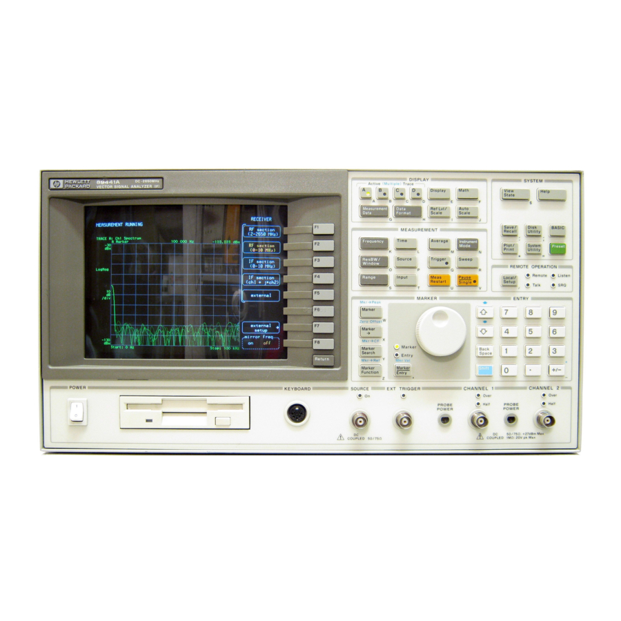
- Page 3 AY7 to select display options for that data. (second input channel) is not installed. For more details on the Agilent 89410A front panel, display the online help topic ‘’Front Panel.’’...
- Page 4 This page left intentionally blank.
- Page 5 89410A, order 89410U followed by the option number. To convert your 89410A DC-10 MHz Vector Signal Analyzer to an 89441A DC-2650 MHz Vector Signal Analyzer, order an 89431A. To order an option when converting your 89410A to an 89441A, order 89431A followed by the option number. IMPORTANT To convert older HP 89410A analyzers (serial numbers below 3416A00617), contact your nearest Agilent Technologies sales and service office.
- Page 6 (see title page in manual) Operator’s Guide Agilent Technologies 89410A Getting (see title page in manual) Started Guide Agilent Technologies 89410A Installation and Verification Guide (see title page in manual) Agilent Technologies 89400-Series GPIB Command Reference (see title page in manual) GPIB Programmer’s Guide...
- Page 7 The accessories listed in the following table are available for the Agilent 89410A. Available Accessories Part Number Agilent 89411A 21.4 MHz Down Converter Agilent 89411A 89400-Series Using Instrument BASIC Agilent 89441-90013 Instrument BASIC User’s Handbook Agilent E2083-90005 Spectrum and Network Measurements Agilent 5960-5718 Box of ten 3.5-inch double-sided, double-density disks...
- Page 8 This page left intentionally blank viii...
- Page 9 Failure to comply with these precautions or with specific warnings elsewhere in this manual violates safety standards of design, manufacture, and intended use of the instrument. Agilent Technologies, Inc. assumes no liability for the customer’s failure to comply with these requirements.
- Page 10 FUSES Only fuses with the required rated current, voltage, and specified type (normal blow, time delay, etc.) should be used. Do not use repaired fuses or short-circuited fuse holders. To do so could cause a shock or fire hazard. DO NOT OPERATE IN AN EXPLOSIVE ATMOSPHERE Do not operate the instrument in the presence of flammable gases or fumes.
- Page 11 Safety Symbols Warning, risk of electric shock Caution, refer to accompanying documents Alternating current Both direct and alternating current Earth (ground) terminal Protective earth (ground) terminal Frame or chassis terminal Terminal is at earth potential. Standby (supply). Units with this symbol are not completely disconnected from ac mains when this switch is off...
- Page 12 Notation Conventions Before you use this book, it is important to understand the types of keys on the front panel of the analyzer and how they are denoted in this book. Hardkeys Hardkeys are front-panel buttons whose functions are always the same. Hardkeys have a label printed directly on the key.
- Page 13 In This Book This guide provides instructions for installing and verifying the performance of the Agilent 89410A DC-10 MHz Vector Signal Analyzer. Chapter 1, ‘’Preparing the Analyzer for Use,’’ provides step-by-step instructions for getting the analyzer ready to use and instructions on cleaning the screen, storing, and transporting.
- Page 14 This page left intentionally blank.
-
Page 15: Table Of Contents
Table of Contents 1 Preparing the Analyzer for Use To do the incoming inspection 1-5 To install the analyzer 1-7 To change the line-voltage selector switch 1-8 To change the fuse 1-9 To connect the analyzer to a LAN 1-10 To connect the analyzer to a serial device 1-10 To connect the analyzer to a parallel device 1-11 To connect the analyzer to an GPIB device 1-11... - Page 16 To set up the external trigger test 2-26 To set up the external arm test 2-27 To set up the harmonic distortion test 2-28 To set up the input capacitance test 2-30 To set up the input resistance test 2-32 To set up the dc offset test 2-33 To set up the spurious signals test 2-34 To set up the noise test 2-35...
-
Page 17: Preparing The Analyzer For Use
Preparing the Analyzer for Use... - Page 18 Preparing the Analyzer for Use This chapter contains instructions for inspecting and installing the Agilent Technologies 89410A DC-10 MHz Vector Signal Analyzer. This chapter also includes instructions for cleaning the screen, transporting and storing the analyzer. Power Requirements The analyzer can operate from a single-phase ac power source supplying voltages as shown in the table.
- Page 19 Warning DO NOT interrupt the protective earth ground or ‘’float’’ the Agilent 89410A DC-10 MHz Vector Signal Analyzer. This action could expose the operator to potentially hazardous voltages. The analyzer is equipped with a three-conductor power cord that grounds the analyzer when plugged into an appropriate receptacle.
- Page 20 Preparing the Analyzer for Use Agilent 89410A *The number shown for the plug is the industry identifier for the plug only, the number shown for the cable is an Agilent part number for a complete cable including the plug. **UL listed for use in the United States of America.
-
Page 21: To Do The Incoming Inspection
To do the incoming inspection To do the incoming inspection The Agilent 89410A DC-10 MHz Vector Signal Analyzer was carefully inspected both mechanically and electrically before shipment. It should be free of marks or scratches, and it should meet its published specifications upon receipt. - Page 22 Preparing the Analyzer for Use Agilent 89410A To do the incoming inspection Set the analyzer’s power switch to on. Press the on ‘’ ‘’ symbol end of the rocker-switch located on the analyzer’s lower left-hand corner. The analyzer requires about 15 seconds to complete its power-on routine.
-
Page 23: To Install The Analyzer
Protect the analyzer from moisture and temperatures or temperature changes that cause condensation within the analyzer. The operating environment specifications for the analyzer are listed in the Agilent 89410A Technical Data publication. Caution Use of the equipment in an environment containing dirt, dust, or corrosive substances will drastically reduce the life of the disk drive and the flexible disks. -
Page 24: To Change The Line-Voltage Selector Switch
Preparing the Analyzer for Use Agilent 89410A To change the line-voltage selector switch To change the line-voltage selector switch The line-voltage selector switch is set at the factory to match the most commonly used line voltage in the country of destination. -
Page 25: To Change The Fuse
Agilent 89410A Preparing the Analyzer for Use To change the fuse To change the fuse The fuse is installed at the factory to match the most commonly used line voltage in the country of destination. Unplug the power cord from the analyzer. -
Page 26: To Connect The Analyzer To A Lan
Preparing the Analyzer for Use Agilent 89410A To connect the analyzer to a LAN To connect the analyzer to a LAN Analyzers with option UFG, 4 megabyte extended RAM and additional I/O, have a ThinLAN and AUI (attachment unit interface) port for connecting the analyzer to the LAN (local area network). -
Page 27: To Connect The Analyzer To A Parallel Device
English threads. Use only metric threaded GPIB cable lockscrews to secure the cable to the analyzer. Metric threaded fasteners are black, while English threaded fasteners are silver. For GPIB programming information, see the Agilent Technologies 89400A Series GPIB Command Reference. 1-11... -
Page 28: To Connect The Analyzer To An External Monitor
Preparing the Analyzer for Use Agilent 89410A To connect the analyzer to an external monitor To connect the analyzer to an external monitor The External Monitor connector is a 15-pin connector with standard VGA pinout. The External Monitor connector can interface with an external, multi-scanning monitor. -
Page 29: To Connect The Optional Frequency Reference
Agilent 89410A Preparing the Analyzer for Use To connect the optional frequency reference To connect the optional frequency reference The analyzer may be connected to the precision frequency reference (option AY5). The precision frequency reference is a 10 MHz high stability frequency reference with an amplitude of approximately +5 dBm. -
Page 30: To Connect The Optional Keyboard
Preparing the Analyzer for Use Agilent 89410A To connect the optional keyboard To connect the optional keyboard The analyzer may be connected to an optional external keyboard. The keyboard remains active even when the analyzer is not in alpha entry mode. - Page 31 Preparing the Analyzer for Use To connect the optional keyboard Caution In addition to the U.S. English keyboard, the Agilent 89410A DC-10 MHz Vector Signal Analyzer supports U.K. English, German, French, Italian, Spanish, and Swedish. Use only the Agilent Technologies approved keyboard for this product.
-
Page 32: To Clean The Screen
To prevent damage to the screen, do not use cleaning solutions other than the above. To store the analyzer Store the analyzer in a clean, dry, and static free environment. For other requirements, see environmental specifications in the Agilent 89410A Technical Data publication. 1-16... -
Page 33: To Transport The Analyzer
Containers and materials identical to those used in factory packaging are available through Agilent Technologies offices. If returning the analyzer to Agilent Technologies for service, attach a tag describing the following: Type of service required... -
Page 34: If The Analyzer Will Not Power Up
Agilent 89410A If the analyzer will not power up If the analyzer will not power up Check that the power cord is connected to the Agilent 89410A and to a live power source. Check that the front-panel switch is on ( Check that the voltage selector switch is set properly. -
Page 35: Verifying Specifications
Verifying Specifications... - Page 36 Verifying Specifications Agilent 89410A Verifying Specifications This chapter tells you how to use the Agilent 89410A Auto Performance Test disk. The performance test disk contains a program that semiautomates the operation verification tests and performance tests. After you review this chapter, follow the directions in ‘’To load the program’’...
- Page 37 The performance tests require approximately three hours to complete in semiautomated mode. Calibration Cycle To verify the Agilent 89410A DC-10 MHz Vector Signal Analyzer is meeting its published specifications, do the performance tests every 12 months. Recommended Test Equipment The following table lists the recommended equipment needed to test the performance of the Agilent 89410A Vector Signal Analyzer.
- Page 38 Verifying Specifications Agilent 89410A Recommended Test Equipment Instrument Critical Specifications Recommended Model Digital Multimeter Ω HP/Agilent 3458A† 10 M range Alternate ± Accuracy 0.5% HP 3455A† HP 3456A† HP 3478A† Frequency Standard ± HP 5061B Accuracy 0.5 ppm Frequency Synthesizer Frequency range 3 Hz to 10 MHz HP 3326A†...
- Page 39 Agilent 89410A Verifying Specifications Recommended Test Equipment (continued) Instrument Critical Specifications Recommended Model 1 dB step attenuator Range 0 to 8 dB HP/Agilent 8494G† (with cal data @ 10 MHz) ± Alternate Accuracy 0.03 dB HP/Agilent 355C HP/Agilent 8494A HP/Agilent 8494B HP/Agilent 8494H†...
- Page 40 U.S. MIL-STD-45662A. The table also provides a place to record the measurement uncertainty and ratio for each performance test using equipment other than the recommended test equipment. The table may be reproduced without written permission of Agilent Technologies.
- Page 41 The operation verification tests should be used for incoming and after-repair inspections. The performance tests provide the highest level of confidence and are used to verify that the Agilent 89410A DC-10 MHz Vector Signal Analyzer conforms to its published specifications.
- Page 42 Verifying Specifications Agilent 89410A Specifications and Performance Tests The specifications are listed in the Agilent 89410A Technical Data publication that was shipped with this guide. The following table lists specifications and the performance test or tests that verify each specification.
-
Page 43: To Load The Program
For information about the program’s softkeys, see the menu descriptions near the end of this chapter. Set the Agilent 89410A DC-10 MHz Vector Signal Analyzer’s power switch to off ( ), then connect the analyzer, test instruments, and printer using GPIB cables. -
Page 44: To Run The Program In Semiautomated Mode
Verifying Specifications Agilent 89410A To run the program in semiautomated mode To run the program in semiautomated mode You must have an GPIB printer connected to your system to run the program in semiautomated mode. If you do not have a printer, see ‘’To run the program without a printer’’... - Page 45 For detailed illustrations of equipment setup, see the setup illustrations starting on page 2-14. If you want to pause the program and return the Agilent 89410A DC-10 MHz Vector Signal Analyzer to front panel control, press [ ]. To...
-
Page 46: To Run The Program Without A Printer
For detailed illustrations of equipment setup, see the setup illustrations starting on page 2-14. If you want to pause the program and return the Agilent 89410A DC-10 MHz Vector Signal Analyzer to front panel control, press [ ]. To... -
Page 47: To Run The Program In Manual Mode
Agilent 89410A Verifying Specifications To run the program in manual mode To run the program in manual mode Use this procedure if you want to run the program in manual mode. You will be prompted to set up all test equipment and you can check the analyzer’s setup state after each measurement. -
Page 48: To Set Up The Self Test
To set up the self test Performance Test and Operation Verification This test checks the measurement hardware in the Agilent 89410A. No performance tests should be attempted until the analyzer passes this test. This test takes approximately one minute to complete and requires no external equipment. -
Page 49: To Set Up The Frequency Accuracy Test
To set up the frequency accuracy test Performance Test and Operation Verification The Agilent 89410A must be on for 30 minutes before performing this test. This test verifies that the Agilent 89410A meets its frequency accuracy specification. In this test, the analyzer measures the frequency of an accurate 9 MHz signal. -
Page 50: To Set Up The Amplitude Accuracy Test
The output of the attenuators is then connected to the Agilent 89410A, and the attenuators are set for the desired output level. This test checks −30, −18, −6, +6, and +18 dBm at 9.876 MHz and 49.234 kHz in the 50 ohm and 1 Mohm impedance paths. - Page 51 Agilent 89410A Verifying Specifications To set up the amplitude accuracy test Option AY7 only Option AY7 only 2-17...
- Page 52 Verifying Specifications Agilent 89410A To set up the amplitude accuracy test 2-18...
- Page 53 Agilent 89410A Verifying Specifications To set up the amplitude accuracy test Option AY7 only Option AY7 only 2-19...
-
Page 54: To Set Up The Amplitude Linearity Test
To set up the amplitude linearity test Performance Test only This test verifies that the Agilent 89410A meets its amplitude linearity specification. In this test, the Agilent 89410’s source is connected to channel 1 or 2 through a 10 dB step attenuator. With the attenuator set to 0 dB, the source’s output is adjusted for a full-scale input. -
Page 55: To Set Up The Amp_Phase Match Test
To set up the amp_phase match test Performance Test and Operation Verification This test is only for Agilent 89410A’s with the optional second channel (option AY7). This test verifies that the Agilent 89410A, option AY7, meets its two-channel specification for channel match. In this test, the Agilent 89410A’s source outputs a periodic chirp signal to the power splitter. -
Page 56: To Set Up The Intermodulation Distortion Test
This test verifies that the Agilent 89410A meets its dynamic range specification for intermodulation distortion. In this test, two signals (176.543 kHz and 177.530 kHz) are mixed to provide the Agilent 89410A with a modulated signal. Anytime two signals are mixed, the resultant signal... - Page 57 Agilent 89410A Verifying Specifications To set up the intermodulation distortion test Alternate Alternate/Option AY7 only 2-23...
-
Page 58: To Set Up The Input Coupling Test
To set up the input coupling test Performance Test and Operation Verification This test verifies that the Agilent 89410A meets its input port specification for coupling. In this test, the amplitude of a 3 Hz signal is measured in both ac and dc coupled modes. -
Page 59: To Set Up The Input Trigger Test
This test verifies that the Agilent 89410A meets its trigger specification for input channel trigger. In this test, a signal is connected to the Agilent 89410A. Trigger level and slope are then verified by reading the signal level and slope at 0 seconds in the time record. -
Page 60: To Set Up The External Trigger Test
To set up the external trigger test Performance Test and Operation Verification This test verifies that the Agilent 89410A meets its trigger specification for external trigger. In this test, a signal is connected to the external trigger input and channel 1. Trigger level and slope are then verified by reading the signal level and slope at 0 seconds in the time record. -
Page 61: To Set Up The External Arm Test
To set up the external arm test Performance Test and Operation Verification This test verifies that the Agilent 89410A meets its trigger specification for external arm. In this test, a signal is connected to the external arm input. The signal level is increased until the instrument is armed. -
Page 62: To Set Up The Harmonic Distortion Test
To set up the harmonic distortion test Performance Test and Operation Verification This test verifies that the Agilent 89410A meets its dynamic range specification for harmonic distortion. In this test, a low pass filter attenuates the harmonics of a signal from the synthesizer. The analyzer measures the signal and the synthesizer level is adjusted for a full-scale input (approximately 2 dBm). - Page 63 Agilent 89410A Verifying Specifications To set up the harmonic distortion test Option AY7 only 2-29...
-
Page 64: To Set Up The Input Capacitance Test
To set up the input capacitance test Performance Test only This test verifies that the Agilent 89410A meets its input specification for impedance. In this test, capacitance is measured using a frequency synthesizer and a 100 kΩ resistor. Capacitance is then calculated using the following formula: √... - Page 65 Agilent 89410A Verifying Specifications To set up the input capacitance test Option AY7 only Option AY7 only 2-31...
-
Page 66: To Set Up The Input Resistance Test
To set up the input resistance test Performance Test only This test verifies that the Agilent 89410A meets its input specification for impedance. In this test, input resistance is measured directly using a digital multimeter. The 10 MΩ range is used on the digital multimeter to prevent the current from turning on the overload protection FET in the input circuitry. -
Page 67: To Set Up The Dc Offset Test
Performance Test and Operation Verification This test verifies that the Agilent 89410A meets its amplitude accuracy specification for residual dc responses. In this test, the 89410A measures its internal residual dc offset at six amplitudes with the filter in and out. -
Page 68: To Set Up The Spurious Signals Test
To set up the spurious signals test Performance Test and Operation Verification This test verifies that the Agilent 89410A meets its dynamic range specification for residual (spurious) responses. In this test, the 89410A measures its internal spurious signals at six frequencies. -
Page 69: To Set Up The Noise Test
To set up the noise test Performance Test and Operation Verification This test verifies that the Agilent 89410A meets its dynamic range specification for input noise density. In this test, the 89410A measures its internal noise from 1 kHz to 10 MHz. 2-35... -
Page 70: To Set Up The Cross Talk Test
This test verifies that the Agilent 89410A meets its dynamic range specification for channel-to-channel and source-to-input cross talk. In this test, the 89410A measures the amount of energy induced from the source or input channel to another input channel. For source-to-receiver crosstalk, the analyzer’s source is turned on and set for a high level output, then the signal... - Page 71 Agilent 89410A Verifying Specifications To set up the cross talk test Option AY7 only 2-37...
-
Page 72: To Set Up The Anti-Alias Filter Test
Alias frequencies occur when the difference of the input signal frequency and the 89410A’s sample rate both fall within the frequency range of interest. Using a synthesizer/level generator, a signal known to cause an alias frequency is connected to the 89410A. -
Page 73: To Set Up The Source Amplitude Accuracy Test
To set up the source amplitude accuracy test Performance Test and Operation Verification This test verifies that the Agilent 89410A meets its source specification for amplitude accuracy. In this test, the synthesizer/level generator is connected to channel 1 and measurements are made at eleven amplitudes and eight frequencies (the ‘’Performance Test Record’’... -
Page 74: To Set Up The Input Rtn Loss Test
To set up the input rtn loss test Performance Test only This test verifies that the Agilent 89410A meets its input specification for return loss. In this test, a spectrum analyzer with a tracking generator is connected to a directional bridge. A reference measurement is made with the load port of the directional bridge open. - Page 75 Agilent 89410A Verifying Specifications To set up the input rtn loss test Option AY7 only 2-41...
- Page 76 Verifying Specifications Agilent 89410A To set up the input rtn loss test Option AY7 only 2-42...
-
Page 77: To Set Up The Source Rtn Loss Test
To set up the source rtn loss test Performance Test only This test verifies that the Agilent 89410A meets its source specification for return loss. In this test, a spectrum analyzer with a tracking generator is connected to a directional bridge. A reference measurement is made with the load port of the directional bridge open. - Page 78 Verifying Specifications Agilent 89410A To set up the source rtn loss test 2-44...
-
Page 79: To Set Up The Source Distortion Test
This test verifies that the Agilent 89410A meets its source specification for harmonic and other spurious products. In this test, a spectrum analyzer is connected to the 89410A’s source. The source is set to five frequencies and two amplitudes while the spectrum analyzer measures distortion and spurious responses from 100 Hz to 40 MHz (the ‘’Performance Test Record’’... - Page 80 Verifying Specifications Agilent 89410A ITM_89410A Main Menu Descriptions If you do not have a keyboard connected to the EQUIP CONFIG analyzer, use the numeric key pad and the alpha Displays the test equipment configuration and a keys to enter names or numbers. See the menu that allows you to enter the model number, analyzer’s help text for a description of the alpha...
- Page 81 Agilent 89410A Verifying Specifications Start Testing Menu Descriptions Press [ ] to display the following Start a test to display the following softkeys: START TESTING softkeys: STOP TESTING START BEGINNING Stops the test and returns to the ITM_89410A Prints the test record title page information and main menu.
- Page 82 ] is Limit Failure Prompts you to enter the HP-IB address for the selected, the program stops after the failing HP 89410A DC-10 MHz Vector Signal Analyzer. measurement is displayed but before it is printed. × The HP-IB address equals 100...
- Page 83 Agilent 89410A Verifying Specifications Equipment Configuration Menu Descriptions Press [ ] to display the test equipment [ more ] EQUIP CONFIG configuration and the following softkeys: Displays the next page. SYNTHESIZER STEP_ATT 1DB Prompts you to enter the model, serial number,...
- Page 84 Verifying Specifications Agilent 89410A Title Page Menu Descriptions Press [ ] to display the title page Prompts you to enter the temperature of the TITLE PAGE information and the following softkeys: environment during the test. TEST FACILITY HUMIDITY Prompts you to enter the name or number of the Prompts you to enter the humidity of the testing entity.
-
Page 85: Measurement Uncertainty
Agilent 89410A Verifying Specifications Measurement Uncertainty Measurement Uncertainty The following table lists the measurement uncertainty and ratio for each performance test using the recommended test equipment. Except for the Intermodulation Distortion performance test, the ratios listed for the recommended test equipment meet or exceed the measurement uncertainty ratio required by U.S. - Page 86 Verifying Specifications Agilent 89410A Measurement Uncertainty Using Recommended Test Equipment Using Other Test Equipment Performance Test Measurement Measurement Ratio Ratio Uncertainty Uncertainty Harmonic distortion ± >10:1 0.9 dB Input capacitance ± >10:1 2.5 pF Input resistance Ω >10:1 DC offset...
-
Page 87: Performance Test Record 1 Through
Agilent 89410A Verifying Specifications Performance Test Record Performance Test Record Test Facility __________________________________________________________ Facility Address _______________________________________________________ Tested By ____________________________________________________________ Report Number________________________________________________________ Customer Name________________________________________________________ Serial Number_________________________________________________________ Installed Options ______________________________________________________ Date _________________________________________________________________ Temperature__________________________________________________________ Humidity _____________________________________________________________ Power Line Frequency _________________________________________________ Test Instruments Used... - Page 88 Verifying Specifications Agilent 89410A Performance Test Record Serial Number:______________________Report Number:____________________ Self Test Measurement Lower Limit Upper Limit Measured Value Pass/Fail Long Confidence Frequency Accuracy Measurement Lower Limit Upper Limit Measured Value Pass/Fail (MHz) (MHz) (MHz) Accuracy at 9 MHz Amplitude Accuracy...
- Page 89 Agilent 89410A Verifying Specifications Performance Test Record Serial Number:______________________Report Number:____________________ Amplitude Accuracy (continued) Measurement Lower Limit Upper Limit Measured Value Pass/Fail (dBm) (dBm) (dBm) 9.876 MHz, −30 dBm, Ch 2, 1 Mohm † −0.5 9.876 MHz, −18 dBm, Ch 2, 1 Mohm †...
- Page 90 Verifying Specifications Agilent 89410A Performance Test Record Serial Number:______________________Report Number:____________________ Amplitude Linearity Measurement Lower Limit Upper Limit Measured Value Pass/Fail (dB) (dB) (dB) −0.5 49.234 kHz, 6 dBm, Ch 2, 1 Mohm † −0.5 49.234 kHz, 18 dBm, Ch 2, 1 Mohm †...
- Page 91 Agilent 89410A Verifying Specifications Performance Test Record Serial Number:______________________Report Number:____________________ Amp_Phase Match (Option AY7 only) Measurement Lower Limit Upper Limit Measured Value Pass/Fail −30 dBm Magnitude −0.25 dB 0.25 dB −2 deg −30 dBm Phase 2 deg −22 dBm Magnitude −0.25 dB...
- Page 92 Verifying Specifications Agilent 89410A Performance Test Record Serial Number:______________________Report Number:____________________ Input Coupling Measurement Lower Limit Upper Limit Measured Value Pass/Fail (dB) (dB) dc - ac, Ch 1 dc - ac, Ch 2 † † Option AY7 only Input Trigger Measurement...
- Page 93 Agilent 89410A Verifying Specifications Performance Test Record Serial Number:______________________Report Number:____________________ External Arm Measurement Lower Limit Upper Limit Measured Value Pass/Fail +2 Volt, Region Above −2 Volt, Region Below −2.5 −1.5 Harmonic Distortion Measurement Lower Limit Upper Limit Measured Value Pass/Fail...
- Page 94 Verifying Specifications Agilent 89410A Performance Test Record Serial Number:______________________Report Number:____________________ Input Capacitance Measurement Lower Limit Upper Limit Measured Value Pass/Fail (pF) (pF) Channel 1 Channel 2 † † Option AY7 only Input Resistance Lower Limit Upper Limit Measured Value Measurement Pass/Fail (MΩ)
- Page 95 Agilent 89410A Verifying Specifications Performance Test Record Serial Number:______________________Report Number:____________________ DC Offset Measurement Lower Limit Upper Limit Measured Value Pass/Fail (dBfs) (dBfs) −30 dBm, Ch 1, Filter In −25 −25 −20 dBm, Ch 1, Filter In −10 dBm, Ch 1, Filter In −25...
- Page 96 Verifying Specifications Agilent 89410A Performance Test Record Serial Number:______________________Report Number:____________________ Spurious Signals Measurement Lower Limit Upper Limit Measured Value Pass/Fail (dBm) (dBm) −99 275 Hz Center, 450 Hz Span, Ch 1 −99 275 Hz Center, 450 Hz Span, Ch 2 †...
- Page 97 Agilent 89410A Verifying Specifications Performance Test Record Serial Number:______________________Report Number:____________________ Cross Talk Measurement Lower Limit Upper Limit Measured Value Pass/Fail (dBm) (dBm) −115 Source-to-Ch 1 −115 Source-to-Ch 2 † −115 Ch 2-to-Ch 1 † −115 Ch 1-to-Ch 2 † † Option AY7 only...
- Page 98 Verifying Specifications Agilent 89410A Performance Test Record Serial Number:______________________Report Number:____________________ Source Amplitude Accuracy Measurement Lower Limit Upper Limit Measured Value Pass/Fail (dB) (dB) (dB) 9.5 MHz, −56 dBm −2 −2 9.5 MHz, −50 dBm 9.5 MHz, −41 dBm −1 −1 9.5 MHz, −35 dBm...
- Page 99 Agilent 89410A Verifying Specifications Performance Test Record Serial Number:______________________Report Number:____________________ Input Rtn Loss Measurement Lower Limit Upper Limit Measured Value Pass/Fail (dB) (dB) Channel 1, 50 ohm, −20 dBm −25 −25 Channel 1, 50 ohm, −22 dBm Channel 2, 50 ohm, −20 dBm †...
- Page 100 Verifying Specifications Agilent 89410A Performance Test Record Serial Number:______________________Report Number:____________________ Source Distortion Measurement Lower Limit Upper Limit Measured Value Pass/Fail (dBc) (dBc) −55 2.395 kHz @ 6 dBm −55 7.84 kHz @ 6 dBm −40 65.8 kHz @ 6 dBm −40...
-
Page 101: Operation Verification Test Record 1 Through
Agilent 89410A Verifying Specifications Operation Verification Test Record Operation Verification Test Record Test Facility __________________________________________________________ Facility Address _______________________________________________________ Tested By ____________________________________________________________ Report Number________________________________________________________ Customer Name________________________________________________________ Serial Number_________________________________________________________ Installed Options ______________________________________________________ Date _________________________________________________________________ Temperature__________________________________________________________ Humidity _____________________________________________________________ Power Line Frequency _________________________________________________ Test Instruments Used... - Page 102 Verifying Specifications Agilent 89410A Operation Verification Test Record Serial Number:______________________Report Number:____________________ Self Test Measurement Lower Limit Upper Limit Measured Value Pass/Fail Long Confidence Frequency Accuracy Measurement Lower Limit Upper Limit Measured Value Pass/Fail (MHz) (MHz) (MHz) Accuracy at 9 MHz...
- Page 103 Agilent 89410A Verifying Specifications Operation Verification Test Record Serial Number:______________________Report Number:____________________ Amp_Phase Match (Option AY7 only) Measurement Lower Limit Upper Limit Measured Value Pass/Fail −30 dBm Magnitude −0.25 dB 0.25 dB −30 dBm Phase −2 deg 2 deg −22 dBm Magnitude −0.25 dB...
- Page 104 Verifying Specifications Agilent 89410A Operation Verification Test Record Serial Number:______________________Report Number:____________________ Input Trigger Measurement Lower Limit Upper Limit Measured Value Pass/Fail Channel 1, +2 Volt, Slope Negative 1.368 2.632 Channel 1, −2 Volt, Slope Positive −2.632 −1.368 1.368 2.632 Channel 2, +2 Volt, Slope Negative †...
- Page 105 Agilent 89410A Verifying Specifications Operation Verification Test Record Serial Number:______________________Report Number:____________________ Harmonic Distortion Measurement Lower Limit Upper Limit Measured Value Pass/Fail (dBc) (dBc) −75 9.75 MHz 2nd, Ch 1 −75 9.75 MHz 3rd, Ch 1 −75 9.75 MHz 2nd, Ch 2 †...
- Page 106 Verifying Specifications Agilent 89410A Operation Verification Test Record Serial Number:______________________Report Number:____________________ Spurious Signals Measurement Lower Limit Upper Limit Measured Value Pass/Fail (dBm) (dBm) −99 275 Hz Center, 450 Hz Span, Ch 1 −99 275 Hz Center, 450 Hz Span, Ch 2 †...
- Page 107 Agilent 89410A Verifying Specifications Operation Verification Test Record Serial Number:______________________Report Number:____________________ Source Amplitude Accuracy Measurement Lower Limit Upper Limit Measured Value Pass/Fail (dB) (dB) (dB) 9.5 MHz, −56 dBm −2 9.5 MHz, −50 dBm −2 9.5 MHz, −41 dBm −1 −1...
- Page 108 Verifying Specifications Agilent 89410A Operation Verification Test Record Serial Number:______________________Report Number:____________________ Source Distortion Measurement Lower Limit Upper Limit Measured Value Pass/Fail (dBc) (dBc) −55 2.395 kHz @ 6 dBm −55 7.84 kHz @ 6 dBm −40 65.8 kHz @ 6 dBm −40...
- Page 109 Index connector (continued) system interconnect 1-11 ac line voltage 1-2 ThinLAN 1-10 accessories vi cooling 1-7 air circulation 1-7 cords, power 1-3 amplitude performance test coupling performance test 2-24 accuracy 2-16 crosstalk performance test 2-36 linearity 2-20 phase match 2-21 source accuracy 2-39 dc offset performance test 2-33 anti-alias filter performance test 2-38...
- Page 110 frequency accuracy performance test 2-15 message external reference 1-12 See error message optional oven reference 1-13 monitor, connecting external 1-12 front panel description iii fuse 1-9 noise performance test 2-35 grounding requirements 1-3 offset performance test 2-33 GPIB connector 1-11 operating environment 1-7 operation verification harmonic distortion test 2-28...
- Page 111 trigger performance test external 2-26 reference external arm 2-27 connecting external frequency 1-12 input 2-25 connecting oven 1-13 ordering optional iv performance test 2-15 uncertainty, measurement 2-6, 2-51 requirements upgrading iv grounding 1-3 power 1-2 resistance performance test 2-32 verification return loss See operation verification input performance test 2-40...
-
Page 113: Agilent 89400-Series Documentation Roadmap
Agilent 89400-Series Documentation Roadmap If you are thinking about... And you want to... Then read the analyzer’s... Unpacking and installing Install the analyzer, or do operation Installation and Verification Guide verification or performance verification the analyzer tests Getting started Make your first measurements with Getting Started Guide your new analyzer... -
Page 115: About This Edition
Performance Test disk changed to revision A.02.03. July 1995: In this edition, specifications for option AYH, Digital Video Modulation Analysis, were added to the HP 89410A Technical Data publication. May 1995: In this edition, the title page was changed. The Auto Performance Test disk changed to revision A.02.01. -
Page 117: Need Assistance
Web at: or contact your http://www.agilent-tech.com/services/English/index.html nearest regional office listed below. If you are contacting Agilent Technologies about a problem with your Agilent 89410A Vector Signal Analyzer, please provide the following information: Model number: Agilent 89410A Serial number:...