Table of Contents

Related Manuals for Rockpals R2000i

Summary of Contents for Rockpals R2000i
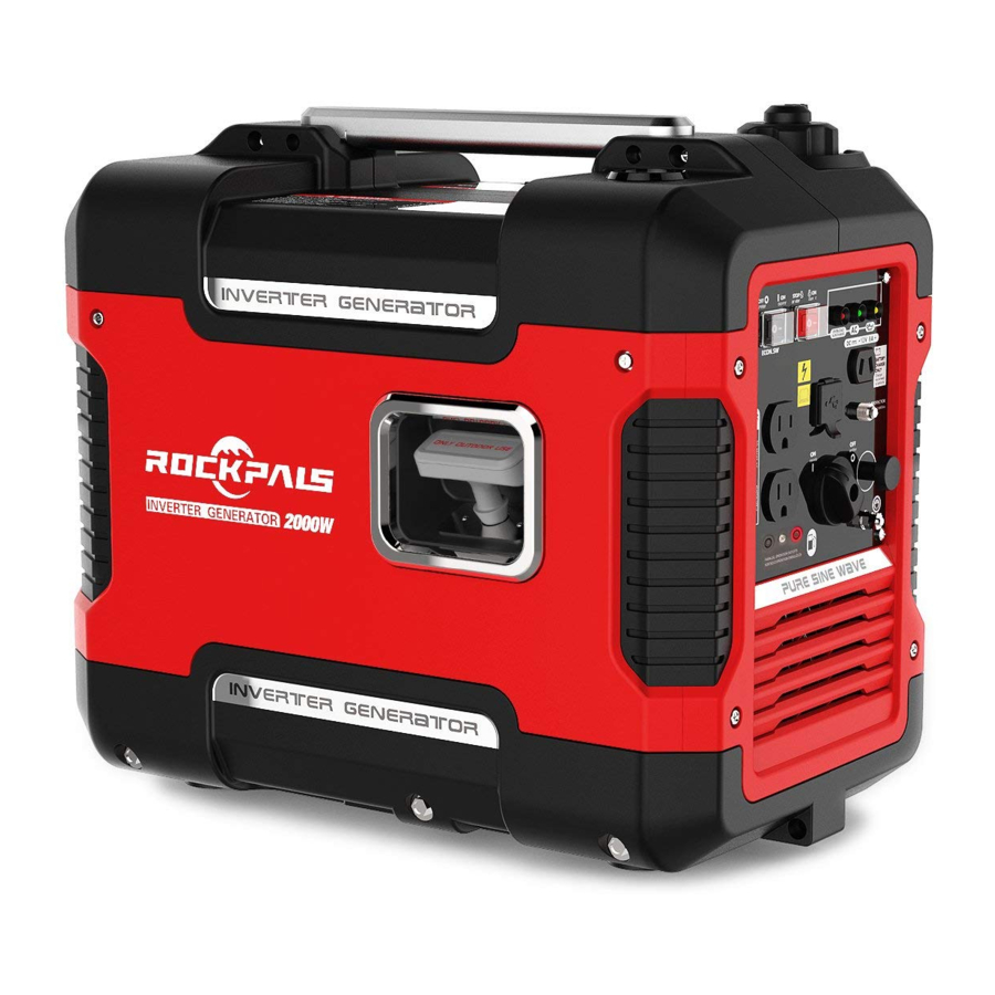
- Page 1 2000W DIGITAL INVERTER GENERATOR WARNING : To reduce the risk of injury, user must read this manual before assembling, opera ng and maintaining this unit, You are responsible for opera ng the product properly & safely. Version: V1.20170921...
-
Page 2: Table Of Contents
WARNING! Read the following instruc�ons before using the product! These instruc�ons below are for your safety. Please read through them thoroughly before use and retain them for future reference. Familiarize yourself with them to reduce hazards like personal injuries and damage to property. TABLE OF CONTENTS Safety Rules.………………….…………………………………………………………………………2 Product Specifica�ons.……….…………………………………………………………………….7... - Page 3 WARNING indicates a hazard, which, move to fresh air RIGHT AWAY. See if not avoided, could result in death or a doctor. You could have carbon monoxide poisoning." serious injury. CAUTION indicates a hazard, which, WARNING This generator if not avoided, might result in minor may emit highly flammable and or moderate injury.
- Page 4 without a qualified electrician. Such the generator by plugging in more connec�ons must comply with local electrical devices than the unit can electrical laws and codes. Failure to handle. comply can create a back-feed, which Do not turn on electrical devices un�l may result in serious injury or death to a�er they are connected to the u�lity workers.
- Page 5 CHARGE ONLY 12V LEAD-ACID BATTERIES. OTHER TYPES OF BATTERIES MAY BURST CAUSING PERSONAL INJURY AND DAMAGE. RISK OF EXPLOSIVE GAS MIXTURE. READ INSTRUCTIONS IN OWNER’S GUIDE BEFORE USING CHARGER. Keep it at least 1m away from inflammable. Fig.4 Never use it indoor. Fig.1 Never smoke when fueling.
- Page 6 CONNECTION TO A HOUSE POWER SUPPLY WARNING: If this generator is used as a supply for a building’s wiring system as a standby, the generator must Fig.10 be installed by a qualified electrician and connected to a transfer switch as a GENERATOR GROUND separately derived system in accordance CIRCUIT...
-
Page 7: Product Specifica�Ons
PRODUCT SPECIFICATIONS Model R2000i Type Inverter Rated Frequency (Hz) Rated Voltage (V) Rated Output Power (KW) Max Output Power (KW) Power Factor Generator Charging Voltage (DC)(V) Charging Current (DC)(A) Overload Protect (DC) Non-fuse Protector USB Port 5V, 1 A&2.1A Phase... -
Page 8: Know Your Inverter Generator
KNOW YOUR INVERTER GENERATOR Fig.12 ① Carrying handle ⑤ Recoil starter ② Fuel tank cap ⑥ Oil filler cap ③ Fuel tank cap air vent knob ⑦ Louver ④ Control panel ⑧ Muffler ACCESSORIES 12V DC Ba�ery charging cable 1 Spark plug socket Oil funnel Screw driver... - Page 9 Control Panel Fig.14 Oil warning light AC receptacle AC pilot light Fuel cock knob Overload indicator light Ground (earth) terminal Engine switch (Red) Choke knob Economy control switch DC protector (Black) USB Port (1A/2.1A) DC receptacle...
- Page 10 on when an overload of a connected CONTROL FUNCTION electrical device is detected, the inverter Engine switch (Red) control unit overheats, or the AC output voltage rises. Then, the AC protector will trip, stopping power genera�on in order to protect the generator and any connected electric devices.
- Page 11 connected to the generator is opera�ng and current above the rated flows. To use this equipment again, turn on DC protector by pressing its bu�on to “ON”. Fig.20 1. “ON”: Direct current is output. Fuel tank cap 2. “OFF”:Direct current is not output. Remove the fuel tank cap by turning it counterclockwise.
-
Page 12: Generator Prepara�On
GENERATOR PREPARATION USING THE GENERATOR FOR THE FIRST TIME The following sec�on describes steps necessary to prepare the generator for use. If a�er reading this sec�on, you are unsure about how to perform any of the steps please call for customer service. Failure to perform these steps properly can damage the generator or shorten its life. - Page 13 3. Remove the dips�ck from the engine. octane ra�ng. Do not mix oil with Insert the oil funnel. (Fig.26) gasoline. To add gasoline, follow these steps: 1. Make sure the generator is on a level surface. 2. Unscrew fuel cap and set aside. NOTE: The fuel cap may be �ght and hard to unscrew.
-
Page 14: Star�Ng The Generator
electrocu�on. Recommended fuel: Unleaded gasoline Fuel tank capacity: Total: 4.0L(1.06 US Ground the generator by �ghtening the gal, 0.88 lmp gal) grounding nut on the front control panel against a grounding wire. A generally • Never use an oil/gasoline mixture. acceptable grounding wire is a No. - Page 15 Generator exhaust contains carbon injury or death to u�lity workers. monoxide (CO). This is a poison gas you -Use a ground fault circuit interrupter cannot see or smell. If you can smell the (GFCI) in highly conduc�ve areas such as generator exhaust, you are breathing CO.
-
Page 16: Stopping The Generator
5. Pull the choke knob fully out. • The ESC unit operates normally a�er the above �me period, while the ECS switch (Black) is “ON”. ECO-MODE IDLE CONTROL SWITCH Fig.36 This generator is equipped with an Eco-Mode Idle Control Switch. Engaging WARNING: The choke is not the switch will automa�cally adjust the required to start a warm engine. -
Page 17: Subsequent Star�Ng Of The Generator
2. Disconnect any electric devices. fuel tank. Drain off the gasoline in the carbure�or. Refer to “Generator Storage “Sec�on. SUBSEQUENT STARTING OF Fig.40 3. Turn the engine switch (Red) to THE GENERATOR “STOP” . PRE-OPERATION CHECK WARNING: If any item in the Pre-opera�on check is Fig.41 not working properly, have it inspected 4. - Page 18 should be checked before each use to ensure that the engine crankcase contains WARNING : This generator sufficient lubricant. may emit highly flammable and To check or add oil, follow these steps: explosive gasoline vapors, which can cause severe bums or even death if 1.
-
Page 19: Using The Generator
generator shall be connected to a Step 3 - GROUND THE transfer switch that switches all GENERATOR conductors other than the equipment grounding conductor. The frame of the WARNING: Failure to generator shall be connected to an properly ground the generator can approved grounding electrode. - Page 20 Surge (circuit breakers). (Running) Wa age Wa age NOTE: Check the wa age on the electrical device . Once the electrical R2000i 1800 2000 devices that will be powered by the Generator Wa age Fig.46 - generator have been determined,...
- Page 21 when the temperature, the humidity and Wire 300 200 150 Gauge wire the al�tude are higher than standard 375 200 125 100 atmospheric condi�ons. wire 250 125 100 50 Addi�onally, the load must be reduced wire when using in a confined areas, as Fig.47 generator cooling is affected.
- Page 22 the end of ba�ery charging. BATTERY CHARGING • Measure the specific gravity of NOTE: electrolyte to determine if the ba�ery is • The generator DC rated voltage is 12V. fully charged. At full charge, the • Start the engine first, and then connect electrolyte specific gravity is between the generator to the ba�ery for charging.
-
Page 23: Maintenance
Rated Power output CAUTION factor power • Do not overload. The total load of all electrical appliances must not ≤1,600W exceed the supply range of the generator . Overloading will damage the generator. 0.8-0.95 ≤1,280W • When supplying precision equipment, electronic controllers, PC, Electronic 0.4-0.75 computers, microcomputer based... - Page 24 Each 8 First Every 3 Every 6 Ever Every hours months months Items Frequency nece hours .or 50 or 100 year hours ssary daily hours hours Check-refill √ Engine oil replace √ *√ *√ *√ Reduc�on Oil level √ gear oil check replace √...
- Page 25 �me (hour), the one which comes first surface. should govern. 2. Open access panel. Clean around oil fill. • If you have missed the scheduled �me Remove dips�ck and wipe the dips�ck to maintain your engine, do it as soon as with a clean rag.
- Page 26 crankcase. The engine is equipped with Replace the crankcase with oil, follow these steps: a low oil pressure sensor and will not start if the amount of oil is insufficient. 1. Place the generator on elevated pla�orm such as table or desk, and warm up the engine for several minutes.
- Page 27 WARNING: Fuel is highly flammable and poisonous. see “SAFETY INFORMATION” sec�on carefully. CAUTION Immediately wipe off spilled fuel with a Fig.59 clean, dry, so� cloth, since fuel may 7. Turn the engine switch to “STOP”. deteriorate painted surfaces or plas�c parts.
- Page 28 1. Remove the cover ① 2. Remove spark plug boot②. Be careful not to tear insula�on or wire and Insert the tool ④ through the hole from the outside of the cover. Fig.64 Standard Spark Plug: E6TC/E6RTC Spark Plug Gap: 0.6-0.7mm (0.024-0.028in) 6.
- Page 29 Air filter squeezing it. This could cause it to tear. 6. Oil the foam element and squeeze out Rou�ne maintenance of the air cleaner excess oil. helps maintain proper airflow to the 7. Wipe off excessive oil from the air carbure�or.
- Page 30 muffler screen and spark arrester using a MUFFLER SCREEN AND SPARK wire brush. ARRESTER CAUTION When cleaning, use the wire brush WARNING lightly to avoid damaging or scratching The engine and muffler will be very hot of muffler screen and spark arrester. a�er the engine has been run.
-
Page 31: Storage
4. Install the fuel tank cap. NOTE: Be sure the fuel tank cap is �ghtened securely. Fig.75 3. Take out the fuel filter ⑥. Fig.76 4. Clean the filter with gasoline. 5. Dry the filter and put it back into tank. 6. - Page 32 ENGINE Drain the fuel tank • Drain the carburettor • Change oi • Do not obstruct any ventilation • openings. Keep the generator in a cool dry area. •...
-
Page 33: Troubleshoo�Ng
TROUBLESHOOTING IMPORTANT: If trouble persists, please call our customer service center. Problem Cause Solu�on Engine switch in “OFF” posi�on Set engine switch to “ON” posi�on. Engine Pull the Choke knob fully out Press the choke knob fully in will not when warm start start Engine is filled with... - Page 34 Generator Bad connec�ng wires/cables. If using an extension cord, try a different one. runs but Bad electrical device Try connec�ng a different device does not connected to generator. support all Generator is overloaded, Perform these steps: 1. Turn off all electrical electrical Overload light is on devices.
-
Page 35: Wiring Diagram
WIRING DIAGRAM... -
Page 36: A112001 Exploded View & Part List
A112001 EXPLODED VIEW AND PART LIST FIG.1 Engine (E00) Qty/ Refe# Descrip�on Qty/pc Stock# Refe# Descrip�on Stock# A112001-1-1 Muffler A112001-1-4 Engine Cover Tapping A112001-1-2 A112001-1-5 Fuel Pipe Screw A112001-1-3 A112001-1-6 Flange Bolt FIG.2 Tank, Fuel (F01) Qty/ Qty/ Refe# Descrip�on Stock# Refe# Descrip�on... - Page 37 FIG.3 Muffler Cover (F61) Qty/ Refe# Descrip�on Stock# Refe# Descrip�on Qty/pc Stock# Muffler Cover A112001-3-1 Clip Nut A112001-3-5 Support Cross Pan Alternator A112001-3-2 A112001-3-6 Bolts Cover Tapping Muffle Cover A112001-3-3 A112001-3-7 Screw Tapping 5# Rubber A112001-3-4 A112001-3-8 Screw Parts FIG.4 Cover and Panel(F61) Qty/ Refe# Descrip�on...
- Page 38 Rubber Back Panel A112001-4-3 4-12 A112001-4-12 Parts M6x20 Flange Front A112001-4-4 4-13 A112001-4-13 Bolt Housing M6x10 Flange Viewing A112001-4-5 4-14 A112001-4-14 Bolt Mirror 4# Rubber A112001-4-6 4-15 Front Board A112001-4-15 Parts M5 Nut A112001-4-7 4-16 Recoil Baffle A112001-4-16 Bushing A112001-4-8 4-17 Frame A112001-4-17...
- Page 39 FIG.6 Control Panel (F62) Qty/ Qty/ Refe# Descrip�on Stock# Refe# Descrip�on Stock# Tapping Cross Bolt A112001-6-1 A112001-6-9 Screw Fuel Pipe A112001-6-2 6-10 Socket A112001-6-10 Fuel Switch A112001-6-3 6-11 Switch A112001-6-11 Shim A112001-6-4 6-12 Socket A112001-6-12 Panel DC Charger A112001-6-5 6-13 A112001-6-13 Housing Socket...
- Page 40 FIG.7 Rotor/Stator (F63) Refe Qty/ Qty/p Descrip�on Stock# Refe# Descrip�on Stock# Flange Flange Bolt A112001-7-1 A112001-7-6 Bolt Alternator A112001-7-2 A112001-7-7 Cover Flange Stator ASSY A112001-7-3 A112001-7-8 Bolt Rotor ASSY A112001-7-4 Flange Nut A112001-7-9 A112001-7-1 A112001-7-5 7-10 Alternator...
-
Page 41: A112002 Exploded View & Part List
A112002 EXPLODED VIEW AND PART LIST FIG.1 Engine (E00) Qty/ Refe# Descrip�on Qty/pc Stock# Refe# Descrip�on Stock# A112002-1-1 Muffler A112002-1-4 Engine Cover Tapping A112002-1-2 A112002-1-5 Fuel Pipe Screw A112002-1-3 A112002-1-6 Flange Bolt FIG.2 Tank, Fuel (F01) Qty/ Qty/ Refe# Descrip�on Stock# Refe# Descrip�on... - Page 42 FIG.3 Muffler Cover (F61) Qty/ Refe# Descrip�on Stock# Refe# Descrip�on Qty/pc Stock# Muffler Cover A112002-3-1 Clip Nut A112002-3-5 Support Cross Pan Alternator A112002-3-2 A112002-3-6 Bolts Cover Tapping Muffle Cover A112002-3-3 A112002-3-7 Screw Tapping 5# Rubber A112002-3-4 A112002-3-8 Screw Parts FIG.4 Cover and Panel(F61) Qty/ Refe# Descrip�on...
- Page 43 Rubber Back Panel A112002-4-3 4-12 A112002-4-12 Parts M6x20 Flange Front A112002-4-4 4-13 A112002-4-13 Bolt Housing M6x10 Flange Viewing A112002-4-5 4-14 A112002-4-14 Bolt Mirror 4# Rubber A112002-4-6 4-15 Front Board A112002-4-15 Parts M5 Nut A112002-4-7 4-16 Recoil Baffle A112002-4-16 Bushing A112002-4-8 4-17 Frame A112002-4-17...
- Page 44 FIG.6 Control Panel (F62) Qty/ Qty/ Refe# Descrip�on Stock# Refe# Descrip�on Stock# Tapping Cross Bolt A112002-6-1 A112002-6-9 Screw Fuel Pipe A112002-6-2 6-10 Socket A112002-6-10 Fuel Switch A112002-6-3 6-11 Switch A112002-6-11 Shim A112002-6-4 6-12 Socket A112002-6-12 Panel DC Charger A112002-6-5 6-13 A112002-6-13 Housing Socket...
- Page 45 Flange Flange Bolt A112002-7-1 A112002-7-6 Bolt Alternator A112002-7-2 A112002-7-7 Cover Flange Stator ASSY A112002-7-3 A112002-7-8 Bolt Rotor ASSY A112002-7-4 Flange Nut A112002-7-9 A112002-7-1 A112002-7-5 7-10 Alternator E-mail: brand@rockpals.com Phone: (877) 756-8666 Mon-Fri 9 AM-5 PM (PST) Website: www.rockpals.com Facebook: @RockpalsOfficials...
Need help?
Do you have a question about the R2000i and is the answer not in the manual?
Questions and answers