Advertisement
Quick Links
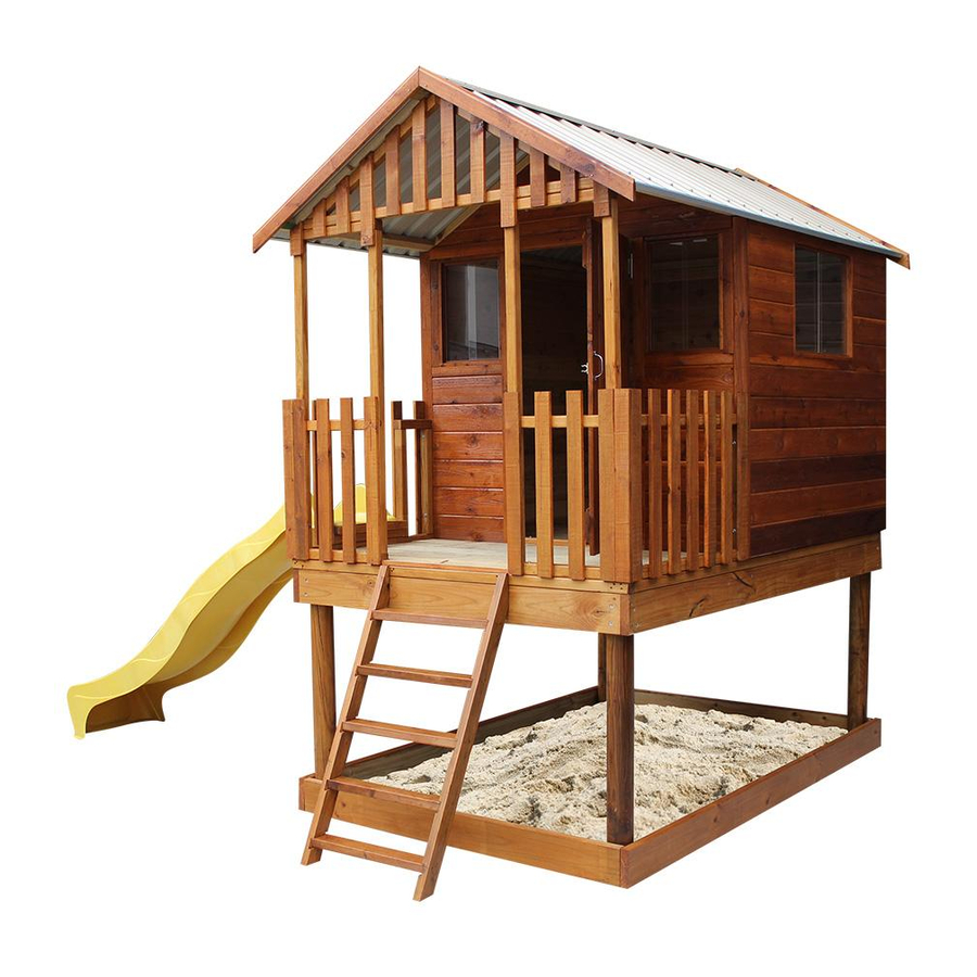
STILLA
ASSEMBLY INSTRUCTIONS
'Hideout Tower'
S2031
Every part needed to construct your cubby is included inside the pack; cedar
panels, doors, windows, hardware kits & roof sheeting. Please ensure you fully
unpack all the parts & check against the parts checklist before contacting
customer service about anything you believe may be missing. Thank-you!
Advertisement

Related Manuals for STILLA Hideout Tower

Summary of Contents for STILLA Hideout Tower
- Page 1 STILLA ASSEMBLY INSTRUCTIONS ‘Hideout Tower’ S2031 Every part needed to construct your cubby is included inside the pack; cedar panels, doors, windows, hardware kits & roof sheeting. Please ensure you fully unpack all the parts & check against the parts checklist before contacting...
- Page 2 Caution Please be careful when handling all components, some parts have sharp metal edges. Always wear work gloves, eye protection and long sleeves when assembling or maintaining your Hideout. Tools required for assembly • Level • Batten drive • Drill •...
- Page 3 HIDEOUT TOWER PARTS CHECKLIST Part Code Part Description Back Panel Front Panel Side Panel Window Panel 5ft Front Gable 5ft Back Gable 5ft Verandah Gable Side Railing Front Verandah Railing Roof Rafters 780mm Roof Sheeting 6 &2 Double Pans 980mm 6 &...
- Page 4 Double joist – 2330x140x35 with 42mm joined 100BS 100mm Batten Screw 1.0 - ASSEMBLY – ELEVATED FLOOR KIT Fasten through EP into DJ using 3x100BS per join. Fasten through EP into SJ using 2x100BS per join. FRONT OF HIDEOUT TOWER P a g e...
- Page 5 STEP 1.1 FLOOR FOUNDATIONS 1.1 - ASSEMBLY – FLOOR FOUNDATION Place floor in desired install location and mark the 4 corners on ground surface. Remove floor and dig holes in position shown. (500mm deep holes). Ensure square. Mark holes holes P a g e...
- Page 6 STEP 1.2 ATTACHING LOGS TO FLOOR FRAME 1.2 - ASSEMBLY PARTS – ATTACHING LOG’S TO FLOOR FRAMES PART CODE QTY DESCRIPTION 100BS 100mm Batten screw 1.2 - ASSEMBLY – ATTACHING LOG’S TO FLOOR FRAMES Place floor frame on flat surface and fasten logs in place as shown in diagram using 4 x 100BS per log/per corner.
- Page 7 STEP 1.4 ELEVATED FLOOR KIT 1.4 - ASSEMBLY PARTS – ELEVATED FLOOR KIT PART CODE QTY DESCRIPTION Floor board 50PS 50mm Phillips screw 1.4 - ASSEMBLY – ELEVATED FLOOR KIT Place floor boards on floor and fasten to floor frame using 12x50PS per sheet. Floor boards sit in 36mm from sides &...
-
Page 8: Ladder Installation
STEP 1.5 LADDER INSTALLATION 1.5 - ASSEMBLY PARTS – LADDER INSTALLATION PART CODE QTY DESCRIPTION Ladder 65HHS 65mm Hex head screw 1.5 - ASSEMBLY – LADDER INSTALLATION Holding ladder in position, fasten to floor using 2 x 65HHS. STEP 2.0 WALL ASSEMBLY Ensure tongue on VJ Cedar Cladding is facing upwards. - Page 9 STEP 2.1 WALL ASSEMBLY 2.1 - ASSEMBLY PARTS – WALL ASSEMBLY PART CODE QTY DESCRIPTION 1500mm Window panel - peel protective cover off Perspex windows 65HHS 65mm Hex head screw 2.1 - ASSEMBLY – WALL ASSEMBLY Screw through BP into WP at top and bottom, holding studs flush on the inside. STEP 2.2 WALL ASSEMBLY 2.2 - ASSEMBLY PARTS –...
-
Page 10: Wall Assembly
STEP 2.3 WALL ASSEMBLY 2.3 - ASSEMBLY PARTS – FASTEN TO FLOOR PART CODE QTY DESCRIPTION 65HHS 65mm Hex head screw 2.3 - ASSEMBLY – FASTEN TO FLOOR Position cubby with wall cladding overhanging floor on sides and back. Screw through bottom plate on wall panels. STEP 2.4 VERANDAH RAILING ASSEMBLY 2.4 - ASSEMBLY PARTS –... - Page 11 STEP 2.5 VERANDAH RAILING ASSEMBLY 2.5 - ASSEMBLY PARTS – VERANDAH RAILING ASSEMBLY PART CODE QTY DESCRIPTION Front verandah railing 2.5 - ASSEMBLY – VERANDAH RAILING ASSEMBLY Hold FR in position screw through FR into SR using 2 x 65HHS. Fasten FR to floor using 1 x 65HHS through bottom plate –...
- Page 12 STEP 3.0 GABLE ASSEMBLY 3.0 - ASSEMBLY PARTS – GABLE ASSEMBLY PART CODE QTY DESCRIPTION Verandah gable 65HHS 65mm Hex head screw 3.0 - ASSEMBLY – GABLE ASSEMBLY Holding veranda gable (VG) in position, fasten up through front panels using 2 x 65HHS either side.
- Page 13 STEP 3.1 GABLE ASSEMBLY 3.1 - ASSEMBLY PARTS – GABLE ASSEMBLY PART CODE QTY DESCRIPTION Back gable Front gable 65HHS 65mm Hex head screw 3.1 - ASSEMBLY – GABLE ASSEMBLY Holding gables (FG & BG) in position fasten up through Front and Back panels to secure. 12 | P a g e...
- Page 14 STEP 3.2 VERANDAH FLOOR 3.2 - ASSEMBLY PARTS – VERANDAH FLOOR PART CODE QTY DESCRIPTION Verandah Floor board 40mm Nail Door Step 3.2 - ASSEMBLY – VERANDAH FLOOR Lay verandah floor boards on verandah frame of cubby. Evenly space floor boards. Using 8x40N per board, fasten into SJ’s &...
-
Page 15: Roof Assembly
STEP 3.3 ROOF ASSEMBLY 3.3 - ASSEMBLY PARTS – ROOF ASSEMBLY PART CODE QTY DESCRIPTION Bottom batten Top batten Rafter 100BS 100mm Batten screw 3.3 - ASSEMBLY – ROOF ASSEMBLY Slide rafters (R) into checked out sections in battens (BB & TB). Fasten through BB & TB into R using 1 x 100BS per join. - Page 16 STEP 3.4 ROOF ASSEMBLY 3.4 - ASSEMBLY PARTS – ROOF ASSEMBLY PART CODE QTY DESCRIPTION 980mm Paper bark roof sheet 40RS 40mm Roof screw 25RS 25mm Roof screw 3.4 - ASSEMBLY – ROOF ASSEMBLY Lay roof on a hard surface. Position 1 roof sheet at each end (RS) flush at top and flush with end of roof battens.
- Page 17 STEP 3.5 ROOF ASSEMBLY 3.5 - ASSEMBLY PARTS – ROOF ASSEMBLY PART CODE QTY DESCRIPTION 980mm Roof sheet 40RS 40mm Roof screw 25RS 25mm Roof screw 3.5 - ASSEMBLY – ROOF ASSEMBLY Complete laying roof sheeting out on frame. Fasten roof sheets to battens in sequence shown.
- Page 18 STEP 3.6 ROOF ASSEMBLY 3.6 - ASSEMBLY PARTS – ROOF ASSEMBLY PART CODE QTY DESCRIPTION 40RS 40mm Roof screw 25RS 25mm Roof screw 3.6 - ASSEMBLY – ROOF ASSEMBLY Complete screwing roof off at top. 1 x 25RS in pan beside every rib. Once top complete screw bottom off using 1 x 40RS in every rib.
- Page 19 STEP 3.7 ROOF ASSEMBLY 3.7 - ASSEMBLY PARTS – ROOF ASSEMBLY PART CODE QTY DESCRIPTION 2565mm Channel Self-tapping screw 3.7 - ASSEMBLY – ROOF ASSEMBLY Fasten capping C to roof using 5 x ST. Bent up edge at top. (TOP) 18 | P a g e...
-
Page 20: Roof Installation
STEP 3.7 ROOF INSTALLATION 3.7 - ASSEMBLY PARTS – ROOF INSTALLATION PART CODE QTY DESCRIPTION Completed rooves 3.7 - ASSEMBLY – ROOF INSTALLATION Slide roof panel into position with rafters flush with gables on the inside (see diagram). Fasten up through all 3 gables into roof panel. 2 x 65HHS into veranda gable & 1 x 65HHS into cubby gables screw up through cubby side walls using 2 x 65HHS per side. - Page 21 STEP 4.1 RIDGE CAP ASSEMBLY 4.1 - ASSEMBLY PARTS – RIDGE CAP ASSEMBLY PART CODE QTY DESCRIPTION Ridge cap 40RS 40mm Roof screw 4.1 - ASSEMBLY – RIDGE CAP ASSEMBLY Slide ridge caps (RC) into position. Screw through ridge caps, through 2 rib in and into batten.
- Page 22 STEP 5.0 HANGING DOOR 5.0 - ASSEMBLY PARTS –HANGING DOOR PART CODE QTY DESCRIPTION Hinge Screw Hinge Door Handle 5.0 - ASSEMBLY – HANGING DOOR Screw hinges to door centred over brace on back using HS. Holding door centre of opening, fasten to cubby front panel using HS. Screw door handle in position shown.
- Page 23 STEP 5.1 DOOR CLIP ASSEMBLY 5.1 - ASSEMBLY PARTS – DOOR CLIP ASSEMBLY PART CODE QTY DESCRIPTION Door Clip 50PS 50mm Phillips screw 5.1 - ASSEMBLY – DOOR CLIP ASSEMBLY Fasten clip to back of door behind door handle using 15mm screw provided. Holding door in closed position with hasp in clip, fasten to cubby wall frame using 1x50PS.
-
Page 24: Product Maintenance
TO REGISTER YOUR WARRANTY Thank-you for purchasing a STILLA product. To register your 10 year product warranty, please go to www.stilla.com.au/warranty and complete the online form. We recommend that you complete this step once you have finished installing your product. - Page 25 24 | P a g e...
- Page 26 25 | P a g e...
- Page 27 26 | P a g e...
- Page 28 SHOW US YOUR CUBBY We would love to see a photo of your STILLA product installed in your backyard. Please upload this image when completing the warranty registration. Alternatively, you can send the photos by email to sales@stilla.com.au. If you require any assistance, please feel free to call or email.
Need help?
Do you have a question about the Hideout Tower and is the answer not in the manual?
Questions and answers