Download Print this page
Nexxt Professional Series User Manual

Nexxt Professional Series User Manual

Hide thumbs Also See for Professional Series:

Advertisement

Quick Links

Semi-knocked down
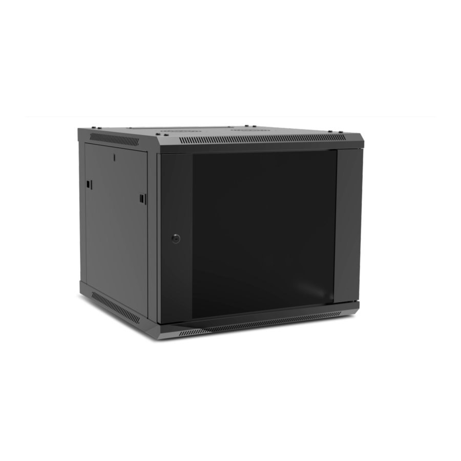
fixed wall-mount enclosure
NPC-F9U64B
NPC-F12U64B
NPC-F15U64B
NPC-F18U64B
ProfessionalSeries
NPC-F6U64B
NPC-F12U66B
NPC-F6U66B
NPC-F15U66B
NPC-F9U66B
NPC-F18U66B

Advertisement

loading
Need help?

Need help?

Do you have a question about the Professional Series and is the answer not in the manual?

Questions and answers

Summary of Contents for Nexxt Professional Series

  • Page 1 Semi-knocked down fixed wall-mount enclosure NPC-F9U64B NPC-F12U64B NPC-F6U64B NPC-F12U66B NPC-F15U64B NPC-F6U66B NPC-F15U66B NPC-F18U64B NPC-F9U66B NPC-F18U66B ProfessionalSeries...
  • Page 2: Important Safety Information

    User manual Nexxt solutions does not warrant against damage caused by the use of any Nexxt Solutions enclosures for any purposes other than those for which it was designed or damage caused by unauthorized attachments or modifications, and is not responsible...
  • Page 3: Preliminary Steps

    2.Preliminary steps • Prior to installing this product, you must read all instructions thoroughly. Right support frame • Keep these instructions handy in an easily accessible location for future reference. • A clean, flat, level, protected floor area should be provided for cabinet assembly to prevent damage to parts.
  • Page 4 Hardware kit Phase Required parts Steps M8x12mm hexagon socket head screw Bottom panel subassembly 1. Align the left support frame with the front and back corners of the M8 flange nut bottom panel. The section with the grille must be facing the front, and the cable entry plate should be facing the back.
  • Page 5 3. Insert the M4 self-tapping screws onto the front end of the 4. Repeat instructions 1 though 3 to attach the right support frame bottom panel subassembly, as shown in image below. to the bottom panel. Note: do not fully-tighten the screws at this point. Cable entry plate (2) M8x12 hexagon screws (8) 5.
  • Page 6 Installing horizontal brackets Vertical rails installation 1. Position the left vertical rails between the front and rear frames. 1. On the left side of the frame, position the left L-shape bracket between the front and rear sections of the enclosure. 2.
  • Page 7 Lateral panels 2. Push the panel forward into the frame and make sure all mounting holes are aligned. 1. Next, identify the 2 side panels. Both are identical for this model. 3. Using the M4 self-tapping screws, secure the rear panel to the M4x8mm self-tapping screws (8) enclosure.
  • Page 8 Grounding connection 1. Connect the first grounding cable to the door using the provided Notes hardware. M4x8mm self-tapping screws (2) Grounding wires (3 sets) 2. Likewise, connect the second grounding cable to the side panel using the hardware provided. 3. Using the self-tapping screw bind both grounding cables to the closest mounting hole on the right side horizontal beam.