Table of Contents
Advertisement
Advertisement
Chapters
Table of Contents

Subscribe to Our Youtube Channel
Related Manuals for Wellington SCS Connect

Summary of Contents for Wellington SCS Connect
- Page 1 TECHNICAL USER MANUAL CONNECT...
- Page 2 2016 Wellington Drive Technologies Limited © 21 Arrenway Drive, Rosedale, Auckland 0632, New Zealand PO Box 302-533, North Harbour, Auckland 0751, New Zealand Tel.: + 64 9 477 4500, Fax: + 64 9 479 5540, E-mail: info@wdtl.com Website: www.wdtl.com...
-
Page 3: Table Of Contents
TABLE OF CONTENTS Quick Read TECHNICAL USER MANUAL PARAMETERS Normal Mode (nrL) TABLE OF CONTENTS WARNINGS! Transition 1 Mode (tn1) INTRODUCTION Transition 2 Mode (tn2) PRODUCT DESCRIPTION Standby Mode (SdY) Front Display Panel Transition 3 Mode (tn3) Rear Connector Panel Defrost Mode (dEF) Installation Diagrams Door Menu (dor) Wiring Diagrams Compressor Menu (CoP) Operating Cycle Supply Menu (nrG) START UP SEQUENCE... -
Page 4: Warnings
Connect. Do not open the Exposure to impacts, either in operation, installation, housing. Warning! Risk of transportation, or storage, may damage electronic circuits electrocution. and housing components, leading to premature failure, and may cause the SCS Connect controller to become unsafe. Any impact which causes visual damage to the controller casing will invalidate the warantee. No serviceable parts; There are no serviceable parts inside the SCS Connect controller. Do not open the housing, except for the rear cover, as described in the “Description and Installation” section of... - Page 5 The following parts are considered to be subject to normal wear and tear, and as such are not covered by warranty • Scratches and other visual damage to front panel Voltages; The SCS Connect controller must only be connected to Do not connect the SCS power supplies which comply with the acceptable voltage Connect controller to the ranges specified in the “Technical Specification” section of incorrect voltage supply.
- Page 6 Quick Read Warnings - cont Fit for purpose; The SCS Connect controller must only be used for the The SCS Connect controller purpose and functions described in this manual. While must only be used for the Wellington Drive Technologies Limited may provide purposes described in this technical support on suitable applications and configuration manual. of the SCS Connect controller (where such a relationship...
-
Page 7: Introduction
† Wireless data logging and Technicians full wireless access to data logging and diagnostic diagnostic control control. † Compact size The SCS Connect controller’s housing meets industry benchmarks for compact size and exceeds benchmarks for sealing at the † Sealed front face. The appearance of the SCS Connect controller can be customized to suit the brand requirements of end customers. † Customized branding available PD0006 v3.0 – 6 Dec 2017... -
Page 8: Product Description
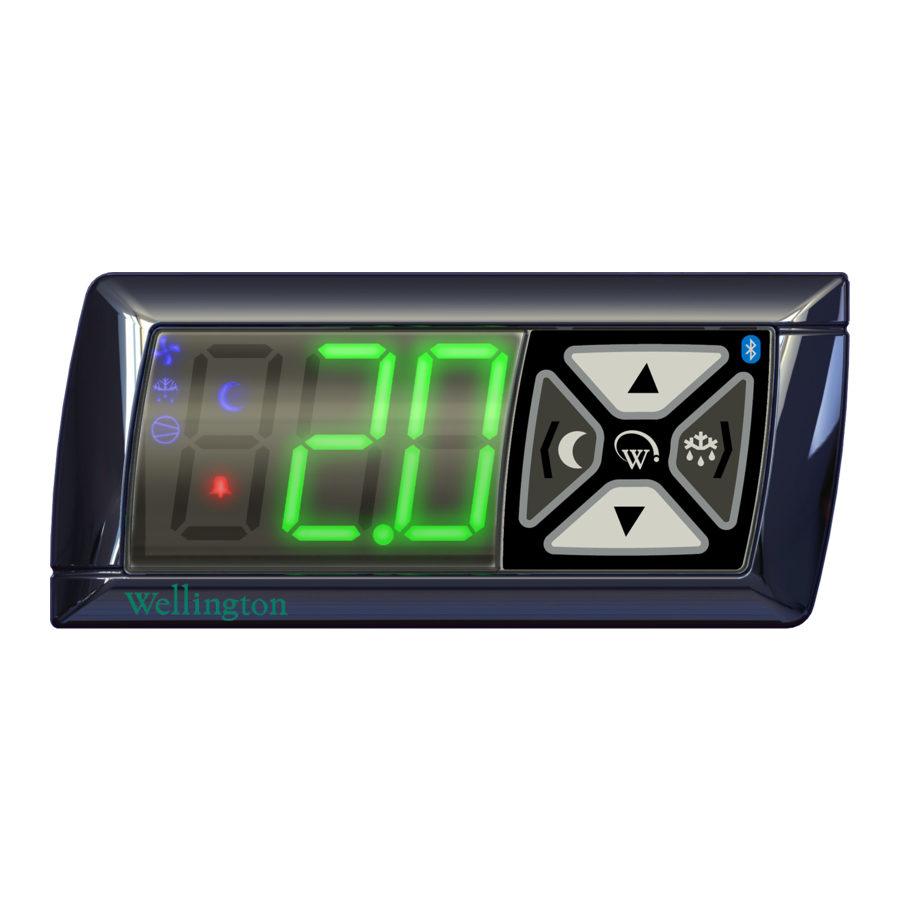
PRODUCT DESCRIPTION Quick Read The SCS Connect controller consists of three main groups of † Three main feature features: locations: The Front Display Panel with the user interface controls. † Front Display Panel The Rear Connector Panel where the input and output † Rear Connector Panel cables are connected. -
Page 9: Rear Connector Panel
Product Description Rear Connector Panel AD5 AD4 AD2 AD1 Switched 8 (8)Arms, Compressor* 90-240Vac o/p Sensor i/p* Digital 0-5V i/p Switched o/p* Analog NTC i/p Switched Relay* 3 (3) Arms 90-240Vac o/p Digital 0-5V i/p Sensor i/p* Switched 0.4Arms Analog NTC i/p Switch 1* Switched o/p* 90-240Vac o/p 5V 100mA o/p Digital 0-5V i/p Switched 0.4Arms... -
Page 10: Installation Diagrams
Installation Installation Diagrams INSTALLATION PROCEDURE STEP 1 Clip on the Front Fascia Panel. 71.5mm +-0.5mm Cut a rectangular aperture in the Mounting Panel which measures 71.5mm wide by 29.5mm high. Insert the SCS™ Connect into the hole. IMPORTANT: The maximum permitted mounting panel 29.5mm thickness is 9mm. Ensure there +-0.5mm are no obstructions 7mm to the left and right of the hole, and 4mm above and below. This will ensure there is clearance with the Front Fascia. - Page 11 Installation Overall Dimensions 81.2 76.5 16.5 PD0006 v3.0 – 6 Dec 2017...
-
Page 12: Wiring Diagrams
(P) L Brown P Optional customer defined item; Blue N AC Lights, Defrost Brown Heater, etc. Max Load 5A Blue N MAINS CONNECTIONS Warning! Risk of Electrocution *Alternative connection method for Wellington Variable Speed Motors. PD0006 v3.0 – 6 Dec 2017... -
Page 13: Operating Cycle
Product Operation Operating Cycle PD0006 v3.0 – 6 Dec 2017... - Page 14 Product Operation Standby Refrigeration Cycles 24 hours STANDARD Pulldown Time (Pdt) DAILY CYCLE Inactivity Wait Time - Normal Mode (Ytn) Activity detected Inactivity Wait Time - Normal Mode (Ytn) Maximum Standby Time (Sbt) Activity When in Non-Perishable Mode, the SCS™ Connect enters Standby Mode at night to save energy. At the start of each day, it leaves Standby Mode and commences a Pulldown. The start of the Pulldown is timed to ensure that the Operational Set Point (SP) is reached before the first customer Activity is expected. When the Operational Set Point (SP) is reached the SCS™ Connect enters Normal Mode. 24 hours ADVANCED DAILY CYCLE...
- Page 15 Product Operation Standby Refrigeration Cycles 24 hours CYCLE WHEN OUTLET CLOSED Pulldown Time Activity (Pdt) detected Inactivity Wait Time - Normal Mode (Ytn) Inactivity Inactivity Wait Time Wait Time - Standby - Standby Maximum Hold (yth) Hold (yth) Standby Time (Sbt) Activity Outlet re-opens Inactivity Wait Time -...
- Page 16 Product Operation Standby Refrigeration Cycles DOOR OPEN STATE CHANGES Normal Transition 2 Standby Transition 1 Transition 3 and Standby Hold Activity If the cooler is in Normal mode and an activity is seen, the “Inactivity Wait Timer - Normal Mode” will be reset. If the cooler is in Transition 1 Mode and an activity is seen, the cooler will move back to Normal Mode, and the “Inactivity Wait Timer - Normal Mode” will be reset. If the cooler is in Transition 2 Mode and an activity is seen, the cooler will move back to Transition 1 Mode, and the “Inactivity Wait Timer - Transition 1” will be reset. If the cooler is in Standby Mode and an activity is seen, the cooler will move back to Transition 2 Mode, and the “Inactivity Wait Timer - Transition 2” will be reset. If the cooler is in Transition 3 Mode or Standby Hold Mode and an activity is seen, the cooler will move back to Normal Mode, and the “Inactivity Wait Timer - Normal Mode” will be reset. PD0006 v3.0 – 6 Dec 2017...
-
Page 17: Start Up Sequence
START UP SEQUENCE Start-Up Sequence Quick Read Power cycling the SCS™ Connect initiates the start up † Step 1: Displays “SCS”. sequence, which goes through the following steps: † Step 2: Displays the Step 1. Firmware Version. Displays “SCS”. † Step 3: Displays the Step2. Parameter Set Name. The current Firmware Version is briefly displayed. This is a 6 (not yet implemented). digit number. The first 3 digits are displayed for 2 seconds, then the remaining 3 digits for 2 seconds. † Step 4: Cycles through a self-test routine. -
Page 18: Front Panel User Interface
FRONT PANEL USER INTERFACE User Mode Quick Read These are the essential functions that retail staff can control: † Controls the essential end-user functions; Lights, † Manually toggle the Lights on and off. Transition Mode, Defrost Mode, Set Point Temperature. † Manually toggle Standby Mode on and off. † A PIN code is required to † Manually initiate a Defrost. enter the Service Mode menus. -
Page 19: Service Mode
There are 5 categories main Service Mode catagories: Five main Categories to select from: † Parameters: For details on configuring parameters please refer to page 27. † Parameters † Reset*: Returns the SCS Connect controller back to † Reset Factory or Default Settings. † Manual Test † Manual Test*: Allows Service Staff to inspect input values from sensors and check the effects of output † Statistics adjustments to peripherals, and to run preset test routines. - Page 20 Parameters Flow Chart SERVICE MODE UI - cont Reset Flow Chart Manual Test Flow Chart Return to Enter Service User Mode Mode PIN page 21 Next Category Up Display Exit Categories Category List Next Category Down Enter Selected Category Store Changes Next If Changes Menu Up...
- Page 21 Statistics Flow Chart SERVICE MODE UI - cont About Flow Chart Return to Enter Service User Mode Mode PIN page 22 Next Category Up Display Exit Categories Category List Next Category Down Back To Enter Category Selected List Category Next Menu Up Display Menu List Next Menu...
-
Page 22: Graphical User Interfaces
GRAPHICAL USER INTERFACES Quick Read The Wellington SCS Connect controller App provides a wireless connection to the SCS Connect controller from mobile devices † Wellington SCS fitted with Bluetooth® LE. This gives users and technicians an Connect controller App: unprecedented level of visibility, control and diagnostic tools † Bluetooth LE compliant. to optimise the controller’s performance and to troubleshoot ® any problems. The following guide provides an overview of † Wireless diagnostics and the app and its capabilities. control. Note: Screen shots shown are indicative only. Different devices have different screen ratios, sizes and resolutions. The... -
Page 23: Authentication
MOBILE GUI - cont Authentication Step 1 Step 2 Download and install the Connect Field When you first run “Connect Field”, you will app from Google Play (Search for “scs be requested to enter an activation code. wellington” to find it) Contact your User Manager or Wellington to receive your activation code (You must be connected to the internet at the time of activation). Note: Your activation code is unique to you, and should NEVER be shared with anyone else, as it determines your personal access level for the app. The same code will give you access to all SCS apps you are authorised to use. Step 3 Step 4 Your 9-digit touch panel... -
Page 24: Connecting To A Device
MOBILE GUI - cont Connecting to a Device Note: If the Bluetooth™ logo on the top right of the SCS™ Connect button panel is lit, then the Bluetooth™ signal is broadcasting and the device should be visible. This logo will start flashing when connected to a device Select a device to connect to from the list of visable devices Note: This list is filtered by your activation permissions, so devices you are not authorised to connect to will not be displayed. -
Page 25: Parameter Editing
MOBILE GUI - cont Parameter Editing Step 1 Step 2 Select “EDIT PARAMETERS” from the Main Select the parameter Catagory you want to menu view Pull down box Step 3 Step 4 to select non- numerical values Text box to enter numerical values directly Slider to Reset to factory select default settings Numerical values Apply the change to... -
Page 26: Parameters
DESKTOP GUI Parameter Editing - Desktop The Desktop App is intended for OEM’s and manufacturers. It supports easy creation, checking and saving of parameter files for Lab and Production use: • Requires a Blue-Giga USB dongle to support BT-LE Due to the poor handling of Bluetooth LE by Windows, use of the desktop app on Windows computers requires an external Bluetooth device (“dongle”). The supported dongle is Blue-Giga model BLED112, available from Blue-Giga stockists or from Wellington. • Uses the same activation code as for all other apps • Connects to the controller in the same way as the mobile app • Basic 4-screen interface (no hidden menus) - Diagnostics - Edit Parameters - Asset Info... -
Page 27: Normal Mode (Nrl)
PARAMETERS Quick Read The SCS Connect parameters have been grouped together as † A full alphabetical follows: summary list of all available parameters can Normal Mode (nrL) page 27. be found on Pg 99. Transition 1 Mode (tn1) page 33. † Note that some parameters are firmware specific Transition 2 Mode (tn2) page 36. (denoted by the reference symbol *). - Page 28 PARAMETERS Normal Mode (nrL) - cont Digital Increments & Parameter Name Pages Range Default Display Units TEMPERATURE Operational Set Point 0.1 °C -10.0 to 15.0 °C 3.5 °C Operational Differential 0.1 °C 0.1 to 10.0 °C 3.0 °C Maximum User Set Point 0.1 °C -10.0 to 15.0 °C 6.0 °C Minimum User Set Point...
- Page 29 PARAMETERS Normal Mode (nrL) - cont OPERATIONAL SET POINT (SP) The temperature at which the Compressor will turn off, when the system is running in Normal Mode. If the temperature is below this value, the Compressor will remain off. Digital Functional Increments Parameter Range Default Related Menus Display Category & Units dIF 1, SP-, SPt, Temperature -10.0 to 15.0 °C 0.1 °C 3.5 °C OPERATIONAL DIFFERENTIAL (dIF) The temperature differential (ΔT) above the Operational Set Point (SP) temperature, which will cause the Compressor to turn on when in Normal Mode.
- Page 30 PARAMETERS Normal Mode - cont EVAPORATOR FAN ON TIME – NORMAL MODE (Fot) The time the fan is on if the Evaporator Fan is set to cycling in (FCn) and the Compressor is off. Please note: The total Evaporator Fan cycle = the on time + the off time. Please also refer to FoF. Digital Functional Increments Parameter Range Default Related Menus Display Category & Units Evaporator 0 to 30 mins 1 min 2 mins FoF, FCr EVAPORATOR FAN OFF TIME – NORMAL MODE (FoF) The time the fan is off if the Evaporator Fan is set to cycling in (FCn) and the Compressor is off. Please note: The total Evaporator Fan cycle = the on time + the off time. Please also refer to FCr.
- Page 31 PARAMETERS Normal Mode - cont LIGHT STATE - NORMAL MODE CHANNEL A (LnA) LIGHT STATE - NORMAL MODE CHANNEL B (Lnb) LIGHT STATE - NORMAL MODE CHANNEL C (LnC) *LIGHT STATE - NORMAL MODE CHANNEL D (Lnd) The illumination level during Normal Mode of Channel A,B,C,D as a percentage of full illumination. Note: Light levels of between 0% and 100% are only available if Channel A is assigned to an LED output. If assigned to a digital output, then any level other than 0% will result in 100% illumination level.
- Page 32 PARAMETERS Normal Mode - cont * HIGH TEMPERATURE ALARM SET POINT (htA) The Set Point Temperature above which an alarm is triggered. This function is linked to HACCP applications where it is critical that the product inside the cabinet stays within a specific temperature range (eg; vaccines). Please also refer to the ‘Perishable’ function (Per). * Not yet enabled Digital Functional Increments Parameter Range Default Related Menus Display Category & Units -10.0 to 15.0 dISabled Alarms 0.1 °C or dISabled * LOW TEMPERATURE ALARM SET POINT (LtA) The Set Point Temperature which triggers a low temperature alarm. This function is linked to HACCP applications where...
-
Page 33: Transition 1 Mode (Tn1)
PARAMETERS Transition 1 Mode (tn1) The Transition Modes are used to minimize Pulldown times. Transitional set point temperatures are used that are in between the Operational Set Point and full Standby Set Point. The Transition Modes may be most useful if the retail outlet opening hours vary, or if customer demand varies, such that a regular Pulldown time is uncertain. Digital Increments Parameter Name Pages Range Default Display & Units TEMPERATURE Transition 1 Set Point 0.1 °C -10.0 to 15.0 °C 5.0 °C Transition 1 Differential 0.1 °C 0.1 to 10.0 °C 3.0 °C TIME Inactivity Wait Time - 0.5 hours 0.0 to 24.0 hours... - Page 34 PARAMETERS Transition 1 Mode (tn1) - cont TRANSITION 1 SET POINT (tS1) The temperature at which the Compressor will turn off, when the system is running in Transition 1 Mode. Transition 1 Mode is the first step in the Standby process to conserve power during prolonged periods of inactivity. Digital Functional Increments Parameter Range Default Related Menus Display Category & Units Temperature -10.0 to 15.0 °C 0.1 °C 5.0 °C TRANSITION 1 DIFFERENTIAL (td1) The temperature above the Transition 1 Set Point (tS1) temperature, which will cause the Compressor to turn on when in Transition 1 Mode. The Compressor will remain on until the temperature reaches the Transition 1 Set Point (tS1)
- Page 35 PARAMETERS Transition 1 Mode (tn1) - cont LIGHT STATE TRANSITION 1 MODE – CHANNEL A (L1A) LIGHT STATE TRANSITION 1 MODE – CHANNEL B (L1b) LIGHT STATE TRANSITION 1 MODE – CHANNEL C (L1C) * LIGHT STATE TRANSITION 1 MODE – CHANNEL D (L1d) The illumination level during Transition 1 Mode of Channel A,B,C,D as a percentage of full illumination. Note: Light levels of between 0% and 100% are only available if Channel A is assigned to an LED output. If assigned to a digital output, then any level other than 0% will result in 100% illumination level. *FW Version 1700 onwards Digital Functional Increments Parameter Range Default...
-
Page 36: Transition 2 Mode (Tn2)
PARAMETERS Transition 2 Mode (tn2) The Transition Modes are used to minimize Pulldown times. Transitional set point temperatures are used that are in between the Operational Set Point and full Standby Set Point. The Transition Modes may be most useful if the retail outlet opening hours vary, or if customer demand varies, such that a regular Pulldown time is uncertain. Digital Increments Parameter Name Pages Range Default Display & Units TEMPERATURE Transition 2 Set Point 0.1 °C -10.0 to 15.0 °C 7.0 °C Transition 2 Differential 0.1 °C 0.1 to 10.0 °C 2.0 °C TIME... - Page 37 PARAMETERS Transition 2 Mode (tn2) - cont TRANSITION 2 SET POINT (tS2) The temperature at which the Compressor will turn off, when the system is running in Transition 2 Mode. Transition 2 Mode is the second step in the Standby process to conserve power during prolonged periods of inactivity. Digital Functional Increments Parameter Range Default Related Menus Display Category & Units Temperature -10.0 to 15.0 °C 0.1 °C 7.0 °C TRANSITION 2 DIFFERENTIAL (td2)
- Page 38 PARAMETERS Transition 2 Mode (tn2) - cont LIGHT STATE TRANSITION 2 MODE – CHANNEL A (L2A) LIGHT STATE TRANSITION 2 MODE – CHANNEL B (L2b) LIGHT STATE TRANSITION 2 MODE – CHANNEL C (L2C) * LIGHT STATE TRANSITION 2 MODE – CHANNEL D (L2d) The illumination level during Transition 2 Mode of Channel A,B,C,D as a percentage of full illumination. Note: Light levels of between 0% and 100% are only available if Channel A is assigned to an LED output. If assigned to a digital output, then any level other than 0% will result in 100% illumination level. *FW Version 1700 onwards Digital Functional Increments Parameter Range Default...
-
Page 39: Standby Mode (Sdy)
PARAMETERS Standby Mode (SdY) The Standby Modes are an intelligent method to save power when the Coolers are not being accessed by customers, generally outside of normal business hours. The SCS Connect can manage this process to minimize the Pulldown time when businesses re- open, or it can maximize energy savings overall. Digital Increments Parameter Name Pages Range Default Display & Units TEMPERATURE Standby Set Point 0.1 °C -10.0 to 15.0 °C... - Page 40 PARAMETERS Standby Mode (SdY) - cont STANDBY SET POINT (SSP) The temperature at which the Compressor will turn off, when the system is running in Standby Mode. The Standby Modes are a sequence of settings that progressively conserve power during prolonged periods of inactivity. The multi-step process meets two requirements; it conserves power and it brings the product in the cabinet back to the correct temperature as quickly as possible when sales activity restarts. Digital Functional Increments Parameter Range Default Related Menus Display Category & Units Temperature -10.0 to 15.0 °C 0.1 °C 8.5 °C STANDBY DIFFERENTIAL (Sd)
- Page 41 PARAMETERS Standby Mode (SdY) - cont MAXIMUM STANDBY TIME (Sbt) The maximum time permissible for the system to remain in standby without any detected activity. Pull Downs are started to ensure that the product in the cabinet reaches the Transition 3 Set Point (tS3) within Maximum Standby Time (Sbt) hours from the last detected activity. Digital Functional Increments Parameter Range Default Related Menus Display Category & Units Time 0 to 24 hours 0.5 hour 10 hours PULLDOWN TIME (Pdt) The maximum time it will take for the product in the cabinet...
- Page 42 PARAMETERS Standby Mode (SdY) - cont *ENABLE TIME OF DAY STANDBY (tdS) Selects between activity based standby and time-of-day based standby 0 = Activity based standby 1 = Time-of-day-standby times to determine when in normal mode and when in standby mode. Note: Even when set to 1, time-of-day-standby will only be used if the internal clock is synced to the real-time on a phone. If the SCS is powered off for more than 3-days, this syncing will be lost, and it will revert to using activity based standby until it is re- synced automatically when next connected to by a phone.
- Page 43 PARAMETERS Standby Mode (SdY) - cont *DISPLAY CONTROL DURING STANDBY MODE (dSy) Selects what is displayed during full Standby Mode: 0 = Displays the temperature. 1* = Displays the Set Point Temperature. 2* = Display is left blank. * Not yet enabled Digital Functional Increments Parameter Range Default Related Menus Display Category & Units Lighting &...
-
Page 44: Transition 3 Mode (Tn3)
PARAMETERS Transition 3 Mode (tn3) The Transition Modes are used to minimize Pulldown times. Transition 3 Mode is an intermediate set point temperature in between the Standby Set Point and the Operational Set Point. The Transition Modes may be most useful if the retail outlet opening hours vary, or if customer demand varies, such that a regular Pulldown time is uncertain. Digital Increments Parameter Name Pages Range... - Page 45 PARAMETERS Transition 3 Mode (tn3) - cont TRANSITION 3 SET POINT (tS3) The temperature at which the Compressor will turn off, when the system is running in Transition 3 Mode. Transition 3 Mode an intermediate step between Standby Set Point and Operational Set Point, and is used to conserve power in the event that there is no sales activity detected. Digital Functional Increments Parameter Range Default Related Menus Display Category & Units Temperature -10.0 to 15.0 °C 0.1 °C 5.5 °C TRANSITION 3 DIFFERENTIAL (td3)
- Page 46 PARAMETERS Transition 3 Mode (tn3) - cont LIGHT STATE TRANSITION 3 MODE – CHANNEL A (L3A) LIGHT STATE TRANSITION 3 MODE – CHANNEL B (L3b) LIGHT STATE TRANSITION 3 MODE – CHANNEL C (L3C) * LIGHT STATE TRANSITION 3 MODE – CHANNEL D (L3d) The illumination level during Transition 3 Mode of Channel A,B,C&D as a percentage of full illumination. Note: Light levels of between 0% and 100% are only available if Channel A is assigned to an LED output. If assigned to a digital output, then any level other than 0% will result in 100% illumination level. *FW Version 1700 onwards Digital Functional Increments Parameter Range Default...
- Page 47 PARAMETERS Store Operation Time (Sot) When not configured for time-of-day standby, standby is controlled by activity such as door openings and motion sensing. Time-of-day standby however ignores all activity, and instead changes standby states based on time of day. FW Version 1580 onwards Digital Increments Parameter Name Pages Range Default Display & Units TIME Store opening hour 1 hour 0 to 23 hours 7 hours Store opening minute 1 min 0 to 59 mins 0 mins Store closing hour 1 hour 0 to 23 hours...
- Page 48 PARAMETERS Time-of-day Standby (tds) - cont * STORE CLOSING HOUR – MON to SUN (Chx) Monday to Sunday (where x is 1 to 7) The hour when the store closes. The cooler will then go directly into standby *FW Version 1580 onwards Digital Functional Increments Parameter Range Default Related Menus Display Category & Units Time 0 to 23 * STORE CLOSING MINUTE – MON to SUN (Cnx) Monday to Sunday (where x is 1 to 7) The minute past the hour when the store closes.
-
Page 49: Defrost Mode (Def)
PARAMETERS Defrost Mode (dEF) The Defrost Cycle can be initiated or terminated by either time or temperature. During the Defrost Cycle the Normal Operational Mode is over ridden to control the Compressor, Evaporator Fan, Lights, and if used, any valves or heater elements connected to the Relay. Supported Defrost Cycle methods are; hot gas defrost (reverse cycle), ambient defrost (with the compressor turned off), and a forced defrost (with an electric heater element). These parameters provide the options to control and configure the Defrost Cycle. Maximum Defrost Interval (dEI) Defrost Cycle Time (dCt) Defrost Termination Temperature (dtt) Defrost Initiation Temperature (dIt) Digital Increments Parameter Name Pages Range Default... - Page 50 PARAMETERS Defrost Mode (dEF) - cont DEFROST INITIATION TEMPERATURE (dIt) The temperature below which a Defrost cycle will be initiated. The cycle will run until either the Defrost Termination Temperature (dtt) is reached, or the Defrost Cycle Time (dCt) is met. Operation is dependent upon the settings in Defrost Type (dtP) Digital Functional Increments Parameter Range Default Related Menus Display Category & Units -15 to 10°C Temperature 1°C dISabled dtt, dCt or dISabled DEFROST TERMINATION TEMPERATURE (dtt) The temperature at which the Defrost Cycle will terminate to prevent an excessive internal temperature.
- Page 51 PARAMETERS Defrost Mode (dEF) - cont MAXIMUM DEFROST INTERVAL (dEI) The maximum permitted time between the finish of a Defrost Cycle and the start of the next one. This parameter is used to start the Defrost Cycle if it hasn’t started earlier due to temperature. Digital Functional Increments Parameter Range Default Related Menus Display...
- Page 52 PARAMETERS Defrost Mode (dEF) - cont ACTIVE DRIPPING TIME (dAt) The time needed to blow the last drops of moisture off of the Evaporator after Passive Dripping Time, to help prevent freeze up. Used for hot gas and electric heater defrosts only. This wait time occurs after the Passive Defrost Time has ended, but before exiting the Defrost Cycle and returning to the non- defrost operational state. During this time, the Evaporator Fan is ON, but the Condenser Fan and Compressor remain OFF. 0 = Disabled. * FW Version 1700 onwards Digital Functional Increments Parameter Range Default Related Menus Display Category & Units...
-
Page 53: Door Menu (Dor)
PARAMETERS Door Menu (dor) The SCS Connect uses the cabinet door switch as an input device to help control the Evaporator Fan, Lights and to initiate Alarms. Please note: Should the door switch fail, these parameters will not function correctly. Digital Increments Parameter Name Pages Range Default Display & Units TEMPERATURE Door Open Evap Continuous 0 °C to 30 °C or 1 °C 30 °C dISabled... - Page 54 PARAMETERS Door Menu (dor) - cont DOOR OPEN DELAY (drd) The time between the cabinet door opening (and staying open), and the Door Open Alarm triggering. After this time, the evaporator fan and compressor will remain OFF until either the door closes, or the sytem determines that the door switch has failed open (10mins). If the door switch is considered to have failed open, the alarm will be cleared, and the door state ignored until a closed door is seen. Digital Functional Increments Parameter Range Default Related Menus Display Category...
- Page 55 PARAMETERS Door Menu (dor) - cont LIGHT STATE MOTION – CHANNEL A (LoA) LIGHT STATE MOTION – CHANNEL B (Lob) LIGHT STATE MOTION – CHANNEL C (LoC) *LIGHT STATE MOTION – CHANNEL D (Lod) The Channel x illumination level when motion is detected, as a percentage of full illumination. If disabled, then light level is unaffected by motion. Note: Light levels of between 0% and 100% are only available if Channel A is assigned to an LED output. If assigned to a digital output, then any level other than 0% will result in 100% light level. FW Version 1700 onwards Digital Functional Increments Parameter Range Default Related Menus Display Category & Units...
-
Page 56: Compressor Menu (Cop)
PARAMETERS Compressor Menu (CoP) These parameters provide options to control and configure the Compressor during different parts of the refrigeration cycle and to configure the Compressor Alarms. Digital Increments Parameter Name Pages Range Default Display & Units TEMPERATURE Condenser High 60 °C to 150 °C 1°C 85 °C Temperature Limit or dISabled TIMERS and COUNTERS Minimum Compressor Off 10 secs 10 to 1800 secs 180 secs Time Compressor Maximum Starts... - Page 57 PARAMETERS Compressor Menu (CoP) - cont COMPRESSOR MAXIMUM STARTS PER HOUR (CSh) The maximum number of starts a compressor can make in 1 hour, before it has to wait for the hour to elapse to start again. This is to prevent overheating where there is a fault in the system. Note: This protective function cannot be reset by power cycling the cabinet on and off Digital Functional Increments Parameter Range Default Related Menus Display Category & Units 5 to 30 dISabled Counts 1 count...
-
Page 58: Supply Menu (Nrg)
PARAMETERS Supply Menu (nrG) The Supply Parameters are used to configure the acceptable limits for the Voltage supply and to configure the associated alarms. This is required to protect the refrigeration system from electrical damage. Digital Increments Parameter Name Pages Range Default Display & Units SUPPLY Maxiumum Run/Start 100 V to 265 V 254 V Voltage or dISabled Minimum Start Compressor 79 V to 203 V 90 V or dISabled Voltage MAXIMUM RUN/START VOLTAGE (hPC) -
Page 59: Display Menu (Dsp)
PARAMETERS Display Menu (dSP) These parameters configure what is shown on the display during different control modes and conditions. Digital Increments Parameter Name Pages Range Default Display & Units DISPLAY Temperature Display Units °C or °F °C or °F °C Unlocked, Set Set Point User Set Point Keypad Lock text Point Locked or Locked Fully Locked Maximum Displayable 0.1 °C... - Page 60 PARAMETERS Display Menu (dSP) - cont USER SET POINT KEYPAD LOCK (uSL) Locks the front keypad, to prevent use by the shop owners or passers by. Unlocked = Allows access to setpoint, toggling of lights, initiating standby and initiating defrost, password entry. Setpoint Locked = Blocks access to setpoint. Fully Locked = Blocks access to setpoint, toggling of lights, initiating standby and initiating defrost (FW versions 1580 and above only). Digital Functional Increments Parameter Range...
-
Page 61: Hardware Set Up Menu (Hsu)
PARAMETERS Hardware Set Up Menu (HSu) The Hardware Set Up Parameters define how the peripheral Refrigeration System components are connected to the SCS Connect for input and output control. Digital Increments Parameter Name Pages Range Default Display & Units INPUTS Control Probe Calibration 0.1 °C -10.0 to 10.0 °C 0.0 °C Offset Control Probe Response* 1 sec 1 to 30 secs 5 secs AD1 - AD5 Return Air Temperature Port... -
Page 62: Display
PARAMETERS Hardware Set Up (HSu) - cont Digital Increments Parameter Name Pages Range Default Display & Units OUTPUTS Output Interval Time 1 second 0 secs 0 secs Compressor Port R, C Port ID Configuration or N.C. Compressor State integers 0 or 1 Evaporator Fan Port S1, S2, S1&S2, Port ID... -
Page 63: Cal
PARAMETERS Hardware Set Up (HSu) - cont Port Identification Digital Switched Output CONTROL PROBE CALIBRATION OFFSET (CAL) The offset amount applied to the Control Probe output to compensate between the measured value and the actual product temperature inside the cabinet. This parameter is not configurable in the field. Digital Functional Increments Parameter Range Default Related Menus Display... -
Page 64: Return Air Temperature Port Rtp
PARAMETERS Hardware Set Up (HSu) - cont RETURN AIR TEMPERATURE PORT (rtP) Selects the Return Air Temperature Probe connection port: N.C. = Not Connected AD1 – AD5 = Analog or Digital i/p Digital Functional Increments Parameter Range Default Related Menus Display Category & Units Hardware AD1 - AD5 CAL, SP, SSP, tS1, Port ID Set Up or N.C. -
Page 65: Compressor Body Temperature Port Cpp
PARAMETERS Hardware Set Up (HSu) - cont COMPRESSOR BODY TEMPERATURE PORT (CPP) Selects the Compressor Body Temperature Probe connection port. N.C. = Not Connected AD1 – AD5 = Analog or Digital i/p Digital Functional Increments Parameter Range Default Related Menus Display Category & Units Hardware AD1 - AD5 Port ID N.C. CPS, CtP Set Up or N.C. -
Page 66: Motion Sensor Port Configuration Onp
AD1 - AD5 Port ID N.C. Set Up or N.C. *MOTION SENSOR TYPE (ont) Defines which type of motion sensor is being used 0 = Elstat motion sensor 1 = WDTL motion sensor 2 = Elstat motion sensor, Activity will not bring the cooler out of standby modes 3 = Wellington motion sensor, Activity will not bring the cooler out of standby modes Motion sensor requires 3 motion counts in 30 min to exit a standby mode. *FW Version 1580 onwards Digital Functional Increments Parameter Range Default Related Menus Display Category & Units... -
Page 67: Ntc 2 Beta Value N2B
PARAMETERS Hardware Set Up (HSu) - cont NTC 2 BETA VALUE (n2b) The beta value use for NTC type 2. Two different NTC types can be used simultaneously. Digital Functional Increments Parameter Range Default Related Menus Display Category & Units Hardware 3400-4000 integers 3435* Set Up * Is 3960 in FW prior to 1580 NTC 2 RESISTANCE (n2r) The resistance at 25°C for NTC type 2. Two different NTC types can be used simultaneously. -
Page 68: Ad3 Ntc Type Ad3
PARAMETERS Hardware Set Up (HSu) - cont AD3 NTC TYPE (Ad3) Determines which NTC type is connected to AD3. The NTC type is defined by beta value and resistance. Digital Functional Increments Parameter Range Default Related Menus Display Category & Units Hardware n1b,n1r, integers Set Up n2b,n2r AD4 NTC TYPE (Ad4) Determines which NTC type is connected to AD4. - Page 69 PARAMETERS Hardware Set Up (HSu) - cont COMPRESSOR PORT CONFIGURATION (CPC) Selects the Compressor connection port: N.C. = Not Connected R = 3A Relay o/p C = 8A Relay o/p Digital Functional Increments Parameter Range Default Related Menus Display Category & Units Hardware R, C Port ID hPC, LPC Set Up or N.C.
- Page 70 PARAMETERS Hardware Set Up (HSu) - cont EVAPORATOR FAN DIRECTION (EFd) Selects the direction of the evaporator fan rotation Digital Functional Increments Parameter Range Default Related Menus Display Category & Units Hardware CW or CCW text Set Up CONDENSER FAN PORT CONFIGURATION (CdC) Selects the Condenser Fan connection port: N.C. = Not Connected S1 & S2 = 0.4/0.6A Solid State Relay o/p Digital Functional Increments...
-
Page 71: Integers 1-2
PARAMETERS Hardware Set Up (HSu) - cont DEFROST PORT CONFIGURATION (dFC) Selects the Defrost Coil connection port. This function is only used with a Heated Defrost Cycle. Please also refer to ‘Defrost State’ (dFS). N.C. = Not Connected R = 3A Relay o/p C = 8A Relay o/p Digital Functional Increments Parameter Range... - Page 72 PARAMETERS Hardware Set Up (HSu) - cont LIGHTING PORT CONFIGURATION – CHANNEL A (LCA) Selects the lighting connection Port. Please also refer to Lighting State Channel A (LEA). N.C. = Not Connected R = 3A Relay o/p C = 8A Relay o/p S1, S2 = 0.4/0.6A Solid State Relay o/p LE1 – LE3 = Switched 24V o/p * LE4 = Switched 24V o/p (limited by HW to min duty of 5%) * FW ver 1700 and above Digital Functional...
- Page 73 PARAMETERS Hardware Set Up (HSu) - cont * LIGHTING PORT CONFIGURATION – CHANNEL E (LCE) Selects the lighting connection Port. Please also refer to Lighting State Channel E (LEE). N.C. = Not Connected R = 3A Relay o/p C = 8A Relay o/p S1, S2 = 0.4/0.6A Solid State Relay o/p * FW ver 1700 and above Digital Functional Increments...
- Page 74 PARAMETERS General Alarms Menu (GAL) PleaseP The General Alarm Parameters are global parameters which apply across all Functional Categories. Digital Increments Parameter Name Pages Range Default Display & Units ALARMS Clear Terminal Alarm yES or no CLEAR TERMINAL ALARM (CtA) Clears all terminal system alarms and resets all terminal alarm counters back to zero. To clear the terminal alarms the value must be manually changed to the ‘yES’ option and entered. After this has been done and the terminal alarms have been successfully cleared, the display will revert back to the default ‘no’.
-
Page 75: Logging Menu (Log)
PARAMETERS Logging Menu (LoG) PleaseP The Logging Parameters define how data is logged and sent to the cloud Digital Increments Parameter Name Pages Range Default Display & Units Timers and Counter Logging Interval mins 30 to 1440 LOGGING INTERVAL (LGt) Sets the time in mins between logging of statistics. Statistics are uploaded via the asset tracking application to the cloud for viewing of historical statistics. Digital Functional Increments Parameter Range Default Related Menus Display Category & Units Logging... -
Page 76: Upgrading Firmware
UPGRADING FIRMWARE SCS Programming Steps Quick Read Firmware can be updated from either the mobile or desktop app. The steps are the same for both. Screenshots used are from the mobile app, but look the same on the desktop app Step 1: Select controller. - Page 77 UPDATE PROCESS Step 1 Step 2 Step 2a: Select the file you want to use Step 2b: Step 1: Choose Select Cloud DOWNLOAD Stored Firmware Files Note: SCS_OTA are Main micro files SCS_DUAL are Main micro + Hi-side files Step 3a: Step 4 Step 3 Start scanning for SCS to upgrade Step 3b: Step 4a: Select SCS to Upgrade Select Locally (Bluetooth Indicator will Stored Firmware...
-
Page 78: Technical Specifications
TECHNICAL SPECIFICATIONS Technical Specification Table POWER Power Supply 90 - 240Vac +10/-15% 50/60Hz 6.35mm x 0.81mm QC tabs Input Connectors Maximum rated current per terminal 12A Power Consumption 3.5W maximum Compressor Over Voltage Protection Voltage Protection Compressor Under Voltage Protection HV OUTPUTS C: 1x12A (UL: 7.2FLA &... - Page 79 SPECIFICATIONS Specifications Table - cont ENVIRONMENTAL IEC -20°C to +55°C (-4°F to +131°F) Operational Temperature Range UL -20°C to +50°C (-4°F to +122°F) <90% RH non-condensing -40°C to +80°C (-40°F to +176°F) Storage Conditions <90% RH non-condensing CONNECTIVITY Bluetooth™ Capability Bluetooth™...
- Page 80 SPECIFICATIONS Specifications Table - cont COMPLIANCE AND APPROVALS Fire Rating UL94-V0 Electrical Insulation Rating Class II (when correctly installed) Immunity against Voltage Surges 4000V (per EN61000-6-2) Software Classification Class A IEC-60335 IEC-60730 Safety Compliance UL-60730 Front Panel: IP 68 Ingress Protection Rear (Connectors enclosure): IP x5 Explosive Environments HC Compatible...
- Page 81 2. cet appareil doit accepter Toute interférence, y compris les interférences qui peuvent causer un mauvais fonctionnement du dispositif CAN ICES-3 (B)/NMB-3(B) Warning: Any changes or modifications not expressively approved by Wellington Drive Technologies Ltd could void the user’s authority to operate this equipment NOM Declaration La operación de este equipo está...
-
Page 82: Glossary
GLOSSARY Term Used Definition Alternating Current. Activity An activity is defined as a human interaction with the cabinet, such as opening the cabinet door to access the product inside. Activity Sensor State Using input sensors to determine if there has been any activity or interaction with the cooler unit. Alarm An audible or visual signal from the controller which warns that one or more parameters are outside of requirements. Ambient Temperature The average air temperature outside of the cooler unit. ATEX Mark The ATEX Mark signifies that the product conforms to the relevant category standards for devices located in potentially explosive environments, required by the European Economic Area (EEA). CCC Mark The CCC Mark signifies that the product conforms to the relevant product standards required by China. - Page 83 Term Used Definition Control Probe An input device which provides data about a parameter. Cooler Unit The unit containing the refrigeration system and an insulated space for storing and displaying product. Counts Counts are the number of recorded instances of a particular event, most usually associated with Alarm Parameters. cUL Mark The cUL Mark signifies that the product conforms to the relevant safety compliance required by the USA and Canada. Direct Current. Defrost Cycle A mode where the refrigeration system switches off the compressor to defrost the evaporator coil.
- Page 84 Term Used Definition Evaporator Temperature The temperature detected on the outside of the evaporator coil. Graphical User Interface. HACCP Hazard Analysis & Critical Control Points is a preventive approach to food safety and storage of medicines, where refrigeration control is recognized as a critical control point. HC Compatible Suitable for use with flammable refrigerants in refrigerators complying with IEC60335-2-89. High Voltage Any part of the refrigeration system which operates on voltages that are hazardous. Impedence The opposition to the flow of electrical current in an electrical circuit when a voltage is applied. Input Ports (i/p) These are the connector ports on the back of the controller unit for inbound control signals.
- Page 85 Term Used Definition Output Ports (o/p) These are the connector ports on the back of the controller unit for outbound signals to controlled devices. Over Voltage A state where the supply power voltage is higher than the design limits of the equipment. Parameter A quantifiable measure of some kind. Parameters are used to control the refrigeration system. Examples of parameters are temperature and time. Perishable Mode The mode used when the goods being stored can be damaged if not kept continuously cool, for example medicines and dairy products. Standby modes are disabled. This function complies with rules and regulations under HACCP. Probes Probes are devices which generate a signal used to control devices as a result of a detected environmental change. Probes are a kind of sensor, and the two terms are often used interchangibly. Products Products are the items being stored inside the refrigerated cabinet, for example chilled drinks. Pulldown Time The time taken between when the compressor and evaporator fan starts working and when the cooled product reaches the...
- Page 86 Term Used Definition Sensor Sensors are devices which generate a signal used to control devices as a result of a detected environmental change. Probes are a kind of sensor, and the two terms are often used interchangibly. Setpoint The preferred target value for a given parameter. Soft Start A controlled time delay between when the power comes on and when the compressor is allowed to start. Standby Modes A sequence of control modes used to save energy during periods of lower use. States The state of a device (eg; 'on' or 'oFF') is used by the SCS Connect controler to make logic decisions when controlling the device. Terminal Alarm A Terminal Alarm is caused by a significant fault. If the Terminal Alarm fault count exceeds a certain number, then the refrigeration system is shut down to protect it against damage.
-
Page 87: Faults And Alarms
FAULTS AND ALARMS Quick Read The SCS Connect contains the following fault protection mechanisms: FAULTS (Displays Alarm Symbol) Door Fail Excessive Door Open Counts Over Voltage Under Voltage Condenser Overtemp Maximum Compressor Starts in 1hr ALARMS (Displays Alarm Symbol and Alarm Code) Door Left Open Alarm (dor) - Page 88 Alarms Alarm Codes Reporting an alarm early will minimise the down time of the cooler. An alarm code should always be supplied when reporting an alarm. Fault Fault Possible Causes and Actions Code Door Open Closing the door will clear this fault. The door may not be dor * The door has been left open close properly due to sagging, and may require adjustment. Excessive Condenser Overtemp Check that nothing is blocking the condenser e.g. boxes, and The condenser has seen multiple then reset by power cycling. If this fault continues to happen, overtemperature conditions in a short space check that the condenser fan is functioning correctly. of time. NTC Failure Either the main temperature sensor probe or The temperature probe needs replacing. The system will not the condenser temperature probe (if fitted) run while this fault is present.
- Page 89 Alarms Alarm Codes - cont Fault Fault Possible Causes and Actions Code Other Sensor Failure ** A sensor other than the return-air-sensor The sensor needs replacing. The system however will has failed continue to run by ignoring this sensor. There could be multiple possibilities that are preventing the No Downward tendency lockout ** system to reach its desired temperature. Most likely causes The NDT defrost has been blocked the are frozen evaporator coils, low refrigerant charge or slow fan maximum number of times speed.
- Page 90 Fault Logic Door Open and Door Fail dot = 0 NORMAL operation Door Open Event Is door open? Is dot > drd? Display “dor” Display Temperature Turn ON Alarm Symbol Turn OFF Alarm Symbol Turn OFF Compressor RE-ENABLE Compressor Is door closed? Is dot >...
- Page 91 Fault Logic Excessive Door Openings doC decrements Normal Running every 1 sec while > 0 Door Open Event doC = doC + 60 Turn OFF Alarm Symbol Is doC > 1800? Turn ON Alarm Symbol Normal Running Door Switch Ignored Alarm Symbol Displayed Door Open Is doC = 0...
- Page 92 Fault Logic Over Voltage tAmv = 0 NORMAL operation Volts > hPC Event Turn OFF Alarm Symbol RE-ENABLE Compressor Is Volts > hPC? Is tAmv > 10secs Is tBmv > 10secs Turn ON Alarm Symbol Turn OFF Compressor Is Volts < hPC? Alarm Symbol ON tBmv = 0 Compressor OFF...
- Page 93 Fault Logic Under Voltage NORMAL operation Volts < LPC Event Turn OFF Alarm Symbol Turn ON Alarm Symbol RE-ENABLE Compressor Starting DISABLED on Compressor Alarm Symbol ON Compressor starting DISABLED Volts < uPC Volts > LPC Event Event Turn OFF Compressor Variable Type Description...
- Page 94 Fault Logic Condenser Over Temp Normal Ott = 0 Running CT > Cht Event Turn OFF Alarm Symbol RE-ENABLE Compressor Is CT > Cht? Is Ott > htd Wait 3 mins Turn ON Alarm Symbol Turn OFF Compressor Compressor OFF Alarm Symbol ON CT <...
- Page 95 Fault Logic Max Compressor Starts in 1 hr CST decrements Normal Running every 1 sec while > 0 Compressor Start Event CST = CST + 3600/sPh Is CST > (3600-(3600/sPh))? Turn ON Alarm Symbol Turn OFF Alarm Symbol Turn OFF Compressor RE-ENABLE Compressor Alarm Code Displayed Alarm Symbol ON...
- Page 96 Alarm Logic Door Left Open dot = 0 NORMAL operation Door Open Event Is door open? Is dot > drd? Display AL1 Display Temperature Turn ON Alarm Symbol Turn OFF Alarm Symbol Turn OFF Compressor RE-ENABLE Compressor Display AL1 Alarm Symbol ON Compressor OFF Door Close Event...
- Page 97 Alarm Logic Excessive Condensor Over Temp Cot decrements Normal Running every 1 sec while > 0 Condenser Overtemp Event Cot = Cot + 60 Display Temperature Turn OFF Alarm Symbol Is Cot > 3600? RE-ENABLE Compressor Cot = 0 Display AL15 Tunr ON Alarm Symbol Turn OFF compressor Alarm Code Displayed...
- Page 98 Alarm Logic Return Air Under Temp NORMAL operation Temp < SP - rud Event Display AL20 Display Temperature Turn ON Alarm Symbol Turn OFF Alarm Symbol Turn OFF all outputs RE-ENABLE all outputs Is Temp > SP + dIF? Variable Type Description Limit...
-
Page 99: Appendix 1
APPENDIX 1 Quick Read The following table lists all configurable parameters. In † Click on page numbers to go electronic format, click on page numbers or the display code to relevant section. to go directly to the relevant section. Full Parameter List PARAMETER NAME MENU PAGES DISPLAY Activity Sensor Port Configuration Hardware Set-up <OV> AD1 NTC Type Hardware Set-up AD2 NTC Type Hardware Set-up AD3 NTC Type Hardware Set-up AD4 NTC Type Hardware Set-up... - Page 100 APPENDIX 1 Full Parameter List- cont PARAMETER NAME MENU PAGES DISPLAY Defrost State Hardware Set-up Defrost Termination temperature Defrost Defrost Type Defrost Display Value - Defrost Cycle Defrost Display Value - Normal Mode Normal Mode Display Value - Standby Mode Standby Mode Door Open Delay Door Menu Door Open Evap Continuous Run Temp...
- Page 101 APPENDIX 1 Full Parameter List- cont PARAMETER NAME MENU PAGES DISPLAY Light State Normal Mode - Channel C Normal Mode Light State Standby Mode - Channel A Standby Mode Light State Standby Mode - Channel B Standby Mode <?> Light State Standby Mode - Channel C Standby Mode <?> Light State Transition 1 Mode - Channel A Transition 1 Mode Light State Transition 1 Mode - Channel B Transition 1 Mode Light State Transition 1 Mode - Channel C Transition 1 Mode <OV> Light State Transition 2 Mode - Channel A Transition 2 Mode Light State Transition 2 Mode - Channel B Transition 2 Mode <?> Light State Transition 2 Mode - Channel C Transition 2 Mode <?> Light State Transition 3 Mode - Channel A Transition 3 Mode Light State Transition 3 Mode - Channel B...
- Page 102 APPENDIX 1 Full Parameter List- cont PARAMETER NAME MENU PAGES DISPLAY NTC 1 Resistance Hardware Set-up NTC 2 Beta value Hardware Set-up NTC 2 Resistance Hardware Set-up Operational Differential Normal Mode Operational Set Point Normal Mode Output Interval Time Hardware Set-up Perishable Mode Standby Mode Pulldown Time Standby Mode...
- Page 103 North America Australasia Asia Europe 2016 Wellington Drive Technologies Limited © 21 Arrenway Drive, Rosedale, Auckland 0632, New Zealand PO Box 302-533, North Harbour, Auckland 0751, New Zealand Tel.: + 64 9 477 4500, Fax: + 64 9 479 5540, E-mail: info@wdtl.com...
Need help?
Do you have a question about the SCS Connect and is the answer not in the manual?
Questions and answers