
Summary of Contents for Arcus DMX-ETH
- Page 1 DMX-ETH Integrated Step Motor Encoder/Driver/Controller with Ethernet communication DMX ETH Manual page 1 rev 1.16...
- Page 2 1.16 – 3 Release Firmware Compatibility: †V223BL †If your module’s firmware version number is less than the listed value, contact Arcus for the appropriate documentation. Arcus reserves the right to change the firmware without notice. DMX ETH Manual page 2...
-
Page 3: Table Of Contents
Torque Curve – NEMA 23 ................... 13 5. Connections........................15 4-Pin Connector (5.08mm) ................... 15 14-Pin Connector (2mm) ....................15 DMX-ETH Interface Circuit ..................17 Digital Outputs ......................18 Digital Inputs ........................ 18 6. Getting Started ......................19 Typical Setup ........................ 19 Windows GUI ....................... - Page 4 Stopping Motor ......................35 Homing ......................... 35 Home Input Only (High speed only) ................ 35 Home Input and Z-index ................... 36 Home Input Only (High speed and low speed) ............36 Limit Only ......................... 37 Z-index only ......................37 Motor Position ......................38 Motor Status ........................
- Page 5 ENDSUB........................59 ENDWHILE ......................... 59 EO ..........................59 EX ..........................60 GOSUB ......................... 60 HLHOMEX[+ or -] ....................... 60 HOMEX[+ or -] ......................61 HSPD ..........................61 IF ........................... 61 INC ..........................62 JOGX[+ or -] ......................... 62 LHOMEX[+ or -] ......................62 LSPD ..........................
- Page 6 Appendix A: Speed Settings ..................... 76 Acceleration/Deceleration Range ................. 76 Acceleration/Deceleration Range – Positional Move ........... 77 DMX ETH Manual page 6 rev 1.16...
-
Page 7: Introduction
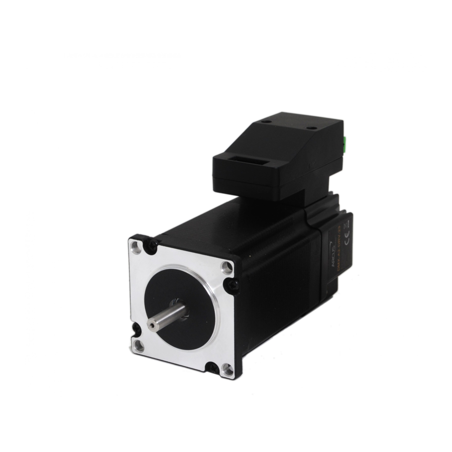
DMX-ETH is an integrated stepper controller + driver + motor motion product. Communication to the DMX-ETH can be established over Ethernet. It is also possible to download a stand-alone program to the device and have it run independent of a host. -
Page 8: Model Numbers
2 – Double 3 – Triple Motor Frame Size 17 – NEMA 17 Motor 23 – NEMA 23 Motor Contacting Support For technical support contact: support@arcus-technology.com. Or, contact your local distributor for technical support. DMX ETH Manual page 8 rev 1.16... -
Page 9: Electrical And Thermal Specifications
2. Electrical and Thermal Specifications Power Requirement Regulated Voltage: +12 to +48 VDC Current (Max): 3 A (peak) Temperature Ratings † -20°C to +80°C Operating Temperature: Storage Temperature: -55°C to +150°C † Based on component ratings Digital Inputs † Opto-isolated NPN inputs Type: +12 to +24 VDC Opto-isolator supply:... -
Page 10: Dimensions
3. Dimensions †All dimensions in inches Controller Figure 3.0 NEMA 17 Figure 3.1 DMX ETH Manual page 10 rev 1.16... - Page 11 NEMA 23 Figure 3.2 Model L (inches) DMX-ETH-17-2 1.58 DMX-ETH-17-3 1.59 DMX-ETH-23-2 DMX-ETH-23-3 Table 3.0 DMX ETH Manual page 11 rev 1.16...
-
Page 12: Motor Specifications
4. Motor Specifications Electrical Specifications NEMA Stack Current / Holding Resistance/ Inductance/ Inertia Size Size Phase † Torque Phase Phase Double 1.7A 0.44 N-m 3.0 mH 0.28 oz-in Triple 2.0A 0.59 N-m 2.7 mH 0.37 oz-in Double 2.8A 0.95 N-m 2.5 mH 1.64 oz-in Triple... -
Page 13: Torque Curve - Nema 23
Figure 4.1 Torque Curve – NEMA 23 Figure 4.2 DMX ETH Manual page 13 rev 1.16... - Page 14 Figure 4.3 DMX ETH Manual page 14 rev 1.16...
-
Page 15: Connections
5. Connections Figure 5.0 4-Pin Connector (5.08mm) Pin # In/Out Name Description Ground Power Input +12 to +48VDC Table 5.0 Mating Connector Description: 2 pin 0.2” (5.08mm) connector Mating Connector Manufacturer: On-Shore Mating Connector Manufacturer Part: †EDZ950/2 † Other 5.08mm compatible connectors can be used. Figure 5.1 14-Pin Connector (2mm) Pin #... - Page 16 LATCH Latch input HOME Home input -LIM Minus limit input +LIM Plus limit input Digital Input 1 Digital Input 2 Digital Output 1 Digital Output 2 Not Connected Not Connected Not Connected Not Connected Table 5.1 Mating Connector Description: 14 pin 2mm dual row connector Mating Connector Manufacturer: HIROSE Mating Connector Housing Part Number:...
-
Page 17: Dmx-Eth Interface Circuit
DMX-ETH Interface Circuit Figure 5.2 DMX ETH Manual page 17 rev 1.16... -
Page 18: Digital Outputs
Digital Outputs Figure 5.3 shows an example wiring to the digital output. Figure 5.3 WARNING: The maximum source current for digital outputs is 90 mA. Take caution to select the appropriate pull-down resistance to limit the source current below this level. Digital Inputs Figure 5.4 shows the detailed schematic of the opto-isolated inputs. -
Page 19: Getting Started
6. Getting Started Typical Setup Point-to-point Figure 6.0 Network-based Figure 6.1 DMX ETH Manual page 19 rev 1.16... -
Page 20: Windows Gui
Windows GUI DMX-ETH comes with a Windows GUI program to test, program, compile, download, and debug the controller. Startup the DMX-ETH GUI program and you will see following screen. Figure 6.2 A. Device IP of the DMX-ETH. The device IP can be changed. -
Page 21: Main Control Screen
Main Control Screen Figure 6.3 DMX ETH Manual page 21 rev 1.16... -
Page 22: Status
A. Status Figure 6.4 1. Pulse Counter – displays the current pulse position counter. When StepNLoop is enabled, this displays the Target position. 2. Encoder Counter – displays the current encoder position counter. 3. Delta Counter – valid only for StepNLoop. Displays the difference between the target position and the actual position. -
Page 23: Control
7. Move Mode – displays current move mode • ABS: all the move commands by X[pos] command will be absolute moves • INC: all the move commands by X[pos] command will be increment moves. 8. S-curve Status – Displays whether the moves are in trapezoidal or S-curve acceleration. -
Page 24: On-The-Fly Speed Change
• Accel: acceleration value in milliseconds • Decel: deceleration value in milliseconds 2. Enable Driver Power – use this button to enable and disable the power to the micro-step driver. 3. Select Acceleration Mode – use these buttons to select trapezoidal or S-curve acceleration mode. -
Page 25: Dio Status
2. Set SSPDM – Set the SSPDM parameter. Note that if an on-the-fly speed change operation is to be used, this parameter must be set before the controller starts motion. 3. Desired Speed – Once the “Set Speed” button is clicked, the speed will change on-the-fly to the desired speed. -
Page 26: Standalone Program File Management
Figure 6.8 Terminal dialog box allows manual testing of the commands from a terminal screen as shown in Figure 6.8. F. Standalone Program File Management Figure 6.9 1. Open – Open standalone program 2. Save – Save standalone program 3. New – Clear the standalone program editor DMX ETH Manual page 26 rev 1.16... -
Page 27: Variable Status
G. Variable Status Figure 6.10 View the status of variables 1-100. Note that this window is read-only. 1. Command line – To write to variable, use V[1-100] = [value] syntax. DMX ETH Manual page 27 rev 1.16... -
Page 28: Setup
H. Setup Figure 6.11 1. Polarity Setup – the following polarity parameters can be configured • Dir: direction of the motion (clockwise or counter-clockwise) • Home: home input polarity • Limit: limit input polarity • Latch: latch input polarity • Z-Index: Encoder Z index channel polarity •... -
Page 29: Product Information
• High: jump to line 0 • Enable: enable output polarity 2. Driver Setting – The following driver settings can be configured: • Micro-step: 2 to 500 micro-steps • Run Current: 100mA to 3Amp • Idle Current: 100mA to 3Amp •... -
Page 30: Standalone Processing
J. Program Control Figure 6.13 1. Program Status – program status shows here. Following are possible program status: Idle, Running, Errored and Paused. 2. Index – program that is downloaded is in the form of low-level code. Each line of the low level code has a line number which shows here. 3. -
Page 31: Standalone Program Editor
L. Standalone Program Editor Figure 6.15 1. Write the standalone program in the Program Editor 2. Use this button to remove the current standalone program Use this button to open a larger and easier to manage program editor. M. About Figure 6.16 Click this button to display the GUI version as well as the firmware version of the controller/driver. -
Page 32: Motion Control Overview
7. Motion Control Overview Important Note: All the commands described in this section are interactive commands and are not analogous to stand-alone commands. Refer to the “Standalone Language Specification” section for details regarding stand-alone commands. Motion Profile By default, a trapezoidal velocity profile is used. See Figure 7.0. Figure 7.0 High speed and low speed are in pps (pulses/second). -
Page 33: On-The-Fly Speed Change
For non on-the-fly speed change moves, set SSPDM=0. Digital Inputs/Outputs DMX-ETH comes with 2 digital inputs and 2 digital outputs. Inputs Read digital input status using the DI command. Digital input values can also be referenced one bit at a time by the DI[1-2] commands. -
Page 34: Motor Power
SUB31 is called will be line 0. Otherwise, it will be the line that caused the error. Positional Moves DMX-ETH can operate in either incremental or absolute move modes. Use X command to make moves. Use INC and ABS commands change the move mode. Use MM command to read the current move mode. -
Page 35: Jogging
Homing Home search sequence involves moving the motor towards the home or limit switches and then stopping when the relevant input is detected. The DMX-ETH has 5 different homing routines: Home Input Only (High speed only) Use the H+/H- command. -
Page 36: Home Input And Z-Index
Home Input and Z-index Use the ZH+/ZH- command. Figure 7.3 shows the homing routine. Figure 7.3 A. Issuing the command starts the motor from low speed and accelerates to high speed. B. As soon as the home input is triggered, the motor decelerates to low speed C. -
Page 37: Limit Only
E. The motor is now past the home input by the amount defined by the home correction amount (HCA). The motor now moves back towards the home switch at low speed. F. The home input is triggered again, the position counter is reset to zero and the motor stops immediately Limit Only Use the L+/L- command. -
Page 38: Motor Position
Motor Position Motor position can be set and read by using the PX command. Encoder position can be set and read by using the EX command. Motor Status Motor status can be read anytime by reading the response to the MST command. The following is the bit representation of motor status: Description Motor running at constant speed... -
Page 39: Latch Input
Latch Input The DMX-ETH module provides a high speed position latch input. This input performs high speed position capture of both pulse and encoder positions but does not reset the pulse or encoder position counters. Note: When StepNLoop mode is enabled, the position value should be ignored. - Page 40 is performed. Units are in encoder counts. Maximum error between target and actual position that is not considered a serious error. If the error exceeds Error Range this value, the motor will stop immediately and go into an error state. Maximum number of correction tries that the Correction Attempt controller will attempt before stopping and going into...
-
Page 41: Ip Address
Once SNL is enabled, the speed is in encoder speed. For example HSPD=1000 when SNL is enabled means that the target high speed is 1000 encoder counts per second. IP Address Set the IP address of the DMX-ETH module using the IP command. See default IP/socket settings below: 192.168.1.250... -
Page 42: Micro-Step Driver Configuration
Figure 7.7 Changing the IP Address: DMX-ETH provides the user with the ability to set the device IP of the module. To write the values to the device’s flash memory, use the STORE command. After a complete power cycle, the new IP will be written to memory. Note that before a power cycle is completed, the settings will not take effect. -
Page 43: Over Temperature Alarm
While reading or writing to the micro-step driver, StepNLoop control mode must be disabled. These control modes may interfere with the driver configuration. Over Temperature Alarm The integrated driver included with DMX-ETH is DMX-A2-DRV. This product is also available as a standard driver + motor-only product. See website for details. Warning: Do not dissemble top controller from the DMX-A2-DRV. -
Page 44: Standalone Programming
;* Wait for the move to complete V1=100 Multi-Threading: The DMX-ETH supports the simultaneous execution of two standalone programs. Program 0 is controlled via the SR0 command and program 1 is controlled via the SR1 command. For examples of multi-threading, please refer to the Example Stand- alone Programs section. -
Page 45: Communication Time-Out Feature (Watchdog)
2-pin connector. Hard Reset detection: After initial boot up, the DMX-ETH will begin to look for a hard reset input sequence. If the first input pattern is not detected within 5 seconds, boot-up will skip to “Connection detection”. -
Page 46: Hard Reset (Flash Memory)
Hard Reset (Flash Memory) DMX-ETH comes with the ability to reset all the flash parameters to factory default settings. This is especially useful if the user has forgotten the device IP. Hard reset is done by triggering the +LIM/-LIM/HOME/DI1/DI2 digital inputs in a particular sequence on boot up (See Boot-up Sequence section). -
Page 47: Storing To Flash
(i.e. it is not necessary to wait the full 10 sec to trigger the next step). If the DMX-ETH successfully triggers steps 1-7 in sequence, the flash is reset to factory default. At the end of the flash reset operation, the motor will stay enabled. -
Page 48: Ethernet Communication Protocol
8. Ethernet Communication Protocol DMX-ETH uses 10Mbps Ethernet ASCII communication over TCP/IP. Communication between the PC/PLC and DMX-ETH is done using standard socket programming. Socket Settings Port: 5001 ASCII Protocol Sending Command ASCII command string in the format of [ASCII Command][NUL] [NUL] character has ASCII code 0. -
Page 49: Ascii Language Specification
Refer to the “Standalone Language Specification” section for details regarding stand-alone commands. DMX-ETH language is case sensitive. All command should be in capital letters. Invalid command is returned “?”. Always check for proper reply when command is sent. - Page 50 DRVRC=[Value] Set driver run current setting. Value is only written to the driver after using the “RW” command. EDEC Get unique deceleration enable 0 or 1 EDEC=[Value] Set unique deceleration enable Returns driver power enable. 1 – Motor power enabled 0 –...
- Page 51 [2-7] – Driver write failure Read driver parameters Get return zero enable. Used during homing 0 or 1 RZ=[0 or 1] Set return zero enable. Used during homing Write driver parameters SASTAT[0,1] Get standalone program status 0 – Stopped 1 – Running 2 –...
-
Page 52: Error Codes
Homes the motor in negative direction using the home switch and then Z index encoder channel. Table 9.0 Error Codes If an ASCII command cannot be processed by the DMX-ETH, the controller will reply with an error code. See below for possible error responses: Error Code Description... -
Page 53: Standalone Language Specification
10. Standalone Language Specification Description: Comment notation. In programming, comment must be in its own line. Syntax: ; [Comment Text] Examples: ; ***This is a comment JOGX+ ;***Jogs axis to positive direction DELAY=1000 ;***Wait 1 second ABORT ;***Stop immediately all axes including X axis ABORTX Description: Motion: Immediately stop motion without deceleration. -
Page 54: Dec
Examples: JOGX+ ;***Jogs axis to positive direction DELAY=10000 ;***Wait 10 second ABORTX ;***Stop axis Description: Read: Gets the digital input value. DMX-ETH has 2 digital inputs. Syntax: Read: [variable] = DI Conditional: IF DI=[variable] ENDIF IF DI=[value] ENDIF Examples: IF DI=0 DO=1 ;***If all digital inputs are triggered, set DO=1... - Page 55 DI[1-2] Description: Read: Gets the digital input value. DMX-ETH has 2 digital inputs. Syntax: Read: [variable] = DI[1-2] Conditional: IF DI[1-2]=[variable] ENDIF IF DI[1-2]=[0 or 1] ENDIF Examples: IF DI1=0 DO=1 ;***If digital input 1 is triggered, set DO=1 ENDIF...
-
Page 56: Drvic
DRVIC Description: Write: Sets the driver idle current parameter Syntax: Write: DRVIC=[value] Examples: WHILE 1=1 IF DI1 = 0 ;***If DI1 is triggered, execute SL=0 ;***Disable StepNLoop DRVMS=100 ;***Micro-step set to 100 DRVIT=1 :***Idle-time set to 1 cent-sec DRVIC=100 ;***Idle-current set to 100 mA DRVRC=1000 ;***Run-current set to 1000 mA ;***Write driver parameters... -
Page 57: Eclearx
ECLEARX Description: Write: Clears motor error status. Also clears a StepNLoop error. Syntax: Write: ECLEARX Examples: ECLEARX ;***Clears motor error ECLEARSX Description: Write: Clears StepNLoop error status. ECLEAR also clears a StepNLoop error Syntax: Write: ECLEARSX Examples: ECLEARSX ;***Clears StepNLoop error ELSE Description: Perform ELSE condition check as a part of IF statement... -
Page 58: End
> Greater than < Less than >= Greater than or equal to <= Less than or equal to Not Equal to Examples: IF V1=1 X1000 WAITX ELSEIF V1=2 X2000 WAITX ELSEIF V1=3 X3000 WAITX ELSE WAITX ENDIF Description: Indicate end of program. Program status changes to idle when END is reached. -
Page 59: Endsub
ENDSUB Description: Indicates end of subroutine When ENDSUB is reached, the program returns to the previously called subroutine. Note: Sub 31 is reserved for error handling. Syntax: ENDSUB Examples: GOSUB 1 SUB 1 WAITX X1000 WAITX ENDSUB ENDWHILE Description: Indicate end of WHILE loop Syntax: ENDWHILE Examples:... -
Page 60: Gosub
Description: Read: Gets the current encoder position Write: Sets the current encoder position Syntax: Read: [variable] = E[axis] Write: EX = [0 or 1] EX = [variable] Conditional: IF EX=[variable] ENDIF IF EX=[value] ENDIF Examples: EX=0 ;***Sets the current encoder position to 0 GOSUB Description: Perform go to subroutine operation. -
Page 61: Homex[+ Or -]
HOMEX[+ or -] Description: Command: Perform homing using current high speed, low speed, and acceleration. Syntax: HOMEX[+ or -] Examples: HOMEX+ ;***Homes axis in positive direction HSPD Description: Read: Gets high speed. Value is in pulses/second Write: Sets high speed. Value is in pulses/second. Syntax: Read: [variable] = HSPD Write: HSPD = [value]... -
Page 62: Inc
Description: Command: Changes all move commands to incremental mode. Syntax: Examples: ;***Change to incremental mode PX=0 ;***Change position to 0 X1000 ;***Move axis to position 1000 (0+1000) WAITX X2000 ;***Move axis to position 3000 (1000+2000) WAITX JOGX[+ or -] Description: Command: Perform jogging using current high speed, low speed, and acceleration. -
Page 63: Ltx
Examples: LSPD=1000 ;***Sets the start low speed to 1,000 pulses/sec V1=500 ;***Sets the variable 1 to 500 LSPD=V1 ;***Sets the start low speed to variable 1 value of 500 Description: Write: Set latch enable Range is [0,1] Syntax: Write: LTX=[0,1] LTX=[variable] Examples: LTX=1... -
Page 64: Mstx
MSTX Description: Read: Get motor status Syntax: Read: [variable]=MSTX Conditional: IF MSTX=[variable] ENDIF IF MSTX=[value] ENDIF Examples: IF MSTX=0 DO=3 ELSE DO=0 ENDIF Description: Indicates the start of a program When END is reached, the program is concluded Syntax: PRG [program number] Examples: PRG 0 ;***Program 0... -
Page 65: Rwstat
Examples: JOGX+ ;***Jogs axis to positive direction DELAY=1000 ;***Wait 1 second ABORTX ;***Stop without deceleration V1=PS ;***Sets variable 1 to pulse speed Description: Read: Gets the current pulse position Write: Sets the current pulse position Syntax: Read: Variable = PX Write: PX = [value] PX = [variable] Conditional: IF PX=[variable]... -
Page 66: Scvx
SCVX Description: Write: Set s-curve enable. Range is from 0 or 1 Syntax: Write: SCVX=[0 or 1] SCVX=[variable] Note: If s-curve is enabled for an axis, on-the-fly speed feature can not be used for the corresponding axis. Examples: SCVX=1 ;***Sets axis to use s-curve acceleration: on-the-fly speed ;... -
Page 67: Sspdmx
Examples: SCVX=0 ;***Disable s-curve acceleration HSPD=1000 ;***X-axis high speed LSPD=100 ;***Set low speed ACC=100 ;***Set acceleration JOGX+ ;***Jogs to positive direction DELAY=1000 ;***Wait 1 second SSPDX=3000 ;***Change speed on-the-fly to 3000 PPS SSPDMX Description: Write: Set individual on-the-fly speed change mode Range is from 0 to 7 Syntax: Write: SSPDMX=[0-7]... -
Page 68: Sub
WAITX X1000 WAITX ENDSUB V[1-100] Description: Assign to variable. DMX-ETH has 100 variables [V1-V100] Syntax: V[Variable Number] = [Argument] V[Variable Number] = [Argument1][Operation][Argument2] Special case for BIT NOT: V[Variable Number] = ~[Argument] [Argument] can be any of the following: Numerical value... -
Page 69: Waitx
Examples: V1=12345 ;***Set Variable 1 to 123 V2=V1+1 ;***Set Variable 2 to V1 plus 1 V3=DI ;***Set Variable 3 to digital input value V4=DO ;***Sets Variable 4 to digital output value V5=~EO ;***Sets Variable 5 to bit NOT of enable output value WAITX Description: Command: Tell program to wait until move on the certain axis is finished before... -
Page 70: Zhomex[+ Or -]
Description: Command: Perform X axis move to target location With other Axis moves in the same line, linear interpolation move is done. Syntax: X[value] X[variable] Examples: ;***Absolute move mode X10000 ;***Move to position 10000 WAITX V10 = 1200 ;***Set variable 10 value to 1200 XV10 ;***Move axis to variable 10 value WAITX... -
Page 71: Example Standalone Programs
11. Example Standalone Programs Standalone Example Program 1 – Single Thread Task: Set the high speed and low speed and move the motor to 1000 and back to 0. HSPD=20000 ;* Set the high speed to 20000 pulses/sec LSPD=1000 ;* Set the low speed to 1000 pulses/sec ACC=300 ;* Set the acceleration to 300 msec EO=1... -
Page 72: Standalone Example Program 4 - Single Thread
Standalone Example Program 4 – Single Thread Task: Move the motor back and forth between position 1000 and 0 only if the digital input 1 is turned on. HSPD=20000 ;* Set the high speed to 20000 pulses/sec LSPD=1000 ;* Set the low speed to 1000 pulses/sec ACC=300 ;* Set the acceleration to 300 msec EO=1... -
Page 73: Standalone Example Program 6 - Single Thread
Standalone Example Program 6 – Single Thread Task: If digital input 1 is on, move to position 1000. If digital input 2 is on, move to position 2000. If digital input 3 is on, move to 3000. If digital input 5 is on, home the motor in negative direction. -
Page 74: Standalone Example Program 7 - Multi Thread
Standalone Example Program 7 – Multi Thread Task: Program 0 will continuously move the motor between positions 0 and 1000. Simultaneously, program 1 will control the status of program 0 using digital inputs. PRG 0 ;* Start of Program 0 HSPD=20000 ;* Set high speed to 20000pps LSPD=500... -
Page 75: Standalone Example Program 8 - Multi Thread
Standalone Example Program 8 – Multi Thread Task: Program 0 will continuously move the motor between positions 0 and 1000. Simultaneously, program 1 will monitor the communication time-out parameter and triggers digital output 1 if a time-out occurs. Program 1 will also stop all motion, disable program 0 and then re-enable it after a delay of 3 seconds when the error occurs. - Page 76 Appendix A: Speed Settings Speed Min. HSPD value Min. ACC Window LSPD Max ACC setting [ms] δ [PPS] † [ms] [SSPDM] value 1 - 16 K 16K - 30 K 30K - 80 K 80K - 160 K ((HSPD – LSPD) / δ) × 1000 160K - 300 K 300K - 800 K 18 K...
- Page 77 Acceleration/Deceleration Range – Positional Move When dealing with positional moves, the controller automatically calculates the appropriate acceleration and deceleration based on the following rules. Figure A.1 1) ACC vs. DEC 1: If the theoretical position where the controller begins deceleration is less than L/2, the acceleration value is used for both ramp up and ramp down.
- Page 78 Contact Information Arcus Technology, Inc. 3159 Independence Drive Livermore, CA 94551 925-373-8800 www.arcustechnology.com The information in this document is believed to be accurate at the time of publication but is subject to change without notice. DMX ETH Manual page 78...
Need help?
Do you have a question about the DMX-ETH and is the answer not in the manual?
Questions and answers