
Subscribe to Our Youtube Channel
Related Manuals for KREYER CHILLY MAX


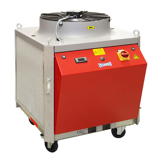
Summary of Contents for KREYER CHILLY MAX
- Page 1 I N S T R U C T I O N M A N U A L C H I L L Y M A X WTG – Wine Technology GmbH Moselstrasse 9 • D-54349 Trittenheim Tel: +49 (0) 65 07 - 938 180 Fax: +49 (0) 65 07 - 938 188 • kreyer@kreyer.com www.kreyer.com...
- Page 2 OPERATING INSTRUCTIONS SAFETY / PREVENTION OF ACCIDENTS TRANSPORT INSTALLATION AND INITIAL OPERATION CARE AND MAINTENANCE FAULT DIAGNOSIS IMPORTANT INFORMATION ON WATER QUALITY PLATE HEAT EXCHANGER (OPTION) WASTE DISPOSAL APPENDIX - TECHNICAL DATA - TEMPERATURE CONTROLLER - WIRING DIAGRAM These operating instructions have to be read carefully before putting the chiller into operation.
- Page 3 SAFETY / PREVENTION OF ACCIDENTS General information These operating instructions contain valuable information which has to be observed during initial start-up, operation and maintenance. Therefore these instructions are to be read by the installer and operating personnel in charge, before putting the chiller into operation. All general safety instructions mentioned in this chapter and special security instructions given in other sections of this manual have to be observed.
- Page 4 SAFETY / PREVENTION OF ACCIDENTS Non-permissible operating methods The operational safety of the delivered unit is guaranteed only if the unit is properly used as intended. Limits indicated in the technical data must not be exceed Health hazards with the refrigerant The refrigerant has only a very low acute health hazard.
- Page 5 TRANSPORT The chiller may only be transported in original packaging to the site of initial operation. In case of damage the manufacturer must be informed immediately. If the unit is moved to another location in a factory, all connections must be disconnected from the unit. Moving the unit to another location must be carried out without causing damages.
- Page 6 INSTALLATION AND INITIAL OPERATION Installation Prior to installation and commissioning of the chiller, please observe the following points strictly: The fresh air intake temperature may not exceed the max.ambient temperature (refer to name plate) Assure that the required quantity of air is available at air cooled chillers. Assure that the chiller hot air outlet does not warm up the environment or room excessivly.
- Page 7 INSTALLATION AND INITIAL OPERATION Options Option No 1: Hot air outlet to top The most frequent example. Air is taken in and evacuated in the same room. A large sized room is required. Hot air outlet: min. 3 m Fresh air intake: min.1 m Fresh air intake Note: The hot air outlet may not...
- Page 8 INSTALLATION AND INITIAL OPERATION Electrical connection The chiller is ready for connection and should only be connected to a three phase current network (mains voltage refer to technical data). The power supply has to be connected in a right handed rotatory fi eld. In order to confi rm the correct connection the direction of rotation of the fan motor must turn in the same direction as the arrow.
- Page 9 INSTALLATION AND INITIAL OPERATION Refi lling of the tank Automatic refi ll (Option) Tap/fresh water feed connected to water supply port guarantees constant level in the tank, so that eva- porator always remains submerged. Manual refi ll (Option) Filling of water manually through water inlet port or directly into tank. The waterlevel can be observed by the water sightglass which can be seen from the outside of the housing .
- Page 10 INSTALLATION AND INITIAL OPERATION Bleeding of the pump Remove bleeding screw P Reinstall bleeding screw and tighten as soon as medium exits from fi ller fi tting. CH pump CR pump Bleeding screw: P Drain screw Operating Instructions...
- Page 11 INSTALLATION AND INITIAL OPERATION Start–up of chiller Control switch »Standard«: After successful completion of all instructions given in this chapter, the refrigerating plant is switched on by means of the main switch or master switch (if installed). The OPERATION light will light up during normal operation.
- Page 12 CARE AND MAINTENANCE General In case of irregularities occurring during operation or extraordinary noise, the chiller has to be switched off by means of the control or main switch.(please contact the manufacturer) Fluid (water) Cleanliness of the water/fl uid should be tested daily. If required, the water/fl uid has to be drained and the evaporator, tank and pump has to be rinsed or cleaned.
- Page 13 CARE AND MAINTENANCE Refi lling of fl uid Automatic refi ll (option) Automatic water feed guarantees constant level in the tank, ensure that the evaporator always remains submerged. Float valve function has to be tested regularly. Manual refi ll (option) Ensure that the evaporator is always submerged.
- Page 14 FAULT DIAGNOSIS By means of the following instructions a quick failure analysis can be made. The user can repair some failures without any assistance. Please do not hesitate in phoning the manufacturers after sale service department if assistance is required. Corrective maintenance of the refrigeration cycle must be performed by competent refrigeration specialists only.
- Page 15 FAULT DIAGNOSIS (parts are identifi ed on the wiring diagram) Fault Possible cause Repairement Compressor clixon cuts out Compressor current too high Incorrect power supply L1, L2, L3 testing of ocurrent (ampere) Current and power supply OK: compressor or clixon defect Compressor defect Repairement only by refrigeration specialist...
- Page 16 FAULT DIAGNOSIS (parts are identifi ed on the wiring diagram) Fault Possible cause Repairement Overload tripped Resetting of overload Current of the specifi c Testing of current (ampere), part too high replace defect part Burnt or broken cable Repair broken cable Loose connection Tighten all contacts and terminals Insuffi...
- Page 17 FAULT DIAGNOSIS (parts are identifi ed on wiring diagram) Fault Possible cause Repairment Unit does not start No power supply Test power supply Broken main fuse Replace main fuse Transformer fuse broken Replace transformer fuse Temperature controller Replace temperature broken controller Fluid temperature Testing of correct...
- Page 18 IMPORTANT INFORMATION ON WATER QUALITY In order to achieve a correct and trouble-free operation on your water chiller it is necessary to examine the water quality and, when necessary, carry out water treatment. Corrosion, furring and biological problems can occur in the water system. The following information is important for the assessment of a half-open system: - water quality - all materials having contact with the cooling water...
- Page 19 IMPORTANT INFORMATION ON WATER QUALITY For assistance regarding watertreatment please contact: GERMANY Nalco Deutschland GmbH Ludwig-Landmann-Strasse 405 D-60486 Frankfurt am Main Phone: 069-793-40 Fax: 069-793-4295 FRANCE Nalco N°5 rue Rosa Bonheur F-59290 Wasquehal Phone: 03 20 11 70 00 Fax: 03 20 11 70 70 EUROPE Nalco European Operations...
- Page 20 PLATE HEAT EXCHANGER (OPTION) Cleaning of plate exchanger Soldered heat exchanger: For the removal of lime- and rust deposits, purifying agent SWEPcip AS, RS, CS or S (according to material) is suitable. Cleaning may be performed by means of SWEP cleaning device C.I.P 90 (circulation method) or a stationary pump.
- Page 21 FOR YOUR NOTICE Operating Instructions...
- Page 22 T E C H N I C A L D A T A S H E E T ======================================= Cooler Type: Chilly Max 90 --------------- 1. GENERAL DATA --------------- R410A Refrigerant gas: Specifications: --------------- Nominal ambient air: °C Coolant temperature: °C...
- Page 23 -------- 5. PUMP: -------- First PUMP: horizontal centrifugal pump Type: CH2-50 Number: Unit Total absorbed power: 0.80 Full load current: 1.25 Nominal flow rate: m³/h 1.50 Nominal pressure rate: 3.80 --------------- 6. LIQUID TANK: stainless steel --------------- Volume: 25.00 Outlet / inlet connections: Inch IG 3/4 ----------------------------...
- Page 24 Sensor PRG / MUTE Adjustment of the water LED direct reverse direct flow temperature mute LED reverse Sensor SEL Set value controlled Down Display Decimal point Description of the controller Display: During normal operation display indicates value measured by sensor. In case of alarm measured value and alarm code are indicated alternately.
- Page 25 Elektrodokumentation Electrical documentation Anschlußdaten Maschinentyp Chilly Max 90 Technical data Type Anschlußspannung 400 V +- 10 % Voltage Frequenz 50 Hz frequency Steuerspannung 1 24 V AC control voltage 1 Steuerspannung 2 control voltage 2 Anschlußleistung 7,1 KW Total absorb power Max.
- Page 26 0,71 kW 1,4 A 0,8KW 1,25A Kompressor Lüfter Pumpe Einspeisung compressor pump power supply Datum 16.12.2008 Zeichng. Hauptstromkreise E0007196 Bearb. Bruchhof Blatt Gepr. Wiebe Main circuit Chilly Max 90 Zust. Änderung Datum Name Ursp. Ers. f. Ers. d. Blatt Norm...
- Page 27 With removal of PE-connection you need an isolation control 3,0KW 4,4A Heizung Steuerspannung heater control voltage Datum 16.12.2008 Zeichng. Hauptstromkreise E0007196 Bearb. Bruchhof Blatt Gepr. Wiebe Main circuit Chilly Max 90 Zust. Änderung Datum Name Ursp. Ers. f. Ers. d. Blatt Norm...
- Page 28 15.0 OUT 1 OUT 2 Schwimmerschalter level switch I=Kühlen/cooling Kompressor Heizung compressor heater Datum 16.12.2008 Zeichng. Steuerstromkreise E0007196 Bearb. Bruchhof Blatt Gepr. Wiebe Control circuit Chilly Max 90 Zust. Änderung Datum Name Ursp. Ers. f. Ers. d. Blatt Norm...
- Page 29 Pumpe Kennbuchstabe : B pump rückfallverzögert mit Hilfsspannung Einstellung : 30m/50 % Datum 16.12.2008 Zeichng. Steuerstromkreise E0007196 Bearb. Bruchhof Blatt Gepr. Wiebe Control circuit Chilly Max 90 Zust. Änderung Datum Name Ursp. Ers. f. Ers. d. Blatt Norm...
- Page 30 T1/F1 Datum 16.12.2008 Zeichng. Schaltschrankaufbau E0007196 Bearb. Bruchhof Blatt Gepr. Wiebe Switch-box structure Chilly Max 90 Zust. Änderung Datum Name Ursp. Ers. f. Ers. d. Blatt Norm...
- Page 31 24 V AC SIEMENS 10481 contactor Steuerschalter 3SB32 02-2KA11 SIEMENS 12438 control switch Datum 16.12.2008 Zeichng. Stückliste E0007196 Bruchhof Bearb. Bill of Materials Blatt Gepr. Wiebe Chilly Max 90 Zust. Änderung Datum Name Ursp. Ers. f. Ers. d. Blatt Norm...
- Page 32 10395 auxiliary switch Hilfsschalter zu S1 3SB1400-OC , 1Ö SIEMENS 21955 auxiliary switch Datum 16.12.2008 Zeichng. Stückliste E0007196 Bruchhof Bearb. Bill of Materials Blatt Gepr. Wiebe Chilly Max 90 Zust. Änderung Datum Name Ursp. Ers. f. Ers. d. Blatt Norm...
- Page 36 OVERVIEW WTG – Wine Technology GmbH Moselstrasse 9 • D-54349 Trittenheim Tel: +49 (0) 65 07 - 938 180 Fax: +49 (0) 65 07 - 938 188 • kreyer@kreyer.com www.kreyer.com...
Need help?
Do you have a question about the CHILLY MAX and is the answer not in the manual?
Questions and answers