Table of Contents
Advertisement
Quick Links
Advertisement
Table of Contents
Troubleshooting

Related Manuals for Hardy Process Solutions HI 1756-FC

Summary of Contents for Hardy Process Solutions HI 1756-FC
- Page 1 HI 1756-FC Feeder Control Module User’s Guide Hardy Process Solutions Part Number: 0596-0318-01 Rev C Corporate Headquarters 10075 Mesa Rim Road San Diego, CA 92121-5201 Phone: 1-858-292-2710 Phone: 1-800- 821-5831 FAX: (858) 278-6700 Web-site: http://www.hardysolutions.com...
- Page 2 (Standard Hours 6:00 AM to 5:30 PM Pacific Standard Time) and weekends Option 4. Outside the U.S Hardy Process Solutions has built a network of support throughout the globe. For specific field service options available in your area please contact your local sales agent or our U.S.
-
Page 3: Table Of Contents
Power Check ..............................11 LEDS ................................. 11 Setting Up Communications ........................12 Linking the PLC with the HI 1756-FC Feeder Control Module ..............12 Configuration Output Table Overview ..................... 13 First Word - 0: Command Number ......................13 Command Return or Error Codes ......................15 ●... - Page 4 Second Word - 1: Format Word ........................ 15 Format Word Decimal Point Parameters ....................15 Third / Fifth Words - 2, 3, 4: Parameter Number and Value ..............16 Parameter 13-18 Refills ......................... 21 REC Parameters ............................23 Rate Calibration Parameters ........................24 Input Table ..............................
- Page 5 General Policies and Information ......................46 Warranty ..............................46 For Further Information Contact ....................... 47 INDEX ........................ 48 ● ● Contents ● ● ●...
-
Page 6: Chapter 1 Overview
The module supports both C2 electronic calibration and hard calibration (i.e., traditional calibration with weights). The HI 1756-FC is a loss-in-weight controller that measures the flow rate from a feeding device located on a process weighing scale. The user enters the flow parameters, and an HI 1756-FC algorithm automatically calculates and adjusts the tuning parameters needed to maintain the desired rate. -
Page 7: Typical Applications
C2® capabilities (e.g., the HI 1756-FC). Each Hardy Process Solutions C2-certified load sensor outputs digital information used for calculating the calibration. When the HI 1756- FC reads the signals from the load sensors, it calibrates the scale based on the load sensor’s output plus a user-supplied reference point value (from 0 to any known weight... - Page 8 to isolate the faulty component. Further, the DVM readings can be used to level a system and to make corner adjustments to platform scales. Accuracy is +/- 2% or better of full scale. NOTE If you do not have the HI 215IT or HI6010IT Junction Box connected to the module, the mV/V reading is the total for all load cells on the system.
-
Page 9: Chapter 2 Specifications
Chapter 2 Specifications ● ● ● ● ● Chapter 2 provides specifications for the HI 1756-FC feeder controller and other equipment that may come with the package. The specifications listed are designed to assist in the installation, operation and troubleshooting of the instrument. All service personnel should be familiar with this section before installing or repairing the instrument. -
Page 10: Power And Utility Requirements
C2® Maximum Cable Length 1000’ for C2, Non C2, or JB Card 250’ for IT Load Cell Excitation 5 VDC +/- 1.15 W maximum. Isolation from digital section 1000 VDC minimum C2 Calibration Output Isolation from digital section 1000 VDC minimum Number of Channels 1 Channel Update Rate... -
Page 11: Pending Approvals
Operating Temperature Range 0 to 60º C (32º F to 140º F) Temperature Coefficient Less than 0.005% of full scale per degree C for Cal-LO and Cal-HI reference points Storage Temperature Range -40 to 85º C (-40 to 185º F) Humidity Range 0-90% (non-condensing) Approvals... -
Page 12: Chapter 3 Installation
The Customer Support Department for parts or service. Step 4. Be sure to complete the warranty registration on the Hardy web site. Installing the HI 1756-FC Allen-Bradley ControlLogix Processor or Remote Rack WARNING Electrostatic discharge may damage semiconductor components in the module. -
Page 13: Removing The Module From The Chassis
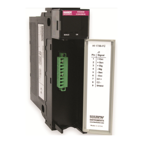
I/O male connector into the I/O connector at the front of the module. HI 1756-FC with door open Note When the door is open, the button you see on the top right has no function. Check to be sure that the connector is completely... -
Page 14: Load Cell Wiring Diagrams
HI 1756 Remote Terminal Assembly (HI 1756-XX-RT) The Remote Terminal Assembly (RTA) provides connection points between the cable assembly from the HI 1756-FC module and the individual wires from the junction box(es) or load sensor(s). The RTA comes with a standard 35 mm Din Rail Mounting and requires at least a 5”... -
Page 15: Hardy Hi 215It Junction Box
Jumpers RTA with jumpers for load cells without sense lines RTA Cable Assembly and Jumpers A six-foot cable connects to the HI 1756-FC module. RTA cable assembly - HI 1756WS RTA cable schematic Hardy HI 215IT Junction Box 1756 FC... -
Page 16: Chapter 4 Configuration
Chapter 4 Configuration ● ● ● ● ● Chapter 4 covers the settings used to prepare the controller for calibration and operation. The Setup procedures require Allen-Bradley’s RS Logix 5000, Allen-Bradley RSLinx™ or RSLinx™ Lite. Power Check To make or change settings, there must be power to both the PLC and the module. -
Page 17: Setting Up Communications
Setting Up Communications Linking the PLC with the HI 1756-FC Feeder Control Module To set parameters for the weigh scale module, you must establish communications with a ControlLogix PLC. Follow the steps below to set up the communication link. You will need a new or open RS Logix®... -
Page 18: Configuration Output Table Overview
Configuration Output Table Overview To configure the module, you send commands via the PLC output table. The 1756 module uses 32 16-bit INT words in and out. Only 5 words of the output table are normally used. (Command 0X5E uses ten and 0X5F uses seven) Word Command structure write Command number... - Page 19 them. This calibration operates at points 2 and 4 of a 5-point rate calibration. The other points are filled with data based on these 2 points. Runs the 5-point rate calibration at whatever points RATE_CAL_5POINT_CMD 0x60 have previously been defined. Runs the 2-point rate calibration at whatever points RATE_CAL_2POINT_CMD 0x61...
-
Page 20: Command Return Or Error Codes
Command Return or Error Codes Commands always return the command word and command status. The command status word may include the following codes: Return Codes # Hex Description SUCCESS Pass OUTOFTOLERANCE Out of tolerance INDEXOUTOFRANGE Out of range NOSUCHCMD Command bad C2FAILNODEVS No C2 devices C2FAILCAPEQ... -
Page 21: Third / Fifth Words - 2, 3, 4: Parameter Number And Value
Third / Fifth Words - 2, 3, 4: Parameter Number and Value The third and fourth words in the output table, Parameter Value, are used by the WRITEPARAM command. The fifth word is the parameter ID, used by the WRITEPARAM and READPARAM commands. Parameter values are written with the least significant word first and one 32-bit integer per parameter. - Page 22 REC Level 1 decimal place. Must be > or = 0. REC Time Seconds, 0 decimal places. Must be > or = 0 REC Shutdown 0=no, 1=yes Shutoff Percent 0 decimal places. 0-100 Total Total DP Batch Total Total DP. Must be > or = 0 Low Alarm Shut Down Rate Rate DP.
- Page 23 Bit 12 Initial Refill Mode Two decimal places. This it the output percent when in MANUALOP MANUAL mode. Lightly averaged rate of change, read only, RATE decimal FAST_ROC places. zerocount 0x0A00 AD counts at zero weight calLowCount 0x0A01 Numbers or letters in the titles below correspond to the values in Column 2, Hex#, above Parameter 2 Metric (Unit of Measure) The Unit parameter sets the scale and related displays to one of the following options:...
- Page 24 Chapter One provides a detailed description of WAVERSAVER’s function and purpose. In short, WAVERSAVER helps to mitigate the effects of vibratory forces, allowing the HI 1756-FC to distinguish between actual weight data and mechanical noise in the signals the load cell sends. WAVERSAVER can be configured to ignore noise with frequencies as low as 0.25 Hz.
- Page 25 NOTE You must calibrate the scale prior to rate calibration. The PI controller calculates an output percentage based on the parameters P (proportional) and I (integral). The rate calibration process can set the values for P and I automatically. The output percent is determined by the formula: P*((Setpoint - ActualRate)/MaxRate + I * (integral of the proportional term)).
-
Page 26: Parameter 13-18 Refills
There are thee options: OFF: (default) Turns off the function. ON-LEARN: (works only with Auto Refill) The HI 1756-FC saves the % output and change in weight values from previous refills and continuously calculates the optimal Output % based on these values. This allows the instrument to adjust as conditions and the material or refill characteristics change over time. - Page 27 ON-FIXED: With Auto Refill, you can use ON-FIXED to either lock in an effective learned value or enter a noted value that has worked well on previous applications. Range: 0, 1 or 2 Parameter 18 OP Adjust %/wgt during refill Refill OP Adjust %/wgt This is the OP (Output Percentage) Adjust % per unit of wgt.
-
Page 28: Rec Parameters
REC mode beyond the time limit set in REC Time. If you select YES for REC Shutdown and the RE error goes beyond the REC Time, the HI 1756-FC goes to shutoff mode. If you select NO, once the deviation goes beyond the REC Time, the system only sends an alarm bit. -
Page 29: Rate Calibration Parameters
Rate Calibration Parameters Three types of calibrations determine the flow rate per output percentage: 1. Two-point rate calibration: Used for Auto RateCal. If a two-point Auto Rate Calibration is selected, two flow rate points (points two and four) are used for calculating other rate point values. -
Page 30: Input Table
1. For the 2 pt Cal Type (Pt2 and Pt4), the two flow rates for the percentages you selected are the actual flow rates. The instrument calculates the remaining three flow rates. 2. For the 5 pt Cal Type, you provide the five RateCal percents between the Low and High output percentages. -
Page 31: States (Word 12 Of Input Table)
VERSION Firmware version STATUS Statusword (See Statusword below) COUNTER Statusword At word 14, the module returns a binary statusword where each bit indicates a state or condition within the module. To interpret these states, note which bits are ON and use the chart below to match each bit location to the state it represents. -
Page 32: Cip Messages
JBOX, the instrument can also read the weights and voltages of the individual sensors attached to the IT JBOX. To initiate an IT test, do a WRITEPARAM command, with parameter number 0x0036, and a parameter value equal to the number of sensors, which should be 1-4 if you have an IT JBOX. - Page 33 1. Command 1: Read calibration values. Use this command to read the rate and weight calibration values. 2. Command 0x81: Write rate calibration values. Use this command to set the 7 rate calibration pairs. 3. Command 0x82: Write weight calibration. Use this command to set the 3 weight calibration values: zero counts, low counts, and CalibK (weight per A/D count).
-
Page 34: Chapter 5 Calibration
Chapter 5 Calibration ● ● ● ● ● The Feeder Controller Module should be calibrated before use. We also recommend that you verify the calibration periodically or when not in use for extended periods of time. Users and service personnel should be familiar with the procedures in this chapter before installing or operating the Feeder Controller Module. -
Page 35: Load Check
capacity is rated at 1000 pounds, the load cell/point will be 10 mVDC at 1000 pounds, 7.5 mVDC at 750 pounds, 5 mVDC at 500 pounds and so on. A zero reference point will vary from system to system depending on the “Dead Load” of the vessel. -
Page 36: Hard Calibration
The Hard Calibration Ladder Logic Example is located at the Hardy Process Solutions Inc. Web Site. See http://www.hardysolutions.com. Click products > PLC Weighing Modules > HI 1756-FC. Click on the Docs & Programs tab and scroll down to Programs and Firmware. Select HI 1756-FC Sample Programs for the Ladder Logic example. -
Page 37: Chapter 6 Troubleshooting
● ● ● ● ● Chapter 6 provides procedures for troubleshooting the electrical, mechanical and firmware elements of the HI 1756-FC and for using Hardy’s Integrated Technician (IT®) software utility to isolate problems. Flow charts provide troubleshooting s for the rate controller, load cells, and cabling. -
Page 38: It Test
Millivolt/volt equals the output from a load cell per each volt of excitation. The HI 1756-FC reads the load cell output in mV/V, which provides higher resolution (4 decimal places) than an mV reading. This provides more sensitivity to help you troubleshoot the condition of the load cell under certain conditions. -
Page 39: A1 - Guidelines For Instabilities On Formerly Operating System
A1 - Guidelines for Instabilities on Formerly Operating System UNSTABLE RATE CONTROLLER Disconnect external signal cables and shields, except AC Power Monitor the reading for stability STABLE? Reconnect signal Problem could be in cables one at a the instrument. Contact time Hardy Customer Support PH: 800-821-5831... -
Page 40: B - Guidelines For Instabilities On Formerly Operating Systems (Cont'd)
B - Guidelines for Instabilities on Formerly Operating Systems (Cont’d) Check for Electrical Stability Check for Mechanical Stability Check Configuration settings for stability Go To Stability ● ● Chapter 6 ● ● ●... -
Page 41: B1 - Guidelines For Instabilities On Formerly Operating Systems (Cont'd)
B1 - Guidelines for Instabilities on Formerly Operating Systems (Cont’d) Electrical Physical Grounding - All common equipment share a common ground point. B1.1 Keep the ground cable length to earth ground as short as possible. Install a new ground rod if the cable length is excessive. Cable - Cuts or breaks in the load cell insulation allow moisture to wick into the B1.2... -
Page 42: B1 - Guidelines For Instabilities On Formerly Operating Systems (Cont'd)
B1 - Guidelines for Instabilities on Formerly Operating Systems (Cont’d) Vessel - When inspecting a vessel, the Center of Gravity (COG) should be low and centered equally over all the load cells. Insure the load is directly over or under the load point to avoid side-loading and that there isn’t any side loading from piping or external forces. -
Page 43: F - Verify Individual Load Cell Millivolt Readings
F - Verify Individual Load Cell Millivolt Readings Testing an individual load cell signal output requires an IT Summing Junction box or millivolt meter. Use the load cell certificate to verify the millivolt per volt (mV/V) rating: Example: 3mV/V load cells produce approximately 15mV at full load. That is 5 volts excitation x 3 mV/V. -
Page 44: G - Calibration Failed
G - Calibration Failed: Not Enough Counts Between ZERO and SPAN This error only occurs at the SPAN parameter. You may ZERO out chains and temporary calibration equipment to hold or hoist test weights. Zeroing the temporary weight does not effect the calibration. The difference between zero and span is less than 1000 counts Using a millivolt meter, verify that:... -
Page 45: H - Mechanical Inspection
H - Mechanical Inspection 1) Keep flexures on the horizontal 2) Vertical flexures should be avoided 3) Do not use flexures to correct for misaligned piping 4) Do not use hose flexures to make right angle bends 5) Non-flexed piping should have an unsupported horizontal run using a ratio of 36 times it’s diameter 6) Pipe flexure lengths should be a ratio of 6 times it’s diameter 7) Feed and discharge piping flexed... -
Page 46: J - Electrical Inspection
J - Electrical Inspection DO NOT POWER UP THE CONTROLLER UNTIL INPUT VOLTAGES CAN BE VERIFIED 1) Verify the proper input power, AC or DC, is properly installed 2) Use a meter to verify neutral, ground and hot are correct Isolated from SCR and motor control circuits Use a Common earth ground. -
Page 47: K - Load Sharing And Load Sensor Checkout
K - Load Sharing and Load Sensor Checkout ● ● Chapter 6 ● ● ●... -
Page 48: Erratic Weight Or Rate Control
Erratic Weight or Rate Control This section explains how to resolve problems relating to rate and Rate of Change (ROC) calculation, Rate Exception Control (REC), motor speed control, and weight calibration. Rate calculations 1. Rate calculations are no better than the scale’s calibration accuracy. Verify the scale calibration using test weights. -
Page 49: System And Load Cell Tests
System and Load Cell Tests Overview of Typical Load Cell System The typical load cell system consists of one or more load cells/points and an HI 1756-FC Rate Controller. If you have more than one load point, an optional summing junction box can read data for individual load cells. -
Page 50: Integrated Technician (It®)
The load cell/point takes as an input the 5 volts DC excitation voltage generated by the HI 1756-FC. It generates a millivolt output proportional to the weight on the scale (0- 10mV DC for 2mV/V load cells/points or 0-15mV DC for 3mV/V load cells/points). -
Page 51: Weight And Voltage Test
When you check the results, if all the load sensors read 0.00, something is probably wrong between the HI 1756-FC and the HI 215IT junction box, e.g., the cable may be disconnected. Something could also be causing the box to not transmit the readings to the HI 1756-FC. -
Page 52: For Further Information Contact
For Further Information Contact Hardy Technical Services Hardy Process Solutions, 10075 Mesa Rim Road, San Diego, CA 92121 Telephone: +1 (858) 292-2710 Option 4 FAX: +1 (858) 278-6700 Web Site: http://www.hardysolutions.com... -
Page 53: Index
Index A D ABORTCMD, 13 Deinstalling the Module, 8 Alarm Delay, 22 Digital Volt Meter, 2 Alarm LEDs, 11 Din Rail Mounting, 9 alarms, 2 DVM - Digital Volt Meter, 2 Applications, 2 Approvals, 6 E Automatic mode, 3 Automatic refill, 3 End Weight, 21 Automatic Refill, 21 Error Codes, 15... - Page 54 L R LEDs, 11 Rate Calibration, 24 Linking PLC to the HI 1756 FC, 12 Rate Calibration Parameters, 24 Load Cell, 29 Rate Calibration PID P, 19 Load Cell Excitation, 5 Rate Decimal Point, 15 Load Cell Tests, 44 Rate Exception Control (REC), 43 Load Cell Wiring, 9 Rate of Change (ROC) calculation, 43 Loss of weight, 1...
- Page 55 U W UL, 6 Wait Time, 22 Update Rate, 5 WAVERSAVER, 2, 5, 19 Weighing System Tests, 3 Weight and Voltage Testing, 32 V Weight and Voltage tests, 46 weight calibration, 43 VERSION, 26 Weight Decimal Point, 15 Voltage, 5 Wiring Diagrams, 9 Voltage Testing, 32 WRITENONVOLATILE, 13, 16...
- Page 56 All information within is subject to change without notice. Visit our website for latest specifications. WAVERSAVER, C2, IT, ADVANTAGE and ANY-WEIGH are registered trademarks of Hardy Process Solutions, Inc.. Allen-Bradley, CompactLogix, MicroLogix and Encompass are trademarks of Rockwell Automation, Inc. All other trademarks or...
Need help?
Do you have a question about the HI 1756-FC and is the answer not in the manual?
Questions and answers