
Related Manuals for Crestron Electronics DM NVX Series


Summary of Contents for Crestron Electronics DM NVX Series
- Page 1 DM NVX® Network AV Encoders/Decoders DM-NVX-350 DM-NVX-351 DM-NVX-352 DM-NVX-350C DM-NVX-351C DM-NVX-352C Product Manual Crestron Electronics, Inc.
- Page 2 Crestron, the Crestron logo, 3-Series, Crestron Toolbox, DigitalMedia, DM NAX, DM NVX, DM NVX Director, and XiO Cloud are either trademarks or registered trademarks of Crestron Electronics, Inc. in the United States and/or other countries. Audinate and Dante are either trademarks or registered trademarks of Audinate Pty Ltd. in the United States and/or other countries.
-
Page 3: Table Of Contents
Contents Introduction ............................ 1 Physical Description ........................2 DM-NVX-350, DM-NVX-351, and DM-NVX-352 .................. 2 Front Panel, DM-NVX-350 and DM-NVX-351 ................2 Front Panel, DM-NVX-352 ......................... 4 Rear Panel ............................. 5 DM-NVX-350C and DM-NVX-351C ......................7 DM-NVX-352C ............................8 Configuration and Status ......................10 DMF-CI-8 Chassis Details ........................ - Page 4 Adaptive Bit Rate ............................. 36 Using the Web Interface ........................36 Using SIMPL Windows ........................37 Subscriptions ............................37 Using the Web Interface ........................38 Using SIMPL Windows ........................39 Daisy Chain .............................. 40 Switching Subscribed Transmitters ..................... 40 Switching Nonsubscribed Transmitters ..................41 7.1 Surround Sound Audio ........................
-
Page 5: Introduction
Introduction Crestron® DM NVX® network AV encoders/decoders transport ultra high-definition 4K video with 60 Hz frame rates and 4:4:4 color sampling over standard Gigabit Ethernet. Support for High Dynamic Range (HDR) video and HDCP 2.2 ensures high picture quality and compatibility with a variety of media sources. Using Pixel Perfect Processing technology, a video signal is encoded and then decoded to achieve imperceptible end-to-end latency of less than 1 frame. -
Page 6: Physical Description
Physical Description The following sections provide information about the connectors, controls, and indicators that are available on DM-NVX-35x(C) devices. DM-NVX-350, DM-NVX-351, and DM-NVX-352 This section provides information about the front and rear panels of the DM-NVX-350, DM-NVX-351, and DM-NVX-352. Front Panel, DM-NVX-350 and DM-NVX-351 The following illustration shows the front panel of the DM-NVX-350 and DM-NVX-351. - Page 7 LAN 1: 8-pin RJ-45 connector, female; 100BASE-TX/1000BASE-T Ethernet port; PD (powered device) port compatible with UPOE compliant Ethernet switch, Crestron DM-PSU-ULTRA-MIDSPAN, or approved third-party PSE; Green LED indicates Ethernet link status; Amber LED indicates Ethernet activity LAN 2: 8-pin RJ-45 connector, female; ...
-
Page 8: Front Panel, Dm-Nvx-352
Front Panel, DM-NVX-352 The following illustration shows the front panel of the DM-NVX-352. DM-NVX-352 Front Panel DEVICE: USB Type B connector, female; USB 2.0 device port; USB signal extender port for connection to a computer or other USB 2.0 host HOST: USB Type A connector, female;... -
Page 9: Rear Panel
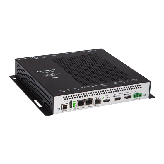
HDMI OUTPUT: 19-pin HDMI Type A connector, female; HDMI digital video/audio output (DVI compatible); 1, 2 Green LED indicates video signal transmission at the HDMI output HDMI INPUTS 1–2: 19-pin HDMI Type A connectors, female; HDMI digital video/audio inputs (DVI and Dual-Mode DisplayPort compatible); 1, 2 Two green LEDs, each indicates sync detection at the corresponding HDMI input AUDIO I/O: 5-pin 3.5 mm detachable terminal block;... - Page 10 NOTES: When a DM-NVX-35x decoder is connected to a DM-NVX-35x(C), DM-NVX- • 36x(C), or DM-NVX-E30(C) encoder, pressing the SETUP button on the decoder for less than 10 seconds displays the decoder IP address on the display connected to the HDMI output of the decoder. When a DM-NVX-35x encoder is connected to a DM-NVX-35x(C) decoder, •...
-
Page 11: Dm-Nvx-350C And Dm-Nvx-351C
DM-NVX-350C and DM-NVX-351C The following illustration shows the connectors, controls, and indicators that are available on the DM-NVX-350C and DM-NVX-351C. NOTE: The DM-NVX-350C and DM-NVX-351C contain the same connectors, controls, and indicators. For illustrative purposes, only the card named DM-NVX-350C is shown below. -
Page 12: Dm-Nvx-352C
HDMI OUTPUT: 19-pin HDMI Type A connector, female; HDMI digital video/audio output (DVI compatible) 1, 2 Green LED indicates video signal transmission at the HDMI output HDMI INPUTS 1–2: 19-pin HDMI Type A connectors, female; HDMI digital video/audio inputs (DVI and Dual-Mode DisplayPort compatible) 1, 2 Two green LEDs, each indicates sync detection at the corresponding HDMI input AUDIO I/O: 5-pin 3.5 mm detachable terminal block;... - Page 13 LAN 1: 8-pin RJ-45 connector, female; 100BASE-TX/1000BASE-T Ethernet port; Green LED indicates Ethernet link status; Amber LED indicates Ethernet activity LAN 2: SFP port; Accepts one Crestron SFP-1G Series SFP transceiver module; 1, 2 Green LINK LED indicates Ethernet link status; Green ACT LED indicates Ethernet activity HDMI OUTPUT: 19-pin HDMI Type A connector, female;...
-
Page 14: Configuration And Status
Configuration and Status This section provides information about configuring or viewing the following items using the web interface or SIMPL Windows as applicable: DMF-CI-8 chassis details • DM NVX Director™ virtual switching appliance • Encoding and decoding functionality • Automatic point-to-point connectivity •... -
Page 15: Dmf-Ci-8 Chassis Details
DMF-CI-8 Chassis Details NOTE: DMF-CI-8 chassis details apply to the DM NVX cards only and do not apply to DM NVX surface-mountable endpoints. A DM NVX card occupies a card slot in a DMF-CI-8 chassis. Information about the chassis can be viewed using the web interface or SIMPL Windows. Using the Web Interface To view DMF-CI-8 chassis information, click the Status tab and then click Chassis. -
Page 16: Dm Nvx Director Virtual Switching Appliance
DM NVX Director Virtual Switching Appliance If a DM NVX device is managed by a DM NVX Director™ virtual switching appliance, information about the appliance can be viewed using the web interface. To view DM NVX Director appliance information, click the Status tab and then click DM NVX Director. -
Page 17: Using The Web Interface
NOTES: When DM-NVX-35x(C) devices are used with DM-NVX-E30(C) and DM-NVX-36x(C) • encoders, the DM-NVX-35x(C) devices must be in Receiver mode. When DM-NVX- 35x(C) devices are used with DM-NVX-D30(C), DM-NVX-D80-IOAV, and DM-NVX- 36x(C) decoders, the DM-NVX-35x(C) devices must be in Transmitter mode. For a DM-NVX-35x surface-mountable endpoint, the SETUP button can be used to •... -
Page 18: Using Simpl Windows
Device Reboot Prompt For additional information, refer to the online help of the web interface. Using SIMPL Windows Using the top-level programming slot for the DM-NVX-35x(C) device, set the <DeviceMode> analog input join to the desired mode (Receiver or Transmitter). The default setting is Receiver. -
Page 19: Using The Web Interface
Using the Web Interface Enable or disable point-to-point mode by clicking the Settings tab and then clicking System Setup. In the Point-to-Point Control section, Point to Point Status indicates whether point-to- point mode is Active or Inactive. In the Point-to-Point Mode drop-down list, select either of the following: Auto: (Default setting) A 1000BASE-T port of a DM NVX encoder detects a •... -
Page 20: Stream Statistics
Stream Statistics Statistics can be displayed to indicate the number of packets received or transmitted, the number of dropped packets, and the bit rate of the received stream. To enable or disable or to reset stream statistics, use the web interface or SIMPL Windows as discussed in the following sections. -
Page 21: Multicast Ttl (Time-To-Live)
Multicast TTL (Time-to-Live) NOTE: Multicast TTL configuration applies to a DM-NVX-35x(C) device that is operating as a transmitter. Multicast TTL provides the ability to limit or extend the hop limit of a DM NVX stream that traverses routers. In IPv4 multicasting, routers have a TTL threshold assigned to each interface. -
Page 22: Using Simpl Windows
Settings Tab – Stream, Multicast TTL Configuration Using SIMPL Windows Configure multicast TTL as follows: Using the top-level programming slot: a. Trigger the <AutomaticInitiationDisabled> digital input join. b. Trigger the <Stop> digital input join. 2. In Slot-01: Stream Transmit, set the <MulticastTTL> analog input join to the desired value (1 to 255). -
Page 23: Differentiated Services Code Point (Dscp)
Differentiated Services Code Point (DSCP) NOTE: DSCP applies to a DM-NVX-35x(C) device that is operating as a transmitter. To implement Quality of Service (QoS), IP networks use the DSCP value. Within an IP packet header, the DSCP defines a value from 0 to 63 that maps to a certain traffic classification. -
Page 24: Automatic Routing Of Video Inputs
Settings Tab – Stream, Custom DSCP Automatic Routing of Video Inputs Automatic routing between video inputs can be enabled or disabled. When automatic routing is enabled, the device automatically routes the last connected input. To configure automatic routing, use the web interface or SIMPL Windows as discussed in the following sections. -
Page 25: Using Simpl Windows
Settings Tab – Routing, Automatic Input Routing Using SIMPL Windows Using the top-level programming slot for the DM NVX device, trigger the <AutomaticRoutingEnabled> digital input join to enable automatic routing. To disable automatic routing, trigger the <AutomaticRoutingDisabled> digital input join. For additional information, refer to the SIMPL Windows help file. -
Page 26: Automatic Display Control
Automatic Display Control For the DM-NVX-350, DM-NVX-351, and DM-NVX-352, the display device can be turned on or off automatically via RS-232, IR, or CEC (Consumer Electronics Control). For the DM-NVX-350C, DM-NVX-351C, and DM-NVX-352C, CEC can be used to automatically turn a display device on or off. To configure automatic display control: Click the Settings tab and then click Outputs. - Page 27 8. Do one of the following: If CEC is selected in step 4, enter the CEC command in the Power Off (No • Sync Detected) and Power On (Sync Detected) sections. If a custom command is desired, enter the desired command, and then select the desired terminator and format.
- Page 28 Settings Tab – Outputs, Automatic Display Power (Shown with DM NVX Device in Receiver Mode and CEC Interface Command Selected) 24 • DM-NVX-35x(C) Encoders/Decoders Product Manual – DOC. 7839L...
-
Page 29: Video Wall Processing
Video Wall Processing NOTE: Video wall processing applies to DM-NVX-35x(C) devices that function as receivers. Multiple DM-NVX-35x(C) receivers can be combined to configure a video wall composed of up to 64 individual displays (up to eight columns of displays by eight rows of displays). A separate DM-NVX-35x(C) device is required for each display. - Page 30 Settings Tab – Outputs, Video Wall Configuration 26 • DM-NVX-35x(C) Encoders/Decoders Product Manual – DOC. 7839L...
-
Page 31: Using Simpl Windows
Using SIMPL Windows Configure a video wall in Slot-06: HDMI OUT: Set the <VideoWallMode>, <Horizontal_Bezel_Compensation>, and <Vertical_Bezel_Compensation> analog input joins to the desired values. 2. Repeat step 1 for each DM-NVX-35x(C) receiver that connects to a display for inclusion in the video wall. For additional information, refer to the SIMPL Windows help file. -
Page 32: Using Simpl Windows
Settings Tab – Outputs, Underscan Configuration Using SIMPL Windows Adjust underscan in Slot-06: HDMI Out. Set the <Underscan> analog input join to the desired value. For additional information, refer to the SIMPL Windows help file. 28 • DM-NVX-35x(C) Encoders/Decoders Product Manual – DOC. 7839L... -
Page 33: User-Selectable Output Resolution
User-Selectable Output Resolution NOTE: User-selectable output resolution applies to a DM-NVX-35x(C) device that functions as a receiver. To select the desired output resolution, use the web interface or SIMPL Windows as discussed in the following sections. Using the Web Interface To configure the output resolution: Click the Settings tab and then click Outputs. -
Page 34: Using Simpl Windows
Settings Tab – Outputs, HDMI Output Resolution Configuration Using SIMPL Windows Configure the output resolution in Slot-06: HDMI Out. Set the <Resolution> analog input join to the desired value. For additional information, refer to the SIMPL Windows help file. 30 • DM-NVX-35x(C) Encoders/Decoders Product Manual –... -
Page 35: Maximum Color Depth And Color Space Mode
Maximum Color Depth and Color Space Mode Configure the maximum color depth (maximum bit depth supported by the output) and HDMI color space mode using the web interface or SIMPL Windows. Using the Web Interface To configure maximum color depth and color space mode: Click the Settings tab and then click Outputs. - Page 36 Settings Tab – Outputs, HDMI Output Maximum Color Depth and Color Space Mode 32 • DM-NVX-35x(C) Encoders/Decoders Product Manual – DOC. 7839L...
-
Page 37: Using Simpl Windows
Using SIMPL Windows Configure maximum color depth and color space mode in Slot-06: HDMI Out. Set the <MaximumColorDepth> analog input join to the appropriate value for the maximum bit depth supported by the output. Set the <ColorSpaceMode> analog input join to the desired value for the HDMI color space. - Page 38 Action Menu - EDID Management To select an EDID for the inputs: Click the Settings tab and then click Inputs. 2. Do either of the following: In the Global EDID section, set a global EDID for all inputs. • In the Inputs section, set the desired EDID for Input 1 and Input 2 by clicking •...
- Page 39 Settings Tab – Inputs, EDID Configuration Product Manual – DOC. 7839L DM-NVX-35x(C) Encoders/Decoders • 35...
-
Page 40: Adaptive Bit Rate
Adaptive Bit Rate NOTE: Adaptive bit rate applies to a DM-NVX-35x(C) device that functions as a transmitter. Adaptive bit rate functionality enables a DM NVX transmitter to automatically set the bit rate required for the input resolution of the stream; for example, the adaptive bit rate for a common resolution such as 1920x1080p@60Hz (1080p60) is automatically set to 400 Mbps. -
Page 41: Using Simpl Windows
Settings Tab – Stream, Advanced, Adaptive Bit Rate NOTE: When adaptive bit rate functionality is enabled, a bit rate cannot be set in the Bitrate drop-down list. Using SIMPL Windows Enable or disable adaptive bit rate functionality in Slot-01: Stream Transmit. Trigger the <AdaptiveBitrateModeEnable>... -
Page 42: Using The Web Interface
Using the Web Interface To configure subscriptions: Click the Settings tab. 2. Click Subscriptions and then do either of the following: In the Subscribed Streams section, manually add each transmitter that is to • be subscribed to the receiver or load one or more existing subscription lists (*.xml). -
Page 43: Using Simpl Windows
Settings Tab – Routing, Stream Routing For additional information, refer to the online help of the web interface. Using SIMPL Windows NOTE: Selection of the transmitters for subscription or selection of subscription lists can be performed using the web interface only. Manually select a subscribed transmitter for routing in Slot-1000: XIO Routing. -
Page 44: Daisy Chain
Daisy Chain DM-NVX-350(C) and DM-NVX-351(C) devices include three LAN ports (two RJ-45 LAN ports and one SFP LAN port). A DM-NVX-352(C) device includes two LAN ports (one RJ-45 LAN port and one SFP LAN port). The LAN ports can be used to daisy chain multiple DM NVX devices. -
Page 45: Switching Nonsubscribed Transmitters
Switching Nonsubscribed Transmitters To switch nonsubscribed transmitters in a daisy chain configuration, use the web interface or SIMPL Windows. Using the Web Interface To switch nonsubscribed transmitters: Click the Settings tab and then click Stream. 2. In the Advanced section: a. -
Page 46: 7.1 Surround Sound Audio
7.1 Surround Sound Audio DM-NVX-35x(C) devices support the lossless transport of 7.1 surround sound audio signals (including Dolby® TrueHD, Dolby Atmos®, DTS HD®, and DTS:X® audio signals) and uncompressed linear PCM. In receiver mode, the DM-NVX-350(C) and DM-NVX- 352(C) can receive both multichannel and 2-channel downmix signals from a DM-NVX- 351(C) or DM-NVX-363(C) transmitter, allowing either signal to be selected at the HDMI output while the 2-channel signal is automatically routed to the analog output. -
Page 47: Using The Web Interface
Using the Web Interface Configure DM NAX (AES67) audio by clicking the Settings tab and then configuring DM NAX (AES67) audio and routing: The DM NAX (AES67) Audio section varies depending on whether the DM NVX • endpoint is in Transmitter or Receiver mode. Refer to the “Configuring DM NAX (AES67) Audio for a DM NVX Transmitter”... - Page 48 Settings Tab - DM NAX (AES67) Audio Configuration in Transmitter Mode For additional information, refer to the online help of the web interface. 44 • DM-NVX-35x(C) Encoders/Decoders Product Manual – DOC. 7839L...
- Page 49 Configuring DM NAX (AES67) Audio for a DM NVX Receiver In the DM NAX (AES67) Audio section under the Settings tab, In the DM NAX (AES67) Transmit section, enter the multicast address and port • number. In the DM NAX (AES67) Transmit Advanced section, set the Auto Initiation toggle •...
- Page 50 Settings Tab - DM NAX (AES67) Audio Configuration in Receiver Mode 46 • DM-NVX-35x(C) Encoders/Decoders Product Manual – DOC. 7839L...
-
Page 51: Using Simpl Windows
Configuring DM NAX (AES67) Audio Routing To configure DM NAX (AES67) audio routing: Click the Settings tab and then clicking Routing. 2. In the Input Routing section: a. Set Audio Source to DM NAX (AES-67) Audio. b. Set Analog Audio Mode to Insert or Extract. c. -
Page 52: Dante And Aes67 Audio Embedding And De-Embedding
Dante and AES67 Audio Embedding and De-embedding NOTE: This section applies to the DM-NVX-352 and DM-NVX-352C only. Dante and AES67 support enables the selected audio source to be transmitted as a 2-channel Dante or AES67 source while another 2-channel Dante or AES67 audio stream is received from a Crestron DSP or other third-party device and combined with the video signal. -
Page 53: Using The Web Interface
Using the Web Interface Configure Dante or AES67 audio by clicking the Settings tab and then configuring stream and routing settings: In the Stream section, fill in the appropriate information in the Dante/Aes-67Name text box by entering the name of the Dante module that will be used in the Dante Controller. -
Page 54: Using Simpl Windows
2. In the Routing section: a. Set Audio Source to Dante/AES-67 Audio. b. Set Analog Audio Mode to Insert or Extract. c. Set Dante/AES-67 Transmit Audio Source to the desired audio source for the Dante or AES67 output. Settings Tab – Routing, Dante or AES67 Configuration For additional information, refer to the online help of the web interface. -
Page 55: Analog Audio Input Or Output
Analog Audio Input or Output Analog audio can be configured as either an input or an output: As an input on a DM-NVX-35x(C) device that functions as a transmitter, analog • audio can be configured as the audio source and be inserted into a network video stream and the HDMI output. - Page 56 (Applicable only when Audio Mode is set to Insert) Set Audio Source to • Analog Audio. Settings Tab – Routing, Analog Audio Source Configuration 2. (Applicable only if Analog Audio Mode is set to Extract) Under the Settings tab: 3. In the Outputs section: Click Outputs and then click the Edit button.
- Page 57 Settings Tab – Outputs, Analog Audio Volume Configuration For additional information, refer to the online help of the web interface. Product Manual – DOC. 7839L DM-NVX-35x(C) Encoders/Decoders • 53...
-
Page 58: Using Simpl Windows
Using SIMPL Windows NOTE: To insert or extract analog audio, use the web interface. Using the top-level programming slot for the DM NVX device, set the <AudioSource> analog input join to Analog Audio if analog audio is to be inserted into a network video stream or the HDMI output. -
Page 59: Using Simpl Windows
Settings Tab – Routing, Breakaway Audio Configuration Using SIMPL Windows Using the top-level programming slot for the DM NVX device, set the <AudioSource> analog input join to one of the following: Input 1 • Input 2 • Analog Audio • Primary Stream Audio •... -
Page 60: Usb 2.0 Routing
USB 2.0 Routing DM-NVX-35x(C) devices support the extension of USB 2.0 signals. A DM-NVX-35x(C) device provides a USB 2.0 DEVICE port and a USB 2.0 HOST port; however, both ports cannot be used simultaneously. The DEVICE port on one DM NVX device can be connected to a computer or other host device. - Page 61 3. In the USB Mode drop-down list, select Local for the local extender or Remote for a remote extender. 4. In the Transport Mode drop-down list, select either of the following: Layer 2: Enables Layer 2 transport of USB 2.0 data. This mode is compatible •...
- Page 62 8. (Applicable to Remote USB mode only) Do either of the following: In the Remote Device ID text box for Layer 2 transport, enter the MAC • address of the local extender. In the Remote Device ID text box for Layer 3 transport, enter the IP address •...
-
Page 63: Using Simpl Windows
Using SIMPL Windows Using SIMPL Windows, configure USB routing in Slot 30: USB: Determine the DM-NVX-35x(C) devices that are to be paired: One DM NVX device functions as the local extender (LEX); that is, the • DEVICE port connects to a computer or other host device. For Layer 2 transport, up to seven DM NVX devices can function as remote •... - Page 64 On the LEX device, the <UsbRemoteDeviceId_F> and <UsbRemoteDeviceId2_F> through <UsbRemoteDeviceId7_F> serial output joins report the MAC address of each REX device to which the LEX device is to be paired. For Layer 3 transport: • a. Copy the IP address (UsbLocalDeviceIpAddress) of the LEX device into the <UsbRemoteDeviceIpAddress>...
-
Page 65: Network Port Selection
Network Port Selection Network port selection enables network traffic to be managed and segregated based on traffic type. Internal VLANs are used to route different traffic types to specific external Ethernet ports, which are assigned to the various traffic types. AES67 or Dante audio can be separated from the primary video and control network resulting in a dedicated audio network. -
Page 66: Device Mode Locking
Settings Tab, Port Selection Device Mode Locking Device mode locking controls whether the SETUP button on a DM-NVX-35x and the DMF-CI-8 front panel can be used to change the operating mode of the DM-NVX-35x and DM-NVX-35xC devices, respectively. The operating mode determines when the DM-NVX-35x(C) device functions as a receiver or transmitter. -
Page 67: Crestron Xio Cloud Service Connection
Settings Tab – System Setup, Device Mode Lock Configuration For additional information, refer to the online help of the web interface. Crestron XiO Cloud Service Connection The Crestron XiO Cloud® service allows supported Crestron devices across an enterprise to be managed and configured from one central and secure location in the cloud. Connection to the XiO Cloud service can be enabled or disabled using the web interface. -
Page 68: Enterprise-Grade Security
Enterprise-Grade Security DM NVX devices incorporate advanced security features such as user and group authentication management, IEEE 802.1X authentication, AES-128 content encryption, PKI authentication, TLS (Transport Layer Security), SSH (Secure Shell), and HTTPS (Hypertext Transfer Protocol Secure). Configure user and group authentication and IEEE 802.1X authentication using the web interface. -
Page 69: Ieee 802.1X Authentication
IEEE 802.1X Authentication IEEE 802.1X is a network standard designed to enhance the security of wireless and wired LANs. The standard defines how to provide authentication for devices trying to connect to other devices on the LAN. To manage trusted certificate authorities, go to the Action menu in the upper-right corner of the web interface and select Manage Certificates. - Page 70 To configure IEEE 802.1X authentication in the web interface, click the 802.1X Configuration tab. For detailed information, refer to the online help of the web interface. 802.1X Authentication Tab 66 • DM-NVX-35x(C) Encoders/Decoders Product Manual – DOC. 7839L...
-
Page 71: Automatic Firmware Update
Automatic Firmware Update A DM NXV device can be automatically updated with the latest firmware at scheduled intervals. To configure automatic firmware update: Using the Crestron Auto Update Tool, generate a manifest file (*. mft). The file is placed on an FTP (File Transfer Protocol) or SFTP (Secure File Transfer Protocol) server. - Page 72 Clicking Update Now causes the firmware to be updated at the current time; however, the schedule that is set in step 2d above remains in effect. Settings Tab – System Setup, Auto Update 68 • DM-NVX-35x(C) Encoders/Decoders Product Manual – DOC. 7839L...
-
Page 73: Igmp Snooping
IGMP Snooping A DM NVX device sends IGMP join and leave messages. NOTE: DM NVX devices support IGMPv2 and IGMPv3 only. IGMPv1 is not supported. The IGMP snooping support version (v2 or v3) is configurable in the web interface. The desired version can be selected under the Settings tab in the System Setup – Network Interface section. - Page 74 NOTES: DM NVX devices do not support random-timer and source-specific queries. • As a host, a DM NVX device configured for support of IGMPv3 is compatible with a • network switch (IGMP querier) that is configured for IGMPv2. IGMP snooping switches build forwarding lists by listening for and, in some cases, intercepting IGMP messages.
- Page 75 If the network switch supports IGMP fast leave, enable the configuration at the • port, global, or VLAN level. If the network switch supports PIM snooping, enable the configuration to prevent • flooding IP multicast traffic toward multicast router (mrouter) ports. Product Manual –...
-
Page 76: Troubleshooting
Troubleshooting The following table provides troubleshooting information. If further assistance is required, contact a Crestron customer service representative. DM NVX Encoder/Decoder Troubleshooting PROBLEM POSSIBLE CAUSE(S) CORRECTIVE ACTION 4K60 4:4:4 2-channel non-HDR or The display device is not Configure the display device properly. 4K60 4:4:4 2-channel HDR video configured properly. - Page 77 DM NVX Encoder/Decoder Troubleshooting (Continued) PROBLEM POSSIBLE CAUSE(S) CORRECTIVE ACTION The analog audio input is not The analog audio mode is set to Set the analog audio mode to insert functioning. extract audio. audio. An incorrect audio source is Set the audio source to analog audio. selected.
- Page 78 If, for any reason, the factory default settings of a DM NVX device must be restored, do one of the following: In the Action menu located in the upper-right corner of the web interface, click • Restore. From the Tools menu in the Crestron Toolbox software, select Text Console and •...
-
Page 79: Appendix. Device Discovery
Appendix. Device Discovery A DM NVX device can be discovered on the network by using the Device Discovery Tool within the Crestron Toolbox software. To discover a DM NVX device: Open the Crestron Toolbox software. 2. From the Tools menu, select Device Discovery Tool. NOTES: You can also access the Device Discovery Tool by clicking the Device Discovery •... - Page 80 Device Administration Login Page 6. Enter the user name and password. The default user name and password are admin both NOTE: The user name and password are case sensitive. 7. Click Sign In. The web interface of the DM NVX device opens. For additional information, refer to the online help of the web interface.
- Page 81 This page is intentionally left blank. Product Manual – DOC. 7839L DM-NVX-35x(C) Encoders/Decoders • 77...
- Page 82 Crestron Electronics, Inc. Product Manual – DOC. 7839L 15 Volvo Drive, Rockleigh, NJ 07647 Tel: 888.CRESTRON 7/9/2021 Fax: 201.767.7576 Specifications subject to www.crestron.com change without notice.
Need help?
Do you have a question about the DM NVX Series and is the answer not in the manual?
Questions and answers