
Subscribe to Our Youtube Channel
Related Manuals for Kval ON-3V


Summary of Contents for Kval ON-3V
- Page 1 Operation Manual Published: February 2, 2021 Innovation, Quality & Honesty ON-3V Door Lift System...
- Page 2 Proprietary Notice This Manual is confidential and contains proprietary information and intellectual property of KVAL Inc., and is to be used solely by Customer as an operating manual for KVAL Inc. machines. Neither this Manual nor any of the information contained herein may be reproduced or disclosed under any circumstances without the express written permission of KVAL Inc.
- Page 3 KVAL ON-3V Operation Manual Your Feedback is Welcome: NOTE: KVAL ON-3V Operation Manual...
- Page 4 KVAL ON-3V Operation Manual...
-
Page 5: Table Of Contents
The Door is Fed into the Stacker ............2-4 The Door is moved to the Stacking Area ..........2-5 Move Stacked Doors out of Staging Area..........2-5 Powering Operations for the ON-3V ........2-6 How to Power Up the ON-3V..............2-6 Home the ON-3V ..................2-7 How to Power Shut Down the ON-3V...........2-7... - Page 6 About the Diagnostic Screen ........... 2-23 Diagnostic Screen................2-23 Description of the Light Tower ..........2-24 Tour of the ON-3V Chapter 3 Operator’s Tour of the ON-3V ..........3-2 Identification of Assemblies on the ON-3V ...........3-2 Feeder ....................3-2 Stacker....................3-3 Identification of Assemblies (Front View)..........3-4 About the Feed Table...............
- Page 7 The Light Tower ..................3-15 About the Nodes .................3-15 Graphical Sample of Node Connections and Power Distribution ..3-16 IT Administration ..............3-17 About the ON-3V Computer..............3-17 Connections on the PLC..............3-17 Appendix: About Switches and Sensors ........3-18 KVAL ON-3V Operation Manual...
- Page 8 Table of Contents KVAL ON-3V Operation Manual...
-
Page 9: Chapter 1 At A Glance
Introduction to the ON-3V CHAPTER 1 This chapter provides an overview of the KVAL ON-3V system and important safety information to follow when operating the machine. Chapter 1 at a Glance Section Name Summary Page This section provides an overview of the ON-3V. It... -
Page 10: Overview Of The On-3V
'Call Door' switch or automatically fed when the next machine in the line is ready to receive a door. Cycle time is approximately 20 seconds. The ON-3V can lift and feed flush doors and up to 4ft wide by 8ft high. The door is lifted via a vacuum system which utilizes two vacuum pads to lift the unit. -
Page 11: About This Manual
Overview of the ON-3V About this Manual Operation Manual Chapter Title Description Introduction Descriptions of Machine Line and Safety Information. Operation of the Descriptions of how to power Machine machine line, and operator inter- face user screens. Tour of ON-3V Identification and descriptions of the ON-3V- machine assemblies. -
Page 12: Safety First
Safety First! Safety First! Failure to do so can result in dam- age to equipment and/or serious injury to personnel. Safety Sheet Sign-Off Sheet Safety Terminology of Labels DANGER WARNING CAUTION Safety Guidelines Training... - Page 13 All cylinders on machine are under high pressure and can be very dangerous when activated. Before performing any mainte- nance or repairs on this machine turn off the main air disconnect. Lockout and tagout this connection. See “Lockout Tagout Procedure” on page 1-9. KVAL Manual...
- Page 14 Safety First! Electrical still power on the top side of the disconnect switch must be installed at all locations Before Conducting Maintenance Laser Warnings...
- Page 15 Safety First! Compliance with Codes and Regulations Other Hazard Control Action Report a Hazard STOP Before You Report an Accident Follow Your Company’s Safety Procedures...
-
Page 16: Lockout-Tagout Guidelines
O..OFF! Shut off all power sources and isolating devices P..Place lock and tag E..ENERGY: Release stored energy to a zero-energy state R ..Recheck controls and test to ensure they are in the “OFF” state KVAL Manual... -
Page 17: Lockout Tagout Procedure
Turn Switch to the Lock and Tag out Insert Lock into hole. OFF position Note: When multiple people are working on the machine, each person needs to have a lock on the handle in the extra holes provided. KVAL Manual... -
Page 18: Lockout Tagout Air Supply
The lock and tag can now be removed (only by the person(s) who placed them), and the machine can be re-energized. The tags must be destroyed and the locks and keys returned to the lockout center. KVAL Manual 1-10... -
Page 19: Zero-Energy To Start-Up
Replace Guards Replace all equipment guards. If part of equipment cannot be properly adjusted after start-up with guard on, contact the KVAL Service team. See “Getting Help from KVAL” on page 1-13. Check Controls Confirm that all switches are in the “OFF”... - Page 20 Be sure to follow the P-R-O- P-E-R lockout/tagout procedures, and that those around you do also. Close the Cage Gate Verify all cage gates are securely closed. Ensure all safety protocols are in effect. KVAL Manual 1-12...
-
Page 21: Getting Help From Kval
Getting Help from KVAL Getting Help from KVAL Air Driven Machines Pre -2019 Machines, look for the brass plate. 1-13... - Page 22 • With what equipment is the unit interfaced? • What was the application? • What was the system environment (temperature, spacing, contaminants, etc.)? Call KVAL customer support for a Return Material Authorization (RMA). When you call: • Have the packing slip or invoice numbers available.
- Page 23 Getting Help from KVAL Page Intentionally Left Blank KVAL Manual 1-15...
-
Page 24: Safety Sign-Off Sheet
Note: It is recommended you make a copy of this sheet for new operators. If a copy is needed, you may download a PDF at the KVAL website (http://www.kvalinc.com). You may also contact our Service Department at (800) 553-5825 or email at service@kvalinc.com. - Page 25 Operation of the ON-3V CHAPTER 2 This chapter describes components, assemblies, and the user interface of the KVAL ON-3V System The content is geared to help operators understand the basic operation of the machine. Included are instructions to calibrate the machine and process a door.
-
Page 26: On-3V: Feeder Process Summary
ON-3V: Feeder Process Summary ON-3V: Feeder Process Summary Kval ON-3V Door Feeder Kval Note: ON-V3, Note: Note: Chapter 3 Load the Doors into the Staging Area and Program Door Process Request Access Button Load Doors * Power Up * Load Doors... -
Page 27: The Door Is Moved To The Roll Table
ON-3V: Feeder Process Summary The Door is moved to the Roll Table raise the door. Lifting Pads If programmed to rotate, the lift will rotate the doors 180 degrees to match the Note: correct swing (LH or RH). moves the door over the... -
Page 28: On-3V: Stacker Process Summary
Kval Kval For power-up of the machine, For power-up of the machine, see “Powering Operations for the ON-3V” on see “Powering Operations for the ON-3V” on Note: Note: page 2-6. page 2-6. -
Page 29: The Door Is Moved To The Stacking Area
ON-3V: Stacker Process Summary The Door is moved to the Stacking Area raise the door. (Some options may have the rotate) Lifting Pads moves the door over the Boom Stacking Area The next door is fed in and process repeats. -
Page 30: Powering Operations For The On-3V
Powering Operations for the ON-3V Powering Operations for the ON-3V ON-3V. How to Power Up the ON-3V Note: Control Circuit Note: Note: 990 machine manual Start Machine Buttons Ready to Home Control Circuit Start Machine Note: Stacker Controls may contain Machine Power button in place... -
Page 31: Home The On-3V
Powering Operations for the ON-3V Note: Home the ON-3V must Home Machine Main Control Screen The Machine is ready to Work How to Power Shut Down the ON-3V Stop Buttons Note: Stop Button Control Circuit Note:... -
Page 32: Shut Down And Recovery
Powering Operations for the ON-3V Exit Application Button Control Circuit Shut Down and Recovery Note:... -
Page 33: Process To Feed A Door
Process to Feed a Door Process to Feed a Door Note: ON-3V. Snapshot Request Access In. Request Access Button Load Doors. Request Access Out. Reset Button. Request Access Button Home Machine. Reset Button Select Rotation. Enter Qty. of Doors. 6. Home Enter Door Process Information. -
Page 34: Process To Stack A Door
Process to Stack a Door Process to Stack a Door Ensure factory air is present at the ON-3V and the other machines. Power the all the machines in the line. Note: Power up the See “Powering Operations ON-3V. Snapshot for the ON-3V” on page 2-6. -
Page 35: Staging Area Controls
Pause/Resume Button cess cycle. To resume the process, push the button again. Emergency Stop Press the Emergency button to stop machine. Will maintain clamp and lift. To restart machine, see “Emergency Stop” on page 2-11. KVAL Manual 2-11... -
Page 36: Breaking The Safety Curtain
Breaking the Safety Curtain Breaking the Safety Curtain Light Curtain or Laser Safety Scanner Note: Light Curtain Breaking of any beam stops the machine. Press the Reset Button to Con- tinue Processing the Doors. Receiver Emitter Safety Laser Scanners Breaking of the beam stops the machine. -
Page 37: Summary Of The Interface
At this screen, move the Gantry and Table Assemblies manually. See “About the Feeder Manual Control Screen” on page 2-21. Diagnostic Screen At this screen, the feedback codes from the machine are displayed. See “About the Diagnostic Screen” on page 2- KVAL Manual 2-13... -
Page 38: Stacker Machine Control
Door Stops on the table. “About the Stacker Manual Control Screen” on page 2- Diagnostic Screen At this screen, the feedback codes from the machine are displayed. See “About the Diagnostic Screen” on page 2- KVAL Manual 2-14... -
Page 39: Universal Controls
Universal Controls Universal Controls Machine Feedback Jump Buttons: Select to move to desired screen Machine Feedback Home Machine: Reset Button: This button starts the home sequence on the machine, which scans to find a physical reference If a fault occurs that cannot be cleared, select the point on the frame. -
Page 40: About The Controls
Universal Controls About the Controls Park Gantry: Pause/Resume: Select to place the gantry in the rest position. The Gantry will fin- Select the Pause button to ish task and if in process. The hold process of the door. Gantry will move over the table Select again to Resume from and lower to the table position. -
Page 41: About The Feeder Main Screen
About the Feeder Main Screen About the Feeder Main Screen Feeder Main Screen About the Main Control Menu Queue Door Quantity: Select and enter the number of doors to be processed. Note: Entering “0” into the Quantity box puts the machine in Full Stack Mode. -
Page 42: Summary Of The Rotate Functions
About the Feeder Main Screen Summary of the Rotate Functions: Rotate Off: Rotate All: Rotate Alternate: Rotate Queue: More Pages 2-18... -
Page 43: About The Stacker Main Screen
About the Stacker Main Screen About the Stacker Main Screen Stacker Main Screen Door Length Door Length Confirm Manual Data Door Stop Feed Through Stop 1 Stop 3 Stop 2 Door Length Buttons: Door Length Box: Feed Through Button: Select to a Length button bypass the Displays the Length Select to bypass stacking auto length. -
Page 44: Stop Location
About the Stacker Main Screen Stop Location The Door Stops are located at the end of the Stacker table. Door Stop 1 Door Stop 2 Door Stop 3 Stop Location FIGURE 2- 2. KVAL Manual 2-20... -
Page 45: About The Manual Operation Screens
About the Manual Operation Screens About the Manual Operation Screens Manual Manual Mode About the Feeder Manual Control Screen Feeder Table Buttons: Select the desired button to control Gantry: Select the desired button to the feed through of the door. control the Gantry. -
Page 46: About The Stacker Manual Control Screen
About the Manual Operation Screens About the Stacker Manual Control Screen Feeder Table Buttons: Select the desired button to control the feed through of the door. Gantry: Select the desired button to Select to manually engage Stop 1, Stop 2, or Stop 3 control the Gantry. -
Page 47: About The Diagnostic Screen
About the Diagnostic Screen About the Diagnostic Screen Diagnostic Screen Diagnostics Screen FIGURE 2-5. 2-23... -
Page 48: Description Of The Light Tower
Description of the Light Tower Description of the Light Tower Light Position Category Descriptions OFF (Clear): Machine not in operation. White: Initializing 1 Flash: Waiting for all systems to initialize Red: Machine Error Solid: General Error • 1 Flash: EtherCat Device not Ready to Run •... - Page 49 Page Descriptions of the operation of the parts and page 3-2 Operator’s Tour assemblies of the machine. • Top View and Front of on ON-3V page 3-2 • Feeder Table page 3-5 • Boom and Lift Assembly Descriptions page 3-7 •...
-
Page 50: Operator's Tour Of The On-3V
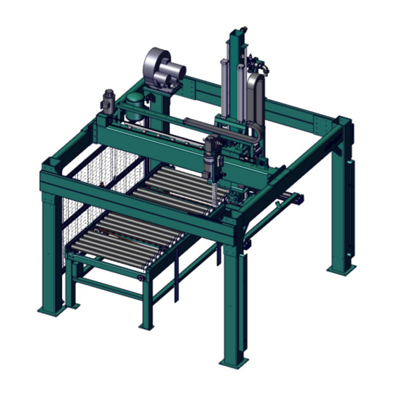
Operator’s Tour of the ON-3V Operator’s Tour of the ON-3V Identification of Assemblies on the ON-3V Feeder Boom and Lift: Operators Controls: Vacuum Blower Motor: See “Boom and Lift Assembly See “Staging Area Controls” See “Vacuum System” on Descriptions” on page 3-7. -
Page 51: Stacker
Operator’s Tour of the ON-3V Stacker The Stacker brings in the doors and stacks them for removal to the next process step. The Stacker contains the same assemblies as a , see Figure 3- 1 on page 3-2. Feeder The Stacker may include pop stops to adjust to incoming doors. -
Page 52: Identification Of Assemblies (Front View)
Operator’s Tour of the ON-3V Identification of Assemblies (Front View) Vacuum Blower Motor Boom And Lift Controllers: Request Access Light Curtain: Safety Staging Area Feed Table Front View of ON-3V FIGURE 3- 3. KVAL Manual... -
Page 53: About The Feed Table
When cross feed cylinders re retracted, door is fed into table. Pop-Up Cylinders: (x4) Cross Feed Belts (X2): Elevates rollers to move Moves door to the fence. door to the fence Machine Table Assembly Locations FIGURE 3- 4. KVAL Manual... -
Page 54: About The Stacker Table
The sensors are triggered by door length to act like a stop for the triggered door size. Feed Rollers: Moves door In Photo Sensor: Photo Sensor: Door Stops Mid Machine and at Fence Photo Sensor: Infeed Stacker Machine Table Assembly Locations FIGURE 3- 5. KVAL Manual... -
Page 55: Boom And Lift Assembly Descriptions
Rotate Gear (Opt): Rotates Lift Foam Lifters: assembly 0 to 180 ° Suction powered foam lifters. Lifts doors and moves doors. Feeder: Door staging area to feed table. Description of Boom Components FIGURE 3- 6. KVAL Manual... -
Page 56: Operators Station
Request Access buttons located on the Staging area frames. Control Location Options: Depending on customer desired options, the con- trols may be located at the ON-3V. The controls are the same. Operator Station Example FIGURE 3- 7. -
Page 57: Staging Area Controls
To resume the process, push the button again. Emergency Stop: Press the Emergency button to stop machine. Will maintain clamp and lift. To restart machine, see “Shut Down and Recovery” on page 2-8. Staging Area Controls FIGURE 3- 8. KVAL Manual... -
Page 58: Vacuum System
The vacuum system is composed of modular components to lift doors from a door the stacking area to the feed table. The vacuum is controlled by Kval operation software. The main compo- nents include a high efficient vacuum blower/motor, control solenoids, connectors, and grabbing suction foam pads. -
Page 59: Assist Chain System
Assist Chain System Assist Chain System Caution: Air Assist Chain System Vertical Lift Assembly Lockout Tagout Procedures About the Air Assist Chain System Air Assist Chain System Assist Cylinders Buffer Tank Lift Chain Chain Assist System FIGURE 3- 10. 3-11... -
Page 60: About The Safety Curtain And The Safety Laser Scanner
About the Safety Curtain and the Safety Laser Scanner About the Safety Curtain and the Safety Laser Scanner Light Curtain or Safety Laser Scanner Note: Important: About Bar Type Sensors Breaking of the beam stops the machine. Press the Reset Button to Continue Processing the Doors. -
Page 61: About Safety Laser Scanners
About the Safety Curtain and the Safety Laser Scanner About Safety Laser Scanners Breaking of the beam stops the machine. Press the Reset Button to Continue Processing the Doors. General Information of the Scanner Note: TABLE 3-1. Number Function Color Off State On State Green... -
Page 62: About The Main Electrical Panel
• Contains VFD’s (Variable Frequency Drives). Electrical Outlet Thermal Resistor 24VDC Supplies Relays 24 VDC Terminals High Voltage Input Contactors Transformer Fuses Thermal Resistors VFD Feeder Motors Out Feed Up/Down Carriage Vacuum Feeder Electrical Panel FIGURE 3- 12. KVAL Manual 3-14... -
Page 63: The Light Tower
About the Main Electrical Panel The Light Tower Note: About the Nodes Note: PLC Interface Inputs and Outputs Top Ethernet cable is PLC Bottom Ethernet goes to Cutter Node Interconnect Bar Sample of a Frame Node FIGURE 3-13. 3-15... -
Page 64: Graphical Sample Of Node Connections And Power Distribution
About the Main Electrical Panel Graphical Sample of Node Connections and Power Distribution The ON-3V frame node is located on the machine boom. Power Power Distrib- Frame Node uted to Points in the machine Node Location FIGURE 3- 14. KVAL Manual... -
Page 65: It Administration
IT Administration IT Administration About the ON-3V Computer Connections on the PLC Smart Power Supply RJ45 to CPU Module and EtherCat Intranet Interface to Servos Compact Battery Interface to DVI/USB Module Flash Card Frame to User Interface Connections on the Controller FIGURE3- 15. -
Page 66: Appendix: About Switches And Sensors
Appendix: About Switches and Sensors Appendix: About Switches and Sensors Photo Electronic Detector Photo Eye Detectors no object One Package Proximity Sensor 3-18... - Page 67 The Limit Switch is activated by an assembly moving a switch arm. • .Depending on the model of limit switch, the amount of “pre-travel” (amount of movement from the arms resting position) is either 5 or 20 degrees before the limit switch actuates (Clicks). Switch Arm KVAL Manual 3-19...
- Page 68 Appendix: About Switches and Sensors KVAL Manual 3-20...
- Page 69 17 zero-energy start-up remote connection 17 RJ45 to intranet 17 clean up 11 intranet inspect 11 RJ45 connection 17 LCD display smart power supply 17 lockout and tagout Guidelines 11 lockout procedure 9 main electrical panel description 14 Kval ON-3V...
- Page 70 Index Kval ON-3V...
- Page 72 Contacting KVAL Customer Service Phone and Fax: Mailing address: In the U.S and Canada, call (800) 553-5825 or fax Customer Support Department (707) 762-0485 Kval Incorporated Outside the U.S. and Canada, call (707) 762-7367 825 Petaluma Boulevard South or fax (707) 762-0485 Petaluma, CA 94952 Email: service@kvalinc.com...
Need help?
Do you have a question about the ON-3V and is the answer not in the manual?
Questions and answers