Table of Contents
Advertisement
Quick Links
Advertisement
Table of Contents

Subscribe to Our Youtube Channel
Related Manuals for Newall DP900

Summary of Contents for Newall DP900
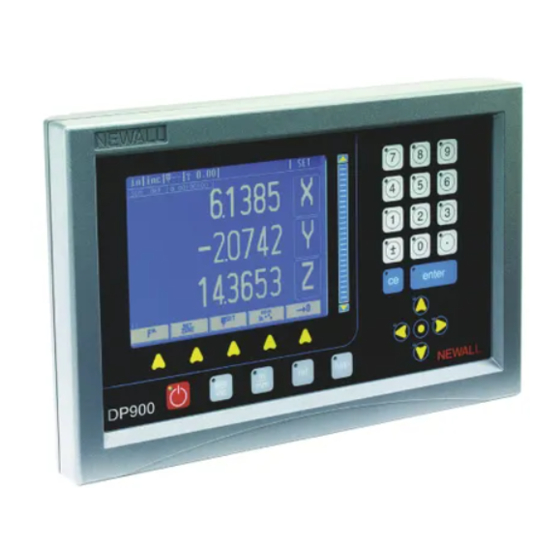
- Page 1 Digital Readout Display DP900 Manual...
-
Page 2: Table Of Contents
Contents Introduction ......1 Key beep enable ......9 Front . - Page 3 Contents Mill functions ......21 Generic functions ......33 Bolt hole .
-
Page 4: Introduction
USB ‘B’ type Power on/off The DP900 is available with 2, 3 or 4-axes of encoders. The 4th, 'W', axis can be a Newall Spherosyn/Microsyn (analog) or an RS422 TTL diferential (digital) depending on the specific unit. You can set the RS422 TTL W-axis to show linear or angular measurement. -
Page 5: Screen Layout
Using the Help system navigation keys. The DP900 has a comprehensive context-sensitive help system. • You use the up and down navigation keys to move between different The [help] key takes you to context-sensitive help so you can find the fields within forms or list boxes. -
Page 6: Information Bar
Func ( ). You use this to display a machine-specific functions list. This The top of the DP900 graphical display shows the current user basic is explained in more detail in Lathe functions, Mill functions and Generic display options. It also shows the current Feed-rate, Tool selection and functions. -
Page 7: Other Functions
If you choose to save the job later find information on tap sizes and clearance drills in both imperial and then you can do so. The DP900 can save and recall up to 20 programs for metric formats. -
Page 8: Front Panel Dedicated Keys
You should make a permanent mark on the machine when setting This temporarily turns off the display and keyboard. All other settings are reference points. If the axis has been moved while the DP900 power was preserved. Encoder movement is still monitored while in sleep mode. -
Page 9: Alphanumeric Keypad
Navigation keys position is updated, and Digifind is complete. The DP900 has four arrow keys that you use to navigate around the screen. In this manual these are referred to as the navigation keys. These Before you can use Digifind to find the Machine reference, you need to keys are as follows: define it in Setup mode >... -
Page 10: Specifications
Specifications Specification s Model Spherosyn/Microsyn** TTL* Mains supply 90…265V AC DP9004111DA X, Y, Z 50…60Hz Fuse ratings T800mA *TTL = 5V A quad B differential (RS422) 20mm length Power consumption Operating temperature 0°C to 45°C Storage temperature -20°C to 70°C Relative humidity Max 85% non-condensing Dimensions... - Page 11 Specifications **Spherosyn/Microsyn: 2V, 1kHz, phase analog 360 degrees per ball pitch Phase Transmitted Shift (drive) signal Time Received Signal Phase change of 90° relating to ¼ of a pitch or 1/8 inch (3.175 mm) for Spherosyn.
-
Page 12: Setup Mode
When you enable the Zero Approach Beep, bars appear under the axis Setup m ode This chapter describes how to setup the DP900. numbers to clearly indicate the direction and relative position of the axis to Use the right navigation key to scroll through the soft keys until the Setup zero. -
Page 13: Select Axis
Setup mode For Newall encoders the Type is 'N' and for RS422 encoders the type is Resolution Display Spherosyn Microsyn 10 Microsyn 5 'Q'. Newall encoders provide a count that represents the absolute position on the ball element within the scale in bits. (1-bit is 1/10000th of a ball 5 µm... - Page 14 Setup mode Set the Absolute Datum using Digifind. Press the slider bar close to Reference Mode. This defines which reference mode to select, Internal or the particular axis to set the datum. For the W-axis, the DRO goes to External. For Internal mode, the DRO uses the encoder reference mark the next screen automatically once it senses the reference output for referencing.
-
Page 15: Machine Model
Setup mode Zero App. Tolerance. This is similar to the zero approach tolerance for The default setup settings are: the linear mode, except that the setting is in angular mode. The default No. of Axis value is 0. You should save the changes that you make in the Setup mode using Sleep Mode Time Save and Exit. - Page 16 DRO system. You do this by comparing The difference between the laser / dial indicator reading and the the movement of the Newall reader head to the position reading shown on reading on the DRO display is your machine error.
-
Page 17: Calibrate Axis
The DP900 has an automatic facility to calculate the linear error correction scalar. Calibration parameters are found under Setup mode > Select axis. There are two options: All displayed values are in mm, regardless of whether the DP900 is set to inch or mm mode. • Calibrate axis Move to the start position. -
Page 18: Segmented Compensation
Starting point - zero Segmented compensation Error On the DP900 each axis can have up to 50 segments of compensation. Compensation is provided linearly between the segment points. Travel The values for segmented error compensation are calculated using a simple semi-automated procedure. - Page 19 Setup mode Press {auto}. Press {edit}. The message ‘Homing...’ appears on the screen, and the DP900 Enter a value for the Observed Value. automatically finds the Starting Point. Enter a value for the True Value. Press the slider bar next to the axis you are calibrating.
-
Page 20: Basic Functions
Inch and mm Basic functions This chapter describes the basic functions of the DP900. The DP900 has a dedicated key (the [inch/mm] key) to switch the The basic functions are as follows: positional displays between imperial (inch) and metric (mm) •... -
Page 21: Example
The values displayed do not affect the axis positions and the axis datum is Referencing restored when you exit the Preset mode function. With the DP900 you can set two different reference points (home) for each Example axis. Machine reference (M/C Ref). -
Page 22: Finding The Machine Reference
Digital encoder reference The screen displays the message 'Homing...'. If your DP900 is fitted with a 4th axis RS422 quadrature encoder then the Ensure the axis marks are aligned correctly by moving the axis. reference is taken directly from the scale. These encoders can have one or more reference marks and you should be aware of this and where the Press the axis key slider bar. -
Page 23: Calculator
Basic functions The Arc and Bolt Pattern features are not supported by the zoom in/out The result displayed is '3104.4549'. You can use this result for other feature. operations. Trigonometric Functions. (sin, cos, tan, sin , cos and tan Calculator These operate on a single operand. -
Page 24: Mill Functions
A plane is defined by a pair or orthogonal axes. The three available planes are X-Y, X-Z and Y-Z. By default the DP900 selects the X- Exits from the Function List. Y plane as this is the most common. -
Page 25: Line Hole
Mill functions • Depth (Requires 3-axis DRO). Line hole This function is used to calculate the locations of holes in a linear pattern. • Plane (X-Y, X-Z or Y-Z). It is also known as Linear Bolt Hole. The following parameters are When you have entered all the parameters: required: Press... -
Page 26: Grid
Mill functions Grid Pitch 2 This function is used to calculate the location of holes in a grid pattern. The following parameters are required for this function: Pitch1 • Pattern starting point coordinates. • Angle. • Pitch distance in axis '1'. Angle •... -
Page 27: Arc Contouring
Mill functions When you have entered all the parameters: Enter a name for your pattern, and press You return to the parameters screen. Press This opens the Data Entry screen. Press This opens a graphical display showing the arrangement of the Enter a name for your pattern, and press holes. -
Page 28: Pocket
Mill functions When you have entered all the parameters: end point 7 end point centre 7 and 1 2 and 6 and 6 Press type 1 type 4 This opens the Data Entry screen. type 7 Axis 1 Enter a name for your pattern, and press type 6 X or Y You return to the parameters screen. -
Page 29: Slot
Mill functions When you have entered all the parameters: • Depth. • Plane (X-Y, X-Z or Y-Z). Press When you have entered all the parameters: This opens the Data Entry screen. Press Enter a name for your pattern, and press This opens the Data Entry screen. -
Page 30: Polar Coordinates
Mill functions Polar coordinates Turns this mode off. This switches the DRO back to the 4-axis This function converts the position of the two selected axes into Polar display. coordinates. To activate this function, first select the plane and then press Applies the selected option and exits from the function list. -
Page 31: Probe Function
Once the probe soft key is activated, the DP900 displays the current position for all axes. Below the position display, the probe tip (stylus) diameter is shown. It is critical that you enter this information. -
Page 32: Linear Measurement Mode
Mill functions Linear measurement mode This operation functions in both Incremental and Absolute modes depending on the DRO operating status. This can be used for height and length both inside and outside measurements. Under this mode, there are different options: Angle measurement mode This function can be used to measure angles on the work-piece. -
Page 33: Diameter Measurement Mode
The message window shows ‘Probe - diamtr’. α α Select mode of operation: internal or external The DP900 displays 'Move to Position 1'. Press Move to first point and touch. The DRO beeps. The message window shows ‘Probe - angle’. -
Page 34: Lathe Functions
Lathe functions Lathe functions Sets the changes done and exits to the main screen. The following functions are available on when you select Lathe Machine: Exits to the main screen without saving the changes. • Summing When you set a particular axis to sum mode, its axis legend changes to 'S' •... -
Page 35: Taper
Lathe functions Turns the zero approach off. Sets the changes done and exits to the main screen. Exits from the vector angle screen to the functions list. Exits from the function list. Exits from the function list to the main screen. Job timer This is a timer utility and you can use it to get the time or rate for Taper... -
Page 36: Generic Functions
Generic functions {d.base} You access the Tool Database or Tap/Drill Library using Generic functions Generic Functions are available in both Lathe and Mill machine mode. {d.base}. It is a reference for standard tools. You can also retrieve the required information for a particular tool from the database. The tool Tools databases provide the required information on tap sizes and clearance Tool Setup is different for Mill mode and Lathe mode. -
Page 37: Lathe Mode
Lathe mode Edits the tool parameters under the selected tool. The DP900 can store multiple tool offsets. These are the absolute tool Renames the tool. positions with respect to a datum (axis zero position). - Page 38 The DRO now calculates the tool offset relative to the Z-axis datum Press {calc X}. that you set earlier. The DP900 calculates the offset value. You can repeat this process for all the tools in the tool-post and for Move the tool to the end of the part.
-
Page 39: Sub Datums
Generic functions Renaming a tool job. You can give each job a 20-character name which is stored in the permanent memory. Highlight the tool that you wish to rename using the the up and down navigation keys. Creating a job Press to open the Data Entry screen. -
Page 40: Editing A Job
Editing a job Press . The information bar shows 'SDM' . It also shows (current step) / (total number of steps). The DP900 is now in SDM Occasionally, you may need to edit a sub datum job as specifications graphical mode. -
Page 41: Auxiliary Function
1. OUTPUT CIRCUIT 2. INPUT CIRCUIT Input and Output Specifications: Auxiliary function Maximum Voltage (V max) = 30V DC The following table shows the pin connection for the DP900 Auxiliary operation. Maximum Current (I max) = 150mA Pin No. Description Pin No. -
Page 42: Output
You can configure the output in two modes: Single axis operation and Multiple axis operation. TRAVEL DIRECTION Positive If the DP900 power is disconnected during output operation, all output Negative parameters are reset to factory defaults. This is done for safety reasons. If Multiple axis operation power disconnect happens after the reset, the output parameters are stored in memory. - Page 43 Coil Voltage Rating = 24V DC, (Maximum Voltage = 26.4V, Minimum Voltage = 19.2V) Rated Coil Current = 56mA, Coil Resistance = 440 ohms. The open collector transistor output from the DP900 Auxiliary Connector allows for a maximum voltage of 30V to be switched, and it can sink up to...
- Page 44 Generic functions Circuit diagram RELAY CONTACT SWITCHES AUX CONNECTOR - SKT NO. 15 OUTPUT OPTO 1 RELAY COIL NOT ACTIVATED (OFF) TERMINAL 1 TO TERMINAL 4 = CLOSED RELAY: 8 TERMINALS, LED INDICATOR, TERMINAL 1 TO TERMINAL 3 = OPEN 24 V d.c.
-
Page 45: Troubleshooting
Tech Support Department with the results. Problem Steps to take Nothing happens Unplug power to the DP900. Check the fuse. when the power Test the input voltage to the display unit with a voltmeter. switch is turned Disconnect all reader head cables. A defective reader head could prevent the display from powering up. - Page 46 Troubleshooting Problem Steps to take Inaccuracy in one Go to Setup mode and check the following settings: axis a) Apply Compensation - Set to ‘none’ on all axes. b) Scale Type - Set to read the correct scale type for each axis (Spherosyn, Microsyn 5, Microsyn 10). c) Radius / Diameter - Diameter should display a 2:1 ratio.
-
Page 47: Index
Index Index Encoder diagnostic 9 Abbé error 14 External 30 Absolute mode 5 External diameter measurement 30 Apply compensation 11 Auxiliary output 40 Axis direction 10 Func 3 Axis mode 10 Half Function 3 Calculator 4 Calibrate axis 11 Incremental mode 5 Cancel 4 Internal diameter measurement 30 Centerfind 3... - Page 48 Index Point-to-point 17 Tap/drill library 33 Preset 3 Tool database 33 Prev 5 Tools 3 Probe 4 Upper 5 Rad/Dia 3 Recall 4 Way errors 13 Rename 4 Reset sources 40, 42 Run 4 Zero app. distance 11 Save 4 Scale resolution 10 Scale type 10 Segmented compensation 15...
- Page 49 Newall Measurement Systems Ltd. Technology Gateway, Cornwall Road, South Wigston, Leicester LE18 4XH, UK Tel. +44 (0) 116 264 2730 Fax. +44 (0) 116 264 2731 Email. sales@newall.co.uk Web. www.newall.com Newall Electronics Inc., 1778 Dividend Drive, Columbus, Ohio, OH 43228, USA Tel.
Need help?
Do you have a question about the DP900 and is the answer not in the manual?
Questions and answers