
Related Manuals for MGC FOM-2000-UM

Summary of Contents for MGC FOM-2000-UM
- Page 1 FOM-2000-UM Single-Mode or Multi-Mode Fiber Module LT-6907 Rev. 1 Installation and Operation Manual November 2018...
-
Page 3: Table Of Contents
Contents FOM-2000-UM Single-Mode or Multi-Mode Fiber Module Important Application Information .................. System Components ...................... Connections, LEDs, and Jumpers Connections for Optical Modules ................... Jumpers ......................... LEDs ..........................Installation Installation of Optical Modules ..................Installation of Fiber Optic Cables ................... Wiring Wire from L1 to L2 ...................... -
Page 4: Fom-2000-Um Single-Mode Or Multi-Mode Fiber Module
FOM-2000-UM Single-Mode or Multi- Mode Fiber Module Add the FOM-2000-UM to the FNC-2000 network interface controller to allow the use of single-mode or multi-mode fibers in a FleX-Net™ or MMX™ network. Plug-in optical modules allow for cost-effective network configurations made of fiber only or a mix of wires, single- mode fibers and multi-mode fibers. -
Page 5: Connections, Leds, And Jumpers
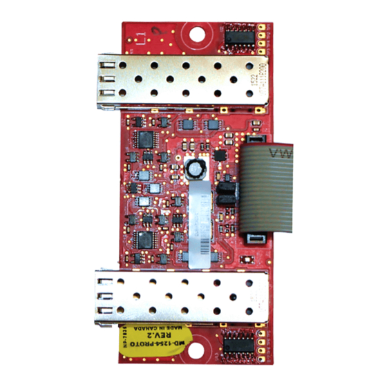
Side A Connect to P10 on the FNC-2000 Figure 1 FOM-2000-UM connections, LEDs, and jumpers Connections for Optical Modules There are 2 bays for optical modules. L1 corresponds to Side A in the FleX-Net™ or MMX™ network. L2 corresponds to Side B. -
Page 6: Installation
End cap Figure 2 Optical module lever and end cap 1. Insert the module into one of the metal bays on the FOM-2000-UM. The lever must be closed as shown in Figure 3. The module should slide in easily. Figure 3... - Page 7 3. To protect the module from dust, leave the end cap on until the fiber cable is connected to the board. Figure 5 Optical module in FOM-2000-UM with end cap To remove an optical module 1. Remove the end cap.
-
Page 8: Installation Of Fiber Optic Cables
2. Install the supplied spacers on the two bottom mounting holes of the FNC-2000 network controller. 3. Connect the FOM-2000-UM to connector P10 on the FNC-2000. 4. Install the FOM-2000-UM on the spacers with the optical module bays facing out as shown in Figure 7. 5. Remove the protective cap from the optical module. -
Page 9: Wiring
Wiring Wire from L1 to L2 A maximum of 63 nodes can be connected. Always connect L1 to L2 on the next node, and always connect TX to RX on the next node, as shown in Figure 8. Attention: Do not connect L1 to L1, or L2 to L2. If you do, the network might not function correctly. -
Page 10: Class B (Style 4)
See Figure 11. • On nodes with mixed connections, only one optical module is used. Remove the jumper corresponding to the unused bay on the FOM-2000-UM. • See LT-6014, the FNC-2000 Installation Instructions, for more information on installing and wiring the FNC-2000. -
Page 11: Mixed Fiber Types
Wiring LINE A LINE B LINE A LINE B FNC-2000 FNC-2000 JW2 open JW1 open Figure 11 Mixed copper and fiber networks Mixed Fiber Types Multi-mode and single mode can be used in a system as long as fiber pairs are of the same type. -
Page 12: Specifications
Specifications Single-Mode Single-mode 9/125 μm Fiber type: LC Duplex Connection type: Alarm: 16 mA @ 24 VDC Input rating: Standby: 16 mA @ 24 VDC 9.8 dB Optical link budget: 1310 nm Wavelength: 0 °C to 49 °C ambient, 93% relative humidity (non- Temperature range: condensing) 10 km... - Page 13 CANADA - Main Office U.S.A © Mircom 2018 25 Interchange Way 4575 Witmer Industrial Estates Printed in Canada Vaughan, ON L4K 5W3 Subject to change without prior notice Niagara Falls, NY 14305 Tel: (905) 660-4655 Tel: (905) 660-4655 www.mircom.com (888) 660-4655 (888) 660-4655 Fax: (905) 660-4113 Fax: (905) 660-4113...
Need help?
Do you have a question about the FOM-2000-UM and is the answer not in the manual?
Questions and answers