Table of Contents
Advertisement
Quick Links
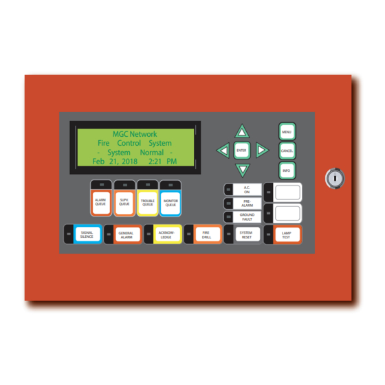
RAXN-LCD
Network Remote Annunciator Panel
Installation and Wiring Manual
MGC Network
Fire Control System
- System
Normal -
Feb 21, 2018
2:21 PM
ALARM
SUPV.
TROUBLE
MONITOR
QUEUE
QUEUE
QUEUE
QUEUE
SIGNAL
ACKNOW-
GENERAL
SILENCE
ALARM
LEDGE
MENU
ENTER
CANCEL
INFO
A.C.
ON
PRE-
ALARM
GROUND
FAULT
FIRE
SYSTEM
LAMP
DRILL
RESET
TEST
LT-895 Rev 3
Feb 2018
Advertisement
Table of Contents

Related Manuals for MGC RAXN-LCD

Summary of Contents for MGC RAXN-LCD
- Page 1 RAXN-LCD Network Remote Annunciator Panel MGC Network MENU Fire Control System - System Normal - ENTER CANCEL Feb 21, 2018 2:21 PM INFO A.C. ALARM SUPV. TROUBLE MONITOR PRE- QUEUE QUEUE QUEUE QUEUE ALARM GROUND FAULT SIGNAL ACKNOW- FIRE SYSTEM...
-
Page 3: Table Of Contents
Table of Contents Introduction Installation Instructions Jumper Settings DIP Switch Settings Wiring Instructions Cable Connections Specifications Battery Calculations Warranty and Warning Information... -
Page 5: Introduction
Introduction Introduction MGC’s remote shared display is the RAXN-LCD. The RAXN-LCD provides a replica of the main Fire Alarm Panel display at a remote location. It is equipped with a large 4 line x 20 character back-lit alphanumeric LCD display that uses a simple menu system complete with a directional keypad and switches for Enter, Menu, Cancel and Info. -
Page 6: Installation Instructions
Installation Instructions Installation Instructions The RAXN-LCD chassis is mounted with four HEX nuts. Figure below shows the RAXN-LCD mounted into a BB-1001D/R (MMX-BB-1001D/R) backbox. Dimensions for height and mounting hole locations change for the various backboxes as shown in the table below. -
Page 7: Jumper Settings
41 frames. LCD Display Printer Connection Contrast Adjust 24V POWER TERMINALS RS-485 TERMINALS Jumpers: JW2, JW1, JW3 MGC Network Fire Alarm Control System - System Normal - February 21, 2018 10:08 AM TROUBLE MONITOR ALARM SUPV. -
Page 8: Dip Switch Settings
DIP switches of SW1. The RAXN-LCD SW1 DIP switches are set by selecting the active ON. The addresses available for the RAXN-LCD are 33 to 39, inclusive. Set the address as follows in the table below: RAXN-LCD Remote Annunciator Address Setting (DIP SWITCH SW1) -
Page 9: Wiring Instructions
Wiring Instructions Wiring Instructions RS-485 Wiring The RS-485 wiring to the RAXN-LCD Display Module ALL CIRCUITS ARE POWER LIMITED RAXN-LCDG recommended AND MUST USE TYPE FPL, FPLR, OR twisted shielded pair as FPLP POWER LIMITED CABLE shown in the diagram to the right. -
Page 10: Cable Connections
Cable Connections Cable Connections The RAXN-LCD may be utilized by itself in a remote location or within a larger enclosure together with other display modules. It may also be used as part of a mass notification system. Below is an example of a RAXN-LCD and a RAX-1048TZDS 48 LED Annunciator Display module in a BB-1002D/R (MMX-BB-1002D/R) enclosure. -
Page 11: Specifications
Standby: 139 mA Max., All LEDs ON: 164 mA Max. RAX-1048TZDS Adder Annunciator Module (48 Display Points) • Interconnects via one ribbon cable from RAXN-LCD or to previous RAX-1048TZDS or IPS-2424DS to the next RAX-1048TZDS or IPS-2424DS. • Annunciation of up to 48 additional points. -
Page 12: Battery Calculations
Battery Calculations Battery Calculations Current Drain for Battery Calculations The following are the currents for the RAXN-LCD to which is added the number of RAX-1048TZDS and/or IPS-2424DS or FDX-008W/KI used: Normal Standby Current = 139 mA + ___________ x 22 mA + ___________ x 10mA = _______... -
Page 13: Warranty And Warning Information
Warranty and Warning Information Warranty and Warning Information WARNING! Please read this document CAREFULLY, as it contains important warnings, life-safety, and practical information about all products manufactured by the Mircom Group of Companies, including Mircom and Secutron branded products, which shall include without limitation all fire alarm, nurse call, building automation and access control and card access products (hereinafter individually or collectively, as applicable, referred to as “Mircom System”). - Page 14 Warranty and Warning Information The testing should include all sensing devices, keypads, consoles, alarm indicating devices and any other operational devices that are part of the system. NOTE TO USERS: All Mircom Systems have been carefully designed to be as effective as possible. However, there are circumstances where they may not provide protection.
- Page 15 Warranty and Warning Information 13. Wireless Devices Placement Proximity. Moreover all wireless devices must be a minimum and maximum distance away from large metal objects, such as refrigerators. You are required to consult the specific Mircom System manual and application guide for any maximum distances required between devices and suggested placement of wireless devices for optimal functioning.
- Page 16 CANADA - Main O ce U.S.A © MGC 2018 25 Interchange Way 4575 Witmer Industrial Estates Printed in Canada Vaughan, ON L4K 5W3 Niagara Falls, NY 14305 Subject to change without prior notice Tel: (888) 660-4655 Tel: (888) 660-4655 (905) 660-4655 (905) 660-4655 www.mircom.com...
Need help?
Do you have a question about the RAXN-LCD and is the answer not in the manual?
Questions and answers