Table of Contents
Advertisement
Available languages
Available languages
Quick Links
ME 200
[de]
ME 200
[cs]
ME 200
[en]
ME 200
[fr]
ME 200
[fl]
ME 200
[it]
ME 200
[pl]
ME 200
nstallationsanleitung für den Fachmann . . . . . . . . . . . . . . . . . . . . . . . . . . . . . . . . . . . . 2
Návod k instalaci pro odbornou firmu . . . . . . . . . . . . . . . . . . . . . . . . . . . . . . . . . . . . . 13
Installation instructions for contractors. . . . . . . . . . . . . . . . . . . . . . . . . . . . . . . . . . . . 24
Notice d'installation pour le professionnel . . . . . . . . . . . . . . . . . . . . . . . . . . . . . . . . . 35
Installatiehandleiding voor de installateur. . . . . . . . . . . . . . . . . . . . . . . . . . . . . . . . . . 48
Istruzioni per l'installazione per tecnico specializzato . . . . . . . . . . . . . . . . . . . . . . . . 59
Instrukcja montażu dla instalatora . . . . . . . . . . . . . . . . . . . . . . . . . . . . . . . . . . . . . . . . 72
0010016167-001
Advertisement
Chapters
Table of Contents

Related Manuals for Bosch ME 200


Summary of Contents for Bosch ME 200
- Page 1 ME 200 [de] ME 200 nstallationsanleitung für den Fachmann ........2 [cs] ME 200 Návod k instalaci pro odbornou firmu .
-
Page 2: Table Of Contents
Inhaltsverzeichnis Inhaltsverzeichnis Symbolerklärung und Sicherheitshinweise Symbolerklärung Symbolerklärung und Sicherheitshinweise ....2 Symbolerklärung ....... 2 Warnhinweise Allgemeine Sicherheitshinweise . -
Page 3: Angaben Zum Produkt
Betriebsbedingungen der Heizungs- – MX25 ab V1.44 anlage ein. • Das Modul ME 200 bietet die Möglichkeit zur Sperre des konventio- ▶ Bedienung erklären – dabei besonders auf alle si- nellen Wärmeerzeugers bei ausreichender Wärme des Pufferspei- chers. -
Page 4: Wichtige Hinweise Zur Verwendung
Heizkreispumpe Heizkreis 1: In einem System mit autarkem alternati- • Anzeigebereich • – 30 ... 50 °C ven Wärmeerzeuger (ME 200 Adresse 10) kann das Modul die Heizkreis- • obere Fehlergrenze • > 125 °C pumpe des ersten Heizkreises je nach Wärmebedarf ein- /ausschalten. -
Page 5: Ergänzendes Zubehör
▶ Vor Installation dieses Produktes: Wärmeerzeuger und alle weiteren • 300 m mit 1,50 mm Leiterquerschnitt BUS-Teilnehmer allpolig von der Netzspannung trennen. BUS-Verbindung ME 200 – Bedieneinheit – andere Module ▶ Vor Inbetriebnahme: Abdeckung anbringen ( Bild 18 am Dokumentende). ▶ Bei unterschiedlichen Leiterquerschnitten Verteilerdose für den An- schluss der BUS-Teilnehmer verwenden. -
Page 6: Anschluss Spannungsversorgung, Pumpe Und Mischer (Netzspannungsseite 230V)
Installation Bezeichnungen der Anschlussklemmen (Kleinspannungsseite ≤ 24 V) Anschluss Steuersignal zum Sperren des konventionellen Die maximale Leistungsaufnahme der angeschlossenen Bauteile und Wärmeerzeugers (Anschlussklemme EV / I3 am konventionellen Baugruppen darf die in den technischen Daten des Moduls angegebene Wärmeerzeuger) ( Konfiguration in Tabelle 11: Öffner/ Leistungsabgabe nicht überschreiten. -
Page 7: Überblick Anschlussklemmenbelegung
Anlagenteile angeschlossen werden können. Je nach Anlage kann eines Verwendung des Moduls ist der gleichzeitige Anschluss einiger Bauteile der Bauteile an der Anschlussklemme angeschlossen werden erforderlich oder ausgeschlossen. PWM: 1-2 ME 200 0-10 V: 1-3 4 5 6 1 2 3 24 V... -
Page 8: Kodierschalter Einstellen
(z. B. Scheitholz- oder Kaminofen). zum ME 200 anhand der angeschlossenen Fühler. Konfig. Relaisausgang Aus: Kein Anschluss an VR2 10.Die Einstellungen im Menü ME 200 prüfen ( Tabelle 7 bis 11) und (VR2) Bypass: Bypassventil für konventionellen ggf. auf die installierte Anlage abstimmen. - Page 9 Inbetriebnahme Menüpunkt Einstellbereich: Funktionsbeschreibung Menüpunkt Einstellbereich: Funktionsbeschreibung Minleistung Pumpe 12 ... 35 ... 50 %: Die minimal erlaubte Leistung der Warmwasser über Ja: Pufferspeicher wird für Warmwasserbereitung Pufferladepumpe im Regelbetrieb. Der Einstellwert Puffer genutzt. bezieht sich auf Prozent der maximalen Nein: Keine Warmwasserbereitung über Pumpenleistung.
-
Page 10: Menü Diagnose
▶ Modul aus- und wieder war kurz falsch einschalten. Funktionstest angeschlossen. Wenn ein Modul ME 200 installiert ist, wird das Menü Funktionstest > Kodierschalter auf ▶ Kodierschalter einstellen. Typ AWE angezeigt. ungültiger Position In diesem Menü kann die Funktion der am Modul angeschlossenen Gerä- oder in te getestet werden. -
Page 11: Betriebsanzeige "1": Alternativer Wärmeerzeuger
Störungen beheben Betriebsanzeige “1”: Alternativer Wärmeerzeuger Betriebsanzeige “3”: Pufferspeicher Zustandsanzeige Mögliche Ursache Abhilfe Zustandsanzeige Mögliche Ursache Abhilfe dauernd aus keine Normalbetrieb dauernd aus Temperaturfühler ▶ Anschluss der Temperaturfühler Wärmeanforderung nicht verfügbar prüfen. dauernd rot Temperaturfühler ▶ Modul aus- und wieder ▶... -
Page 12: Übersicht Des Servicemenüs
Übersicht des Servicemenüs Umweltschutz/Entsorgung Die Menüs sind von der installierten Bedieneinheit und der installierten Umweltschutz ist ein Unternehmensgrundsatz der Bosch Gruppe. Anlage abhängig. Die Menüpunkte erscheinen entsprechend der unten Qualität der Produkte, Wirtschaftlichkeit und Umweltschutz sind für uns aufgelisteten Reihenfolge. -
Page 13: Vysvětlení Symbolů A Bezpečnostní Pokyny
Obsah Obsah Vysvětlení symbolů a bezpečnostní pokyny Použité symboly Vysvětlení symbolů a bezpečnostní pokyny....13 Použité symboly .......13 Výstražné... -
Page 14: Údaje O Výrobku
MM 100 (adresa 9 nebo 10). H Nebezpečí poškození mrazem • K nabíjení akumulační nádrže přes ME 200 musí být alternativní zdroj tepla teplovodní a musí umožňovat čidlo teploty na výstupu. Pokud se Je-li zařízení mimo provoz, hrozí jeho zamrznutí: čidlo teploty na výstupu při stojícím čerpadle nezahřeje, je... -
Page 15: Důležité Poznámky K Používání
3 čidla teploty (12 k, 9 mm), použitelná jako čidla teploty na Postupujte podle návodu ke zdroji tepla. výstupu, vratném potrubí nebo čidla teploty zásobníku • Pokud alternativní zdroj tepla nabíjí zásobník teplé vody a ME 200 aktivně ovládá alternativní zdroj tepla, měla by být požadovaná Technické údaje teplota při nabíjení... -
Page 16: Doplňkové Příslušenství
Dotyk s díly pod elektrickým napětím může vést k úrazu elektrickým • 300 m s průřezem vodiče 1,50 mm proudem. Sběrnicové spojení ME 200 – samostatná řídicí jednotka – ostatní ▶ Před instalací tohoto výrobku: Proveďte kompletní odpojení všech moduly pólů... -
Page 17: Připojení Napájení Čerpadla A Směšovače (Strana Síťového Napájení 230 V) Elektrickým Proudem
Instalace Označení připojovacích svorek (strana malého napětí ≤ 24 V) Připojení čerpadla alternativních zdrojů tepla s pulzně šířkovou Maximální příkon připojených dílů a sestav nesmí překročit odevzdaný modulací nebo signálem 0-10 V (Output Return) výkon, který je uveden v technických údajích modulu. Připojení... -
Page 18: Přehled Osazení Připojovacích Svorek
Vždy v závislosti na systému lze jeden z potřebné nebo vyloučeno současné připojení několika dílů. dílů připojit na připojovací svorku (např. „VR2“ nebo „PR2“ na PWM: 1-2 ME 200 0-10 V: 1-3 4 5 6 1 2 3... -
Page 19: Uvedení Do Provozu
▶ Nastavte teplotu zvýšení teploty vratné vody alternativního zdroje Konfigurační asistent sestaví návrh konfigurace k ME 200 na základě tepla podle údajů výrobce. připojených čidel. 10.Zkontrolujte nastavení v nabídce ME 200 ( tabulka 24 až 28) a příp. slaďte na instalovaný systém. Položka nabídky Rozsah nastavení: Popis funkce Ovládání... - Page 20 Uvedení do provozu Nabíjecí čerp. akumulace Akumulace Položka nabídky Rozsah nastavení: Popis funkce Položka nabídky Rozsah nastavení: Popis funkce Konfig. čerpadla Ano: Nabíjecí čerpadlo akumulace připojeno na modulu Pož. tepl. na výstupu 40* ... 70 ... 75 °C: Požadovaná teplota pro nabíjení (PR1).
-
Page 21: Menu Diagnostika
Test funkcí Autom. Konvenční zdroj tepla se uvolní v případě, že Je-li nainstalován modul ME 200, zobrazí se nabídka Test funkcí akumulační nádrž nemůže být nabíjena alternativním > Typ AZT. zdrojem tepla. Jinak zůstane konvenční zdroj tepla V této nabídce lze otestovat funkci zařízení... -
Page 22: Zobrazení Provozního Stavu "1": Alternativní Zdroj Tepla
Odstraňování poruch Zobrazení provozního stavu "3": akumulační nádrž Zobrazení Možná příčina Odstranění provozního stavu Stavový Možná příčina Odstranění Trvale červená Čidlo teploty bylo ▶ Modul vypněte a opět zapněte. indikátor krátce chybně Trvale vypnuto Čidlo teploty není k ▶ Zkontrolujte připojení čidel připojeno. -
Page 23: Přehled Servisního Menu
Přehled servisního menu Ochrana životního prostředí a likvidace odpadu Nabídky závisejí na instalované samostatné řídicí jednotce a Ochrana životního prostředí je podniková zásada skupiny Bosch. instalovaném systému. Položky menu se objevují v níže uvedeném Kvalita výrobků, hospodárnost provozu a ochrana životního prostředí... -
Page 24: Explanation Of Symbols And Safety Instructions
Table of contents Table of contents Explanation of symbols and safety instructions Explanation of symbols Explanation of symbols and safety instructions ..24 Explanation of symbols ......24 Warnings General safety instructions . -
Page 25: Product Information
H Damage caused by frost function. • To charge the buffer cylinder via the ME 200, the alternative heat The solar system can freeze if it is switched off: source must be water routing and must allow installation of a flow ▶... -
Page 26: Important Notices On Use
Coding Function of module cannot be connected to the terminal OEV of the ME 200. Off (as-delivered condition) or Reset module settings • In addition to the alternative heat source, only use gas or oil-fired heat System with alternative heat source and conventional heat sources in a system. -
Page 27: Additional Accessories
▶ Before commissioning: mount cover ( Fig. 18 at end of document). • 300 m with 1.50 mm conductor cross-section BUS connection between ME 200 – control unit – other modules Installation ▶ If the conductor cross-sections vary, use a junction box to connect ▶... -
Page 28: Connecting The Power Supply, Pump And Mixer (Mains Voltage Side 230 V)
Installation Terminal designations (extra-low voltage side ≤ 24 V) Connection of pump of alternative heat source with pulse width The maximum power consumption of the connected components and modulation or 0-10 V signal (Output Return) assemblies must not exceed the power output stated in the Connection of control signal for blocking of conventional heat specifications for the module. -
Page 29: Overview Of The Terminal Assignment
(e.g. “VR2” or “PR2” or may need to be excluded. PWM: 1-2 ME 200 0-10 V: 1-3 4 5 6 1 2 3... -
Page 30: Setting The Coding Switch
(VR2) Bypass: bypass valve connected for conventional heat 10.Check the settings in the ME 200 menu ( Tab. 41 to 45) and adjust source. to the installed system if required. HC1 PM: pump for heating circuit 1 connected to VR2, can only be used for stand-alone alternative heat source (coding switch setting 10). - Page 31 Commissioning Menu item Setting area: function description Menu item Setting area: function description Start conf. pump Temp.: the pump at the alternative heat source is Config. DHW cylinder Notice: a default setting does not exist. During started if temperature sensor TA1/TF1 detects heat in commissioning, either "Dual: DWH…"...
-
Page 32: Diagnosis Menu
Function test Faulty fuse ▶ When the power supply is If a ME 200 module is installed, the menu Function test > AHS type is switched off, replace the fuse displayed. ( Fig. 17 at end of this document). -
Page 33: Status Indicator "2": Heat Source Bypass Valve/Pump For Heating Circuit 1 (Stand-Alone)
Overview of the service menu Status indicator "2": heat source bypass valve/pump Overview of the service menu for heating circuit 1 (stand-alone) The menus depend on which control unit and system is installed. The Status indicator Description menu items are displayed in the sequence listed below. Constantly OFF Stand-alone alternative heat source: Service menu... -
Page 34: Environmental Protection/Disposal
Environmental protection/disposal Environmental protection/disposal Environmental protection is a key commitment of the Bosch Group. Quality of products, efficiency and environmental protection are equally important objectives for us. Environmental protection laws and regulations are strictly observed. To protect the environment, we use the best possible technology and materials while taking into account economic considerations. -
Page 35: Explication Des Symboles Et Mesures De Sécurité
Sommaire Sommaire Explication des symboles et mesures de sécurité Explications des symboles Explication des symboles et mesures de sécurité ..35 Explications des symboles..... . .35 Avertissements Consignes générales de sécurité... -
Page 36: Informations Sur Le Produit
ECS. d’utilisation en le priant de les conserver à proximité • Pour le chargement du ballon tampon par le ME 200, le générateur de de l’installation de production d'eau chaude sanitaire. chaleur alternatif doit avoir une circulation d’eau et permettre une sonde de température de départ. -
Page 37: Consignes D'utilisation Importantes Relatives À L'utilisation
Pompe du circuit de chauffage 1 : dans un système avec générateur de peut remplacer la vanne de mélange. chaleur alternatif autonome (ME 200 adresse 10), le module peut acti- • Si le générateur de chaleur alternatif ne produit que l’eau chaude ver/désactiver la pompe du premier circuit de chauffage en fonction du... -
Page 38: Accessoires Complémentaires
Installation Caractéristiques techniques Installation Puissance de sortie maxi. par raccordement DANGER : • PR1 • 400 W (pompes haute Danger de mort par électrocution ! efficience autorisées ; Tout contact avec des pièces électrique, qui sont sous tension, peut pro- <30 A pour 10 ms) voquer une électrocution. -
Page 39: Raccordement Électrique
Raccordement vanne de mélange (Valve Return/ Buffer) | Vanne d’inversion Connexion BUS ME 200 - module de commande - autres modules Raccordement de la vanne d’inversion pour le by-pass ▶ Si les sections des conducteurs ne sont pas les mêmes, utiliser le boî- du générateur de chaleur traditionnel ou pour la pompe... -
Page 40: Schémas De Connexion Avec Exemples D'installation
Installation 3.3.3 Schémas de connexion avec exemples d’installation Les représentations hydrauliques ne sont que des schémas donnés à titre indicatif pour une commutation hydraulique éventuelle. Les sys- tèmes de sécurité doivent être installés selon les prescriptions locales et les normes en vigueur. Vous trouverez des informations et possibilités complémentaires dans les documents techniques de conception ou l’appel d’offre. -
Page 41: Vue D'ensemble Affectation Des Bornes De Raccordement
éléments est tion, l’un des éléments peut être raccordé à la borne de raccordement nécessaire ou exclu. PWM: 1-2 ME 200 0-10 V: 1-3 4 5 6 1 2 3 24 V... -
Page 42: Réglage De L'interrupteur Codé
à l’aide des sondes raccordées. altern. active le générateur de chaleur alternatif selon les 10.Vérifier les réglages dans le menu ME 200 ( tabl. 58 à 62) et les besoins (contacteur mécanique nécessaire sur le adapter à l’installation en place le cas échéant. - Page 43 Mise en service Pompe charge bal. tamp. Tampon Option Plage de réglage : description des fonctions Option Plage de réglage : description des fonctions Configuration pompe Oui: pompe de charge du ballon tampon raccordée au Temp. cons. départ 40* ... 70 ... 75 °C : température de consigne pour le module (PR1).
-
Page 44: Menu Diagnostic
Tests fonc. Auto.: le générateur de chaleur traditionnel est autorisé Si un module ME 200 est installé, le menu Tests fonc. > Type génér. lorsque le ballon tampon ne peut pas être réchauffé par chal. altern. s’affiche. le générateur de chaleur alternatif. Dans le cas Ce menu permet de tester le fonctionnement des appareils raccordés au... -
Page 45: Témoin De Fonctionnement Du Module (Intégré Sur L'interrupteur Codé)
Eliminer les défauts Témoin de fonctionnement du module Témoin de fonctionnement « 1 » : générateur de cha- (intégré sur l’interrupteur codé) leur alternatif Témoin de Cause possible Solution Affichage d’état Cause possible Solution fonctionnement Continuellement Pas de demande de Mode normal Continuellement Alimentation... -
Page 46: Témoin De Fonctionnement " 3 " : Ballon Tampon
Aperçu des menus de service Témoin de fonctionnement « 3 » : ballon tampon Aperçu des menus de service Affichage d’état Cause possible Solution Les menus dépendent du module de commande et de l’installation en Continuellement Sonde de ▶ Contrôler le raccordement de la place. -
Page 47: Protection De L'environnement/Recyclage
Protection de l’environnement/Recyclage Protection de l’environnement/Recyclage La protection de l’environnement est une valeur de base du groupe Bosch. Nous accordons une importance égale à la qualité de nos produits, à leur rentabilité et à la protection de l’environnement. Les lois et prescriptions concernant la protection de l’environnement sont strictement observées. -
Page 48: Toelichting Bij De Symbolen En Veiligheidsinstructies
Inhoudsopgave Inhoudsopgave Toelichting bij de symbolen en veiligheidsin- structies Toelichting bij de symbolen en veiligheidsinstructies ..48 Symboolverklaringen Symboolverklaringen ......48 Algemene veiligheidsvoorschriften. -
Page 49: Gegevens Betreffende Het Product
MM 100 (adres 9 of 10) voor de regeling van de warmwaterfunctie nodig. ▶ Geef de installatie- en bedieningshandleidingen • Voor het beladen van het buffervat door de ME 200 moet de alterna- aan de eigenaar in bewaring. tieve warmteproducent waterdoorstroomd zijn en een aanvoertem- H Schade door vorst peratuursensor mogelijk maken. -
Page 50: Belangrijke Adviezen Voor Het Gebruik
CV-pomp cv-circuit 1: in een systeem met autonome alternatieve warm- • Onderste foutgrens • < – 10 °C teproducent (ME 200 adres 10) kan de module de cv-pomp van het eer- • Weergavebereik • 0 ... 100 °C ste cv-circuit afhankelijk van de warmtevraag in-/uitschakelen. -
Page 51: Aanvullend Toebehoren
• 300 m met 1,50 mm geleiderdiameter deelnemers over alle polen losmaken van de netspanning. BUS-verbinding ME 200 – bedieningseenheid – andere module ▶ Voor de inbedrijfstelling: breng de afdekking aan ( afb. 18 aan het ▶ Gebruik bij verschillende geleiderdiameters een verdeeldoos voor de einde van het document). -
Page 52: Aansluiting Voedingsspanning Pomp En Mengkraan (Netspanningszijde 230 V)
Installatie Algemeen over laagspanningszijde ▶ Gebruik alleen elektriciteitskabels van dezelfde kwaliteit. ▶ Let erop dat de fasen van de netaansluiting correct worden Benamingen van de aansluitklemmen (laagspanningszijde ≤ 24 V) geïnstalleerd. 1)2) Aansluiting op regelaar, module, warmteproducent, wanneer Netaansluiting via een stekker met randaarde is niet toegestaan. conventionele warmteproducent in systeem met alternatieve ▶... -
Page 53: Overzicht Bezetting Aansluitklemmen
één van de bouwdelen op de aansluitklem worden aangesloten bouwdelen nodig of uitgesloten. PWM: 1-2 ME 200 0-10 V: 1-3 4 5 6 1 2 3 24 V... -
Page 54: Codeerschakelaar Instellen
ME 200 aan de hand van de aangesloten sensor. Nee: passieve alternatieve warmteproducent. Geen 10.Controleer de instellingen in het menu ME 200 ( tabel 75 tot 79) actieve aansturing van de alternatieve en eventueel op de geïnstalleerde installatie afstemmen. - Page 55 Inbedrijfstelling Menupunt Instelbereik: functiebeschrijving Menupunt Instelbereik: functiebeschrijving Min. vermogen pomp 12 ... 35 ... 50 %: het minimaal toegestane vermogen Mengerlooptijd 0 ... 120 ... 600 s: maximale looptijd van mengkraan/ van de bufferlaadpomp in regelbedrijf. De instelwaarde bypass ventiel voor bypass van het buffervat. is gerelateerd aan de procentuele waarde van het Warmwater via buffer Ja: buffervat wordt voor warmwaterbereiding gebruikt.
-
Page 56: Menu Diagnose
▶ Schakel de module uit en weer in. was kort verkeerd Functietest aangesloten. Wanneer een module ME 200 is geïnstalleerd, wordt het menu Functie- Codeerschakelaar op ▶ Stel de codeerschakelaar in. test > Type AWP getoond. ongeldige positie of in In dit menu kan de werking van de op de module aangesloten toestellen tussenstand. -
Page 57: Bedrijfsindicatie "1": Alternatieve Warmteproducent
Storingen verhelpen Bedrijfsindicatie "1": alternatieve warmteproducent Toestandsindicatie MOGELIJKE Oplossing OORZAAK Toestandsindicatie MOGELIJKE Oplossing Constant rood Temperatuursensor ▶ Schakel de module uit en weer in. OORZAAK was kort verkeerd Constant uit Geen warmtevraag Normaal bedrijf aangesloten. Constant rood Temperatuursensor ▶ Schakel de module uit en weer in. Temperatuursensor ▶... -
Page 58: Overzicht Van De Servicemenu's
Overzicht van de servicemenu's Milieubescherming/afvalverwerking De menu's zijn afhankelijk van de geïnstalleerde bedieningseenheid en Milieubescherming is een ondernemingsprincipe van de Bosch groep. de geïnstalleerde installatie. De menupunten verschijnen overeenkom- Kwaliteit van de producten, rendement en milieubescherming zijn even stig de hieronder getoonde volgorde. -
Page 59: Significato Dei Simboli E Avvertenze Di Sicurezza
Indice Indice Significato dei simboli e avvertenze di sicurezza Significato dei simboli Significato dei simboli e avvertenze di sicurezza ..59 Significato dei simboli ......59 Avvertenze di sicurezza generali Avvertenze di sicurezza generali . -
Page 60: Descrizione Del Prodotto
BUS EMS 2 è supportato con i seguenti termoregolatori: istruire il gestore in merito all'utilizzo e alle condizioni di – MX25 da V1.44 • Il modulo ME 200 offre la possibilità di disattivare il generatore di funzionamento dell'impianto di riscaldamento. calore convenzionale in caso di calore sufficiente dell'accumulatore ▶... -
Page 61: Indicazioni Importanti Sull'utilizzo
Circolatore circuito di riscaldamento 1: in un sistema con generatore Indicazioni importanti sull'utilizzo di calore autonomo (ME 200 indirizzo 10) il modulo può accendere/spe- Il modulo comunica mediante un'interfaccia EMS 2 con altre utenze BUS gnere il circolatore del primo circuito di riscaldamento a seconda del fab- che dispongono di interfaccia EMS 2. -
Page 62: Accessori Complementari
Installazione Dati tecnici Installazione Potenza max. in uscita per ogni collegamento PERICOLO: • PR1 • 400 W (sono consentite pompe Pericolo di morte per corrente elettrica! di circolazione modulanti ad Toccando componenti elettrici sotto tensione si rischia la folgorazione. alta efficienza; < 30 A per 10 ms) ▶... -
Page 63: Collegamento Elettrico
(Pump Return) • 300 m con sezione del conduttore 1,50 mm Collegamento segnale di comando generatore di calore Collegamento BUS ME 200 – Termoregolatore – altri moduli alternativo con segnale ON/OFF con tensione di alimentazione elettrica di rete (Output Alternative) ▶... -
Page 64: Schemi Elettrici Di Collegamento Con Esempi Di
Installazione 3.3.3 Schemi elettrici di collegamento con esempi di impianti Le rappresentazioni idrauliche sono solo schematiche e danno un esem- pio non vincolante di un possibile sistema idraulico. I dispositivi di sicu- rezza devono essere realizzati secondo le normative valide e i regolamenti locali. -
Page 65: Panoramica Sull'occupazione Dei Morsetti Di Collegamento
«VR2»). A seconda dell'utilizzo del modulo è necessario o escluso A seconda dell'impianto può essere collegato uno dei componenti al il contemporaneo collegamento di alcuni componenti. PWM: 1-2 ME 200 0-10 V: 1-3 4 5 6 1 2 3... -
Page 66: Impostazione Del Selettore Di Codifica
Voce di menu Campo d'impostazione: Descrizione del funzionamento 10.Controllare le impostazioni nel menu ME 200 ( tabella da 92 a 96) ed event. adattarle all'impianto installato. Azionam. AWE SÌ: generatore di calore alternativo attivo. Il modulo accende il generatore di calore alternativo a seconda del fabbisogno (necessario avere un contatto di commutazione sul generatore di calore alternativo). - Page 67 Messa in funzione Pompa carico acc. inerz. Accumulatore inerziale Voce di menu Campo d'impostazione: Descrizione del Voce di menu Campo d'impostazione: Descrizione del funzionamento funzionamento Config. pompa SÌ: pompa di carico inerziale collegata sul modulo T.nom.mand.GCA. 40* ... 70 ... 75 °C: Temperatura nominale per il (PR1).
-
Page 68: Menu Diagnosi
Test funzionale del riscaldamento. Se è installato un modulo ME 200 viene visualizzato il menu Test funzio- Autom.: il generatore di calore convenzionale viene nale > Tipo AWE. abilitato se l'accumulatore inerziale non può essere In questo menu può... -
Page 69: Indicatore Di Funzionamento Del Modulo (Integrato Nel Selettore Di Codifica)
Eliminazione delle disfunzioni Indicatore di funzionamento del modulo Indicatore di funzionamento "1": generatore di (integrato nel selettore di codifica) calore alternativo Indicatore di Possibile causa Rimedio Indicatore di Possibile causa Rimedio funzionamento stato Costantemente Tensione di ▶ Inserire la tensione di Costantemente nessuna richiesta Funzionamento normale... -
Page 70: Indicatore Di Funzionamento "3": Accumulatore
Panoramica del menu di servizio (manutenzione) Indicatore di funzionamento "3": accumulatore Panoramica del menu di servizio (manutenzione) inerziale I menu dipendono dal tipo di termoregolatore installato e dall'impianto Indicatore di stato Possibile causa Rimedio installato. Le voci di menu vengono visualizzate secondo la sequenza Costantemente Sonda di temperatura ▶... -
Page 71: Protezione Dell'ambiente/Smaltimento
Protezione dell'ambiente/smaltimento Protezione dell'ambiente/smaltimento La protezione dell'ambiente è un principio fondamentale per il gruppo Bosch. La qualità dei prodotti, il risparmio e la tutela dell'ambiente sono per noi obiettivi di pari importanza. Ci atteniamo scrupolosamente alle leggi e alle norme per la protezione dell'ambiente. -
Page 72: Objaśnienie Symboli I Wskazówki Dotyczące Bezpieczeństwa
Spis treści Spis treści Objaśnienie symboli i wskazówki dotyczące bezpieczeństwa Objaśnienie symboli i wskazówki dotyczące bezpieczeństwa ........72 Objaśnienie symboli Objaśnienie symboli. -
Page 73: Ogólne Zalecenia Bezpieczeństwa
Objaśnienie symboli i wskazówki dotyczące bezpieczeństwa H Odbiór przez użytkownika Ogólne zalecenia bezpieczeństwa W trakcie odbioru należy udzielić użytkownikowi H Wskazówki dla grupy docelowej informacji na temat obsługi i warunków eksploatacji Niniejsza instrukcja montażu adresowana jest do instalacji ogrzewczej. monterów instalacji gazowych i wodnych oraz ▶... -
Page 74: Informacje O Produkcie
MM 100 (adres 9 lub 10) do regulacji funkcji c.w.u. Regulacja aktywnych, alternatywnych urządzeń grzewczych: Moduł może bezpośrednio włączać/wyłączać lub, jeśli to możliwe, modulować • Do ładowania zasobnika buforowego przez ME 200 alternatywne urządzenie grzewcze musi przewodzić wodę i umożliwiać elektrycznie sterowane, alternatywne urządzenia grzewcze (np. kotły na pelet z przepływem wody). -
Page 75: Ustawianie Przełącznika Kodującego
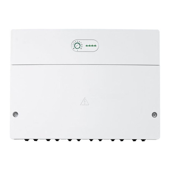
IP 44 Klasa ochronności Zakres dostawy Nr ident. Tabliczka znamionowa ( rys. 19 Rys. 1 na końcu dokumentu: na końcu dokumentu) Moduł ME 200 Temperatura kontroli ciśnienia 75 °C Torebka z dławikami odciążającymi w zaworze kulowym Instrukcja montażu Stopień zabrudzenia 3 czujniki temperatury (12 k, 9 mm), do zastosowania jako... -
Page 76: Instalacja
• 300 m przy przekroju przewodu 1,50 mm Instalacja ▶ Zainstalować moduł na ścianie ( rys. 3 do rys. 5 na końcu Połączenie magistrali BUS ME 200 – moduł obsługowy – inne dokumentu), na szynie montażowej ( rys., str. 6) lub moduły w odpowiednim podzespole. -
Page 77: Przyłącze Napięcia Zasilającego, Pompy I Zaworu Mieszającego (Strona Napięcia Sieciowego 230 V)
Instalacja ▶ Aby uniknąć zakłóceń indukcyjnych: wszystkie kable 3.3.3 Schematy połączeń z przykładami instalacji niskonapięciowe kłaść z dala od kabli doprowadzających napięcie Prezentacje instalacji hydraulicznych są jedynie schematyczne sieciowe (minimalna odległość 100 mm). i przedstawiają niewiążące wskazówki dot. możliwości układu połączeń ▶... -
Page 78: Schemat Przyporządkowania Zacisków Przyłączeniowych
„VR2“). W zależności od zastosowania modułu jednoczesne podłączenie W zależności od instalacji jedna z części zostaje podłączona do zacisku niektórych podzespołów jest wymagane lub wykluczone. PWM: 1-2 ME 200 0-10 V: 1-3 4 5 6 1 2 3 24 V... -
Page 79: Ustawianie Przełącznika Kodującego
Wysterowanie AŹC Tak: aktywne alternatywne urządzenie grzewcze. Moduł 10.Sprawdzić ustawienia w menu ME 200 ( tabela 109 do 113) włącza alternatywne urządzenie grzewcze w zależności i w razie potrzeby dostosować je do zamontowanej instalacji. od zapotrzebowania (wymagany styk przełączający w alternatywnym urządzeniu grzewczym). - Page 80 Uruchomienie Pompa ładująca bufor Bufor Punkt menu Zakres ustawień: opis funkcji Punkt menu Zakres ustawień: opis funkcji Konfig. pompy Tak: pompa ładująca bufor podłączona do modułu (PR1). Temp. zad.zas. alt. 40* ... 70 ... 75 °C: temperatura zadana ładowania urz.grz. zasobnika buforowego moduluje do ustawionej tutaj Nie: brak pompy ładującej bufor w module.
-
Page 81: Menu Diagnoza
Test działania grzewczych: uszkodzony ▶ Sprawdzić napięcie na zaciskach Jeżeli zainstalowany jest moduł ME 200, wyświetla się menu Test czujnik temperatury przyłączeniowych czujnika działania > Typ AŹC. zewnętrznej temperatury w module. -
Page 82: Wskaźnik Stanu Pracy "1": Alternatywne Urządzenie Grzewcze
Usuwanie usterek Wskaźnik stanu pracy "1": Alternatywne urządzenie Wskaźnik stanu pracy "3": zasobnik buforowy grzewcze Wskaźnik stanu Możliwa przyczyna Środek zaradczy Wskaźnik stanu Możliwa przyczyna Środek zaradczy stale wyłączony Czujnik temperatury ▶ Sprawdzić przyłącze czujnika niedostępny temperatury. stale wyłączony Brak żądania ciepła Normalny tryb pracy ▶... -
Page 83: Przegląd Menu Serwisowego
Menu zależne są od zainstalowanego modułu obsługowego Ochrona środowiska to jedna z podstawowych zasad działalności grupy i zainstalowanej instalacji. Punkty menu wyświetlane są w podanej Bosch. poniżej kolejności. Jakość produktów, ekonomiczność i ochrona środowiska stanowią dla nas cele równorzędne. Ściśle przestrzegane są ustawy i przepisy Menu serwisowe dotyczące ochrony środowiska. - Page 84 Ochrona środowiska/utylizacja 6 mm 6 mm 3,5 mm 0010014373-001 0010014199-001 ... mm 6 mm 6 mm 3,5 mm 0010014372-001 0 010 013 238-001 0010014374-001 ME 200 – 6720884576 (2019/08)
- Page 85 Ochrona środowiska/utylizacja 6. 6. 7. 7. 5. 5. 0010014368-001 0010014371-001 6. 6. 7. 7. 5. 5. 0010014370-001 0010014367-001 0010014369-001 0010014366-001 ME 200 – 6720884576 (2019/08)
- Page 86 Ochrona środowiska/utylizacja 5. 5. 6. 6. 100 mm 100 mm 4. 4. 0010014365-001 0010014364-001 0010014363-001 0010014362-001 ME 200 – 6720884576 (2019/08)
- Page 87 Ochrona środowiska/utylizacja 0010014361-001 0 010 013 251-001 B...-6 0010028192-001 ME 200 – 6720884576 (2019/08)
- Page 88 Ochrona środowiska/utylizacja ME 200 MM100 MM100 OEV (I)MX25 ≥ V1.44 V2 – 4 OA1- DHWC ME 200 4 5 6 1 2 3 ≤ 24 V 120/230 V AC 0-10V TR1 TB1 TB2 TB3 N 14 43 44 N 14...
- Page 89 Ochrona środowiska/utylizacja MM100 ME 200 MM100 MM100 V2 – 4 OA1- DHWC ME 200 4 5 6 1 2 3 ≤ 24 V 120/230 V AC 0-10V TR1 TB1 TB2 TB3 N 14 43 44 N 14 1 2 1 2 1 2 1 ≤...
- Page 90 Ochrona środowiska/utylizacja ME 200 MM100 OEV (I)MX25 ≥ V.144 OA1- ME 200 4 5 6 1 2 3 ≤ 24 V 120/230 V AC 0-10V TR1 TB1 TB2 TB3 N 14 43 44 N 14 1 2 1 2 1 2 1 ≤...
- Page 91 Ochrona środowiska/utylizacja MM100 ME 200 AHSP ME 200 4 5 6 1 2 3 ≤ 24 V 120/230 V AC 0-10V TR1 TB1 TB2 TB3 N 14 43 44 N 14 1 2 1 2 1 2 1 ≤ 24 V...
- Page 92 Ochrona środowiska/utylizacja ME 200 MM100 MM100 OA1- ME 200 4 5 6 1 2 3 ≤ 24 V 120/230 V AC 0-10V TR1 TB1 TB2 TB3 N 14 43 44 N 14 1 2 1 2 1 2 1 ≤ 24 V...
- Page 93 Ochrona środowiska/utylizacja MM100 ME 200 MM100 MM100 V2 – 4 OA1- DHWC ME 200 4 5 6 1 2 3 ≤ 24 V 120/230 V AC 0-10V TR1 TB1 TB2 TB3 N 14 43 44 N 14 1 2 1 2 1 2 1 ≤...
- Page 94 Ochrona środowiska/utylizacja MM100 CONM ME 200 OA1- DHWC ME 200 4 5 6 1 2 3 ≤ 24 V 120/230 V AC 0-10V TR1 TB1 TB2 TB3 N 14 43 44 N 14 1 2 1 2 1 2 1 ≤...
- Page 95 Ochrona środowiska/utylizacja ME 200 OA1- ME 200 4 5 6 1 2 3 ≤ 24 V 120/230 V AC 0-10V TR1 TB1 TB2 TB3 N 14 43 44 N 14 1 2 1 2 1 2 1 ≤ 24 V...
- Page 96 Ochrona środowiska/utylizacja CONM ME 200 MM100 MM100 DHWC ME 200 4 5 6 ≤ 24 V 120/230 V AC TR1 TB1 TB2 TB3 N 14 43 44 N 14 1 2 1 2 1 2 1 ≤ 24 V 120/230 V AC...
- Page 100 Bosch Thermotechnik GmbH Junkersstrasse 20-24 D-73249 Wernau www.bosch-thermotechnology.com...
Need help?
Do you have a question about the ME 200 and is the answer not in the manual?
Questions and answers