
Related Manuals for New H3C Technologies H3C S5850 Series


Summary of Contents for New H3C Technologies H3C S5850 Series
- Page 1 H3C S5850 Switch Series Installation Guide New H3C Technologies Co., Ltd. http://www.h3c.com Document version: 5W100-20200325...
- Page 2 No part of this manual may be reproduced or transmitted in any form or by any means without prior written consent of New H3C Technologies Co., Ltd. Trademarks Except for the trademarks of New H3C Technologies Co., Ltd., any trademarks that may be mentioned in this document are the property of their respective owners. Notice The information in this document is subject to change without notice.
- Page 3 Preface H3C S5850 Switch Series Installation Guide describes the appearance, installation, power-on, maintenance, and troubleshooting of the H3C S5850 Switch Series. This preface includes the following topics about the documentation: • Audience. • Conventions. • Documentation feedback. Audience This documentation is intended for: •...
- Page 4 Symbols Convention Description An alert that calls attention to important information that if not understood or followed WARNING! can result in personal injury. An alert that calls attention to important information that if not understood or followed CAUTION: can result in data loss, data corruption, or damage to hardware or software. An alert that calls attention to essential information.
- Page 5 Documentation feedback You can e-mail your comments about product documentation to info@h3c.com. We appreciate your comments.
-
Page 6: Table Of Contents
Contents 1 Preparing for installation ······························································· 1-1 Safety recommendations ·········································································································· 1-1 Examining the installation site ···································································································· 1-1 Temperature/humidity ······································································································· 1-1 Cleanliness ····················································································································· 1-2 EMI ······························································································································· 1-2 Laser safety ···················································································································· 1-3 Installation tools ······················································································································ 1-3 ... - Page 7 Configuration terminal display problems ······················································································· 5-2 No display ······················································································································· 5-2 Garbled display ················································································································ 5-2 6 Appendix A Chassis views and technical specifications ······················· 6-1 Chassis views ························································································································ 6-1 S5850-54QS ··················································································································· 6-1 Technical specifications ············································································································ 6-2 ...
-
Page 8: Preparing For Installation
Preparing for installation H3C S5850 Switch Series includes only the S5850-54QS switch model. Safety recommendations To avoid any equipment damage or bodily injury caused by improper use, read the following safety recommendations before installation. Note that the recommendations do not cover every possible hazardous condition. -
Page 9: Cleanliness
• Lasting low relative humidity can cause washer contraction and ESD and cause problems including loose mounting screws and circuit failure. • High temperature can accelerate the aging of insulation materials and significantly lower the reliability and lifespan of the switch. For the temperature and humidity requirements of different switch models, see "Technical specifications."... -
Page 10: Laser Safety
Laser safety WARNING! Disconnected optical fibers or transceiver modules might emit invisible laser light. Do not stare into beams or view directly with optical instruments when the switch is operating. The switch is a Class 1M laser device. Installation tools No installation tools are provided with the switch. - Page 11 Item Product code Quantity Rubber feet 63200063 1 kit Grounding cable 0404A06S Grounding screw 26010550 AC power cord 1, provided with the PSR150-A1 power 04041104 module NOTE: The AC power cord in this figure is for illustration only. The AC power cord for your country or region might differ from this one.
-
Page 12: Installing The Switch
Installing the switch CAUTION: Keep the tamper-proof seal on a mounting screw on the chassis cover intact, and if you want to open the chassis, contact H3C for permission. Otherwise, H3C shall not be liable for any consequence. Figure 2-1 Hardware installation flow Start Install the switch Ground the switch... -
Page 13: Installation Methods
Installation methods Table 2-2 Installation methods Installation Installation requirements Installation procedure methods • Install the front mounting brackets at the port side or power module side. • Install the rear mounting brackets according to the rack depth. If the rack depth is in the range of 329 to 495 mm (12.95 to 19.49 in), orient the bracket with the wide flange inside the rack. - Page 14 Installation accessories S5850-54QS Rear mounting brackets and shoulder screws Provided (Figure 2-5) Chassis rails and slide rails (Figure 2-6) Optional Figure 2-4 Front mounting bracket (1) Hole for attaching the bracket to a rack (2) Hole for attaching the bracket to the switch chassis (3) M4 screw Figure 2-5 Rear mounting bracket and shoulder screw (1) Hole for attaching the bracket to a rack...
-
Page 15: Rack-Mounting By Using Front And Rear Mounting Brackets
Rack-mounting by using front and rear mounting brackets You can install the front mounting brackets at the port-side or power-side mounting position as needed. The following takes port-side mounting as an example. The power-side mounting is similar. This task requires two people. To install the switch in a 19-inch rack by using the front and rear mounting brackets: Wear an ESD wrist strap and make sure it makes good skin contact and is reliably grounded. - Page 16 Figure 2-8 Attaching the rear mounting brackets to a rack with the wide flange inside the rack Figure 2-9 Attaching the rear mounting brackets to a rack with the wide flange outside the rack Mount the switch chassis in the rack: a.
- Page 17 b. The other person attaches the front mounting brackets with M6 screws (user-supplied) and cage nuts to the front rack posts. Make sure the front and rear mounting brackets have securely attached the switch to the rack. Figure 2-10 Mounting the switch in the rack (with the wide flange of the mounting brackets inside the rack) Figure 2-11 Mounting the switch in the rack (with the wide flange of the mounting brackets outside the rack)
-
Page 18: Rack-Mounting By Using Front Mounting Brackets And Rack Mounting Rail Kit
Rack-mounting by using front mounting brackets and rack mounting rail kit You can install the front mounting brackets at the port-side or power-side mounting position as needed. The following procedure installs the front mounting brackets to the port side of the switch. The power-side mounting is similar. - Page 19 Figure 2-13 Installing the slide rails Mount the switch in the rack: a. Verify that the front mounting brackets and chassis rails have been securely attached to the switch chassis. b. Verify that the slide rails have been correctly attached to the rear rack posts. c.
- Page 20 Figure 2-14 Mounting the switch in the rack (1) Figure 2-15 Mounting the switch in the rack (2)
-
Page 21: Mounting The Switch On A Workbench
Mounting the switch on a workbench IMPORTANT: • Ensure good ventilation and 10 cm (3.9 in) of clearance around the chassis for heat dissipation. • Avoid placing heavy objects on the switch. To mount the switch on a workbench: Verify that the workbench is sturdy and reliably grounded. Place the switch with bottom up, and clean the round holes in the chassis bottom with dry cloth. -
Page 22: Grounding The Switch With A Grounding Conductor Buried In The Earth Ground
Figure 2-16 Connecting the grounding cable to the chassis (1) Grounding screw (2) Ring terminal (3) Grounding sign (4) Grounding hole (5) Grounding cable Verify that the grounding cable has been securely connected to the rear grounding point. Connecting the grounding cable to a grounding strip Use needle-nose pliers to bend the bare metal part to the shape as shown in Figure 2-17. -
Page 23: Installing/Removing A Fan Tray
The dimensions of the angle iron must be a minimum of 50 × 50 × 5 mm (1.97 × 1.97 × 0.20 in). The steel tube must be zinc-coated and its wall thickness must be a minimum of 3.5 mm (0.14 in). Weld the yellow-green grounding cable to the angel iron or steel tube and treat the joint for corrosion protection. -
Page 24: Installing A Fan Tray
Installing a fan tray CAUTION: To prevent damage to the fan tray or the connectors on the backplane, insert the fan tray gently. If you encounter a hard resistance while inserting the fan tray, pull out the fan tray and insert it again. To install a fan tray: Wear an ESD wrist strap and make sure it makes good skin contact and is reliably grounded. -
Page 25: Installing/Removing A Power Module
Figure 2-20 Removing a fan tray Installing/removing a power module WARNING! In power redundancy mode, you can replace a power module without powering off the switch but you must strictly follow the installation and removal procedures in Figure 2-21 Figure 2-22 avoid any bodily injury or damage to the switch. -
Page 26: Removing A Power Module
a. Remove the screws on the filler panel. b. Use a flathead screwdriver to remove the filler panel. Figure 2-23 Removing the filler panel Unpack the power module and verify that the power module model is correct. Correctly orient the power module with the power module slot (use the letters on the power module faceplate for orientation), grasp the handle of the power module with one hand and support its bottom with the other, and slide the power module slowly along the guide rails into the slot (see callout 1 in... -
Page 27: Connecting The Power Cord
Loosen the captive screws of the power module with a Phillips screwdriver until they are completely disengaged. Grasp the handle of the power module with one hand and pull it out a little, support the bottom with the other hand, and pull the power module slowly along the guide rails out of the slot. Put away the removed power module in an antistatic bag or the power module package bag for future use. -
Page 28: Connecting The Power Cord For A Psr150-D1 Power Module
Figure 2-25 Connecting the PSR150-A1 (1) Figure 2-26 Connecting the PSR150-A1 (2) Connecting the power cord for a PSR150-D1 power module WARNING! • To use a –48 VDC power source for power supply, use the power cord shipped with the power module. -
Page 29: Verifying The Installation
Figure 2-27 Connecting the PSR150-D1 Verifying the installation After you complete the installation, verify the following information: • There is enough space for heat dissipation around the switch, and the rack or workbench is stable. • The grounding cable is securely connected. •... -
Page 30: Accessing The Switch For The First Time
Accessing the switch for the first time Setting up the configuration environment You can access the switch through the serial console port or the Mini USB console port. Only the Mini USB console port is available if you connect both the serial console port and Mini USB console port. The switch is not provided with a serial console cable or Mini USB console cable. -
Page 31: Connecting The Mini Usb Console Cable
RJ-45 Signal DB-9 Signal To connect a configuration terminal (for example, a PC) to the switch: Plug the DB-9 female connector of the console cable to the serial port of the PC. Connect the RJ-45 connector to the console port of the switch. NOTE: •... - Page 32 Figure 3-3 Device Driver Installation Wizard Click Continue Anyway if the following dialog box appears. Figure 3-4 Software Installation Click Finish.
-
Page 33: Setting Terminal Parameters
Figure 3-5 Completing the device driver installation wizard Setting terminal parameters To configure and manage the switch through the console port, you must run a terminal emulator program, TeraTermPro or PuTTY, on your PC. You can use the emulator program to connect a network device, a Telnet site, or an SSH site. - Page 34 Power on the switch. During the startup process, you can access Boot ROM menus to perform tasks such as software upgrade and file management. The Boot ROM interface and menu options differ with software versions. For more information about Boot ROM menu options, see the software-matching release notes for the device.
-
Page 35: Setting Up An Irf Fabric
Setting up an IRF fabric You can use H3C IRF technology to connect and virtualize S5850 switches into a large virtual switch called an "IRF fabric" for flattened network topology, and high availability, scalability, and manageability. IRF fabric setup flowchart Figure 4-1 IRF fabric setup flowchart To set up an IRF fabric: Step... -
Page 36: Planning Irf Fabric Setup
Step Description Install IRF member "Installing the switch in a 19-inch rack" or "Mounting the switch on a switches workbench." Connect ground wires "Grounding the switch" and "Connecting the power cord." and power cords Power on the switches Configure basic IRF See H3C S5850 Switch Series IRF Configuration Guide. -
Page 37: Identifying Physical Irf Ports On The Member Switches
When connecting two neighboring IRF member switches, you must connect the physical ports of IRF-port 1 on one switch to the physical ports of IRF-port 2 on the other switch. As a best practice to avoid loop topology, first complete IRF configuration and then connect the IRF member switches. -
Page 38: Planning The Cabling Scheme
Planning the cabling scheme Use SFP+/QSFP+ cables, or SFP+/QSFP+ transceiver modules and fibers to connect the IRF member switches. If the IRF member switches are far away from one another, choose SFP+/QSFP+ transceiver modules with optical fibers. If the IRF member switches are all in one equipment room, choose SFP+/QSFP+ cables. -
Page 39: Configuring Basic Irf Settings
Figure 4-5 IRF fabric topology Connecting the IRF member switches in a ToR solution You can install IRF member switches in different racks side by side to deploy a top of rack (ToR) solution. Figure 4-6 shows an example for connecting 9 top of rack IRF member switches by using SFP+/QSFP+ transceiver modules and optical fibers. -
Page 40: Verifying The Irf Fabric Setup
Wear an ESD wrist strap when you connect SFP+/QSFP+ cables or SFP+/QSFP+ transceiver modules and fibers. For how to connect them, see H3C Transceiver Modules and Network Cables Installation Guide. Verifying the IRF fabric setup To verify the basic functionality of the IRF fabric after you finish configuring basic IRF settings and connecting IRF ports: Log in to the IRF fabric through the console port of any member switch. -
Page 41: Maintenance And Troubleshooting
Maintenance and troubleshooting Power module failure The switch uses removable power modules. Examine the system status LED of the switch to identify power module failure. Symptom The system status LED is not steady green. Solution To resolve the issue: Verify that the switch power cord is correctly connected. Verify that the power source meets the requirement. -
Page 42: Configuration Terminal Display Problems
Configuration terminal display problems If the configuration environment setup is correct, the configuration terminal displays booting information when the switch is powered on. If the setup is incorrect, the configuration terminal displays nothing or garbled text. No display Symptom The PC displays nothing when the switch is powered on. Solution To resolve the issue: Verify that the power module is supplying power to the switch. -
Page 43: Appendix A Chassis Views And Technical Specifications
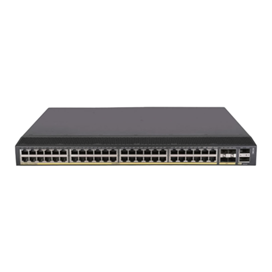
Appendix A Chassis views and technical specifications Chassis views S5850-54QS Figure 6-1 Front panel (1) 10/100/1000BASE-T autosensing Ethernet port (2) 10/100/1000BASE-T autosensing Ethernet port LED (3) SFP+ port (4) SFP+ port LED (5) QSFP+ port (6) QSFP+ port LED (7) System status LED (SYS) Figure 6-2 Rear panel (1) Grounding screw (2) Fan tray 1... -
Page 44: Technical Specifications
The SN serial number and MAC address of the S5850-54QS switch can be found on the serial label pull tab. The S5850-54QS switch comes with power module slot 1 empty and power module slot 2 installed with a filler panel. You can install one or two power modules for the switch as required. In Figure 6-2, two PSR150-A1 AC power modules are installed in the power module slots. - Page 45 Item Specification • AC input: 6.3 A, 250 V Melting current of power module fuse • DC input: 8 A, 250 V Operating temperature –5 to +45°C (23°F to 113°F) Relative humidity 5% to 95%, noncondensing Fire resistance compliance GB4943.1...
-
Page 46: Appendix B Removable Components
Appendix B Removable components Removable power modules You can install one power module, or two power modules for redundancy on the switch. The switch supports a mixture of an AC power module and a DC power module. The PSR150-A1 and PSR150-D1 power modules are available for the switch. Table 7-1 Removable power modules Power module Specifications... - Page 47 Item Specifications Fan speed 20000 R.P.M Max airflow 20 CFM Airflow direction Front to back (from the network port side to the power module side) Input voltage 12 V Maximum power consumption 9.8 W Reference H3C LSPM1FANSA & LSPM1FANSB Fan Trays User Guide...
-
Page 48: Appendix C Ports And Leds
Appendix C Ports and LEDs Ports Console port The switch has two console ports: a serial console port and a Mini USB console port. Table 8-1 Console port specifications Item Console port Mini USB console port Connector type RJ-45 Mini USB Type B Compliant standard EIA/TIA-232 USB 2.0... -
Page 49: Sfp+ Port
SFP+ port The switch provides four fixed SFP+ ports on the front panel. To connect the peer SFP+ ports over a long distance, use SFP/SFP+ transceiver modules and fibers. To connect the peer SFP+ ports over a short distance, use SFP/SFP+ cables. You can select the GE SFP transceiver modules and cables Table 8-3, 10-GE SFP+ transceiver modules in Table... - Page 50 GE SFP Central Cable/Fiber Modal transceiver wavelength Connector type and bandwidth transmission module and (nm) diameter (µm) (MHz × km) distance cable -SM1550 9/125 miles) SFP- GE-LX • TX: 1310 must Single-mode, -SM13 10 km (6.21 miles) • 9/125 RX: 1490 10-BI these transc...
-
Page 51: Qsfp+ Port
Table 8-5 SFP+ cables available for the SFP+ ports Cable description Cable length LSWM1STK 0.65 m (2.13 ft) LSWM2STK 1.2 m (3.94 ft) LSWM3STK 3 m (9.84 ft) LSTM1STK 5 m (16.40 ft) Figure 8-1 SFP+ cable (1) Connector (2) Pull latch NOTE: •... - Page 52 Fiber type Central QSFP+ Modal wavelength transceiver Connector bandwidth transmission diameter module (MHz × km) distance (nm) (µm) Four lanes: • 1271. QSFP-40G-LR4-W Single-mode, • 1291. 10 km (6.21 miles) DM1300 9/125 • 1311. • 1331. Table 8-7 QSFP+ cables available for the QSFP+ ports QSFP+ cable Max transmission distance LSWM1QSTK0...
-
Page 53: 10/100/1000Base-T Autosensing Ethernet Port
Figure 8-3 40G QSFP+ to SFP+ cable (1) QSFP+ module (2) QSFP+ side pull tab (3) SFP+ side pull tab (4) SFP+ module NOTE: • As a best practice, use H3C QSFP+ transceiver modules, QSFP+ cables, or QSFP+ to SFP+ cables for the QSFP+ ports on the switch. -
Page 54: Leds
LEDs System status LED The system status LED shows the operating state of the switch. Table 8-10 System status LED description LED mark Status Description Steady green The switch is operating correctly. Flashing green (1 Hz) The switch is performing power-on self test (POST). Steady red The switch has failed the POST or is faulty. -
Page 55: Sfp+ Port Led
SFP+ port LED Table 8-13 SFP+ port LED description SFP+ port LED status Description Steady green A link is present on the port and the port is operating at 10 Gbps. Flashing green The port is sending or receiving data at 10 Gbps. Steady yellow A link is present on the port and the port is operating at 1 Gbps. -
Page 56: Appendix D Cooling System
Appendix D Cooling system To dissipate heat timely and ensure system stability, the switch uses high-performance cooling system. Consider the site ventilation design when you plan the installation site for the switch. The switch uses hot-swappable fan trays. You can provide airflow from the power module side to the port side or from the port side to the power module side for the switch by using different fan trays.
Need help?
Do you have a question about the H3C S5850 Series and is the answer not in the manual?
Questions and answers