Table of Contents
Advertisement
Quick Links
IMPORTANT
READ CAREFULLY BEFORE USE
SAVE FOR FUTURE REFERENCE
Osby Parca Tel. no.: +46 (0)479 177 00 | sales@osbyparca.se | www.osbyparca.se | Box 93, 283 22 Osby, SWEDEN
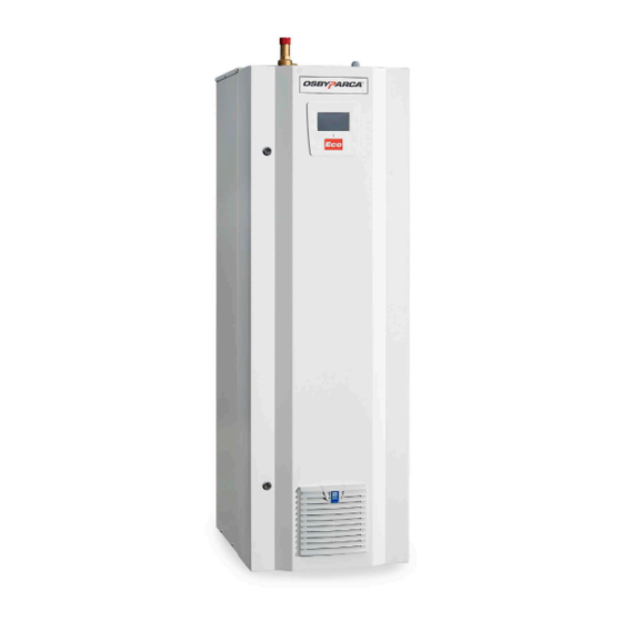
EL 160 Eco & EL 500 Eco
– Our new generation of electric boilers with touchscreen
Installation and Operating Instructions
The Professional's Choice Since 1935
1700 891 12-5
MADE IN
SWEDEN
EN
31/03/2021
Advertisement
Table of Contents

Related Manuals for Osby Parca EL 160 Eco


Summary of Contents for Osby Parca EL 160 Eco
- Page 1 The Professional’s Choice Since 1935 Installation and Operating Instructions IMPORTANT READ CAREFULLY BEFORE USE 1700 891 12-5 31/03/2021 SAVE FOR FUTURE REFERENCE Osby Parca Tel. no.: +46 (0)479 177 00 | sales@osbyparca.se | www.osbyparca.se | Box 93, 283 22 Osby, SWEDEN...
-
Page 3: Table Of Contents
5.1.1 Design data – EL 160 Eco __________________ 14 10.11.2 Heating curve adjustment _______________ 44 5.1.2 Pressure drop / Water resistance EL 160 Eco __ 14 10.11.3 Highest primary boiler temperature ________ 44 5.1.3 Dimensions & Connections EL 160 Eco S _____ 15 10.11.4 Lowest primary boiler temperature ________ 44... - Page 4 EL 160 Eco & EL 500 Eco...
- Page 5 Congratulations to your new electric boiler! You have just purchased an Osby Parca electric boiler which we hope you will be completely satisfied with. On the following pages, you can read about how to take care of your electric boiler.
-
Page 6: Important To Keep In Mind
Disposing of the product as household waste is not permitted. • It is of great importance that the product's electrical/electronic equipment is properly disposed of. EL 160 Eco & EL 500 Eco... -
Page 7: Installation
Note: At the standard boiler, the pressure switch connection is plugged. Nothing may be mounted there! Safety equipment must be mounted externally. The electric boiler is CE-approved as a unit and must not be altered. EL 160 Eco & EL 500 Eco... -
Page 8: Installation - Electrical
In order to get a calmer regulation it's recommended to increase the step time, how much is depending on the conditions (eg. size of water system). 3. Any external control is set according to section 9.8.1 and the manual for external control, e.g. a heat pump. EL 160 Eco & EL 500 Eco... -
Page 9: Overheating Protection
To restart the boiler, the circuit breakers inside the boiler must be reset and the alarm on the display acknowledged. 3.2 Circuit breaker (72-504 kW) The circuit breaker cannot be switched on until the triggered safeguard is reset. EL 160 Eco & EL 500 Eco... -
Page 10: Servicing
4.2 Replacing the air filter For EL 160 Eco and 500 Eco, the air filter must be replaced once per year. This may need to be done more fre- quently depending on the boiler room environment. The filter is replaced from the outside. -
Page 11: Settings Circuit Breaker
4.4 Settings circuit breaker Please fill in the table at installation and when the boiler is current limited, see magnification of image on p.12! NOTE! Applies to both models even if only shown in the "Instructions for re-tightening” for EL 160 Eco. Date... -
Page 12: Instructional Images For Re-Tightening
AF26 = 2,5 Nm AF12 = 1,5 Nm AF09 = 1,5 Nm 8. 2,8 Nm Magnification circuit breaker 7. 2,8 Nm 3. 8 Nm 4. 2,7 Nm 4. 13,5 Nm 5. 4,4 Nm 6. 2,7 Nm EL 160 Eco & EL 500 Eco... - Page 13 120-300 mm = 45 Nm 4. Immersion heaters: 1,8 Nm 5. Against rail: 20 Nm 6. 8 Nm 10. 26-30 Nm 9. 15 Nm 7-8. Contactores: AF52 = 4 Nm AF65 = 4 Nm EL 160 Eco & EL 500 Eco...
-
Page 14: Technical Data
Protection class IP21 Cable connection 2 x 120 mm Max.thermostat 105 +/- 5 °C Max preceded fuse for control 16 A circuit (230 V) 5.1.2 Pressure drop / Water resistance EL 160 Eco EL 160 Eco & EL 500 Eco... -
Page 15: Dimensions & Connections El 160 Eco S
5.1.3 Dimensions & Connections EL 160 Eco S (safety valve being discontinued on std versions) Supply flow conn. 50 (ext. thread) Return flow conn. 50 (ext. thread) Drainage R1” ext. Connection slot 4 x PG11 1070 1070 Flange opening 1 pc. FL-21... -
Page 16: Power Steps El 160 Eco
El 160 Eco 72 kW 400 V 3-phase 7700130-01/31 CURRENT Step 100% El 160 Eco 93 kW 400 V 3-phase 7700130-02/32 CURRENT Step 100% El 160 Eco 114 kW 400 V 3-phase 7700130-03/33 CURRENT Step 100% EL 160 Eco & EL 500 Eco... - Page 17 El 160 Eco 135 kW 400 V 3-phase 7700130-04/34 CURRENT Step 100% El 160 Eco 156 kW 400 V 3-phase 7700130-05/35 CURRENT Step 100% EL 160 Eco & EL 500 Eco...
-
Page 18: Technical Data El 500 Eco
Cable connection 2 x 240 mm Max.thermostat 105 +/- 5 °C Max preceded fuse for control 16 A circuit (230 V) 5.2.2 Pressure drop / Water resistance EL 500 Eco Pressure drop kPa Flow EL 160 Eco & EL 500 Eco... -
Page 19: Dimensions & Connections El 500 Eco S
Separate power supply 230 V 1 ~ required ceiling should not be less than 900 mm. for operating voltage. Pipe connections do not have the same loca- tion as previous Parca EL 350/500. EL 160 Eco & EL 500 Eco... -
Page 20: Power Steps El 500 Eco
El 500 Eco 204 kW 400 V 3-phase Relay 1 Relay 2 Relay 3 Relay 4 Relay 5 Step 100% 7700151-02, -32 El 500 Eco 252 kW 400 V 3-phase Relay Relay Relay Relay Relay Steg 100% EL 160 Eco & EL 500 Eco... - Page 21 Relay 4 Relay 5 Relay 6 Step 100% 7700151-04, -34 El 500 Eco 378 kW 400 V 3-phase Relay 1 Relay 2 Relay 3 Relay 4 Relay 5 Relay 6 Relay 7 Steg 100% EL 160 Eco & EL 500 Eco...
- Page 22 7700151-05, -35 El 500 Eco 441 kW 400 V 3-phase Relay 1 Relay 2 Relay 3 Relay 4 Relay 5 Relay 6 Relay 7 Relay 8 Step 100% EL 160 Eco & EL 500 Eco...
- Page 23 7700151-06, -36 El 500 Eco 504 kW 400 V 3-phase Relay Relay Relay Relay Relay Relay Relay Relay Relay Step 100% EL 160 Eco & EL 500 Eco...
-
Page 24: Example Of Power Limitation
5.2.5 Example of power limitation EL 160 Eco & EL 500 Eco... -
Page 25: Built-In Safety System (Option)
DN 25/32 6 bar Pressure transmitter ² DN 15 Overheating protection/ Max. thermostat Design Design in accordance with this description as well as SS EN 12828 closed systems, AFS 2002:1 and AFS 2016:6. EL 160 Eco & EL 500 Eco... -
Page 26: General
70 ° C. Before the boiler has cooled down, it is not possible to reset the circuit breaker and acknowledge the alarm on the display. To restart the boiler, the circuit breakers on the inside must be reset and the alarm on the display acknowledged. EL 160 Eco & EL 500 Eco... -
Page 27: Accessories
3 current sensors for secondary measurement, Max. 5A. Excl. current transformer 3364-3065 Cable flange FL21 1x16-300 mm² 3364-3066 Cable flange FL 21 2x16-300 mm² 6000-0501 Pipe system EL 500 Eco accessory 1 MW EL 160 Eco & EL 500 Eco... -
Page 28: Control System
8. Control system Osby Parca's new Eco series of electric boilers has an advanced but easy-to-use control system with a touchscreen via which all settings can be made. Control system functions: • monitors all electric boiler functions • allows for individual settings •... -
Page 29: Menu Overview
9. Menu overview Home screen Alarm menu Alarm Alarm Missing Missing Missing Operating time, energy calculator and highest boiler temperature menu Advanced settings menu EL 160 Eco & EL 500 Eco... - Page 30 Advanced settings menu Time, date and language menu Settings menu Define system menu Quick start menu EL 160 Eco & EL 500 Eco...
- Page 31 Setting type menu BMS communication menu EL 160 Eco & EL 500 Eco...
- Page 32 Service menu EL 160 Eco & EL 500 Eco...
- Page 33 Alarm menu Alarm Alarm Missing Missing Missing Alarm description menu Operating history menu Graph and chart menu EL 160 Eco & EL 500 Eco...
- Page 34 Define system menu EL 160 Eco & EL 500 Eco...
-
Page 35: Detailed Menu Descriptions
Opens the boiler's Settings menu. viewed, and the function can be overridden. Define system Home The heating system's structure can be set/ Press the Home button to return to the home changed here. screen. EL 160 Eco & EL 500 Eco... -
Page 36: Main Menu
The alarm can be reset If the fault cannot be reset, you will be advised to contact Support. This may happen if e.g. the relay board has broken. The alarm cannot be reset EL 160 Eco & EL 500 Eco... -
Page 37: Operational Information
Service is used for troubleshooting, diagnostics, history, program updates and to enter the reset PIN code*. PIN code is sent when the warranty registration is done. EL 160 Eco & EL 500 Eco... -
Page 38: Settings
10.8 Time & Language Language is selected by pressing the flags. To set the time, press OK and then use + and - to go up or down. The date is set in the same way. EL 160 Eco & EL 500 Eco... -
Page 39: Define System
• Reset max. temperature (PIN code) • Reset operating time calculator (PIN code) • Reset energy calculator (PIN code) • History (PIN code) • Service timer (PIN code) Also see chapter 4, Servicing. EL 160 Eco & EL 500 Eco... -
Page 40: Write Log To Usb
USB flash drive every 30 seconds for 24 hours. • Output relay 2 (on/off) • Output relay 3 (on/off) Used by Osby Parca for advanced analyses of • Output relay 4 (on/off) the boiler functions. • Output relay 5 (on/off) •... -
Page 41: Update Sw From Usb
Shows time remaining until the next service. The interval length between services is set here. This function can be deactivated after the warranty has expired. PIN code is sent when the warranty registration is done. EL 160 Eco & EL 500 Eco... -
Page 42: Bms Building Management Automation
Temp sensor to heat exchanger 0.1° Optional Active BMS alarms low value Bit encoded: Bit 0 alarm 0... Bit 15 alarm 15 Active BMS alarms high value Bit encoded Bit 0 alarm 16... Bit 4 alarm 20 EL 160 Eco & EL 500 Eco... -
Page 43: Outdoor Compensation - Utk
Once an existing sensor has been defined, the outdoor temperature will be displayed in the main menu. The heating curve defines the starting value for the boiler temperature. The outdoor temperature generates regulation of the boiler temperature. EL 160 Eco & EL 500 Eco... -
Page 44: Heating Curve Ascension/Inclination
In this example, the highest permitted primary flow temperature has been set to 55 °C. The lowest temperature is 27 °C (summertime compensation or systems unable to tolerate very high temperatures). Outdoor temperature EL 160 Eco & EL 500 Eco... -
Page 45: Diagram Boiler Temperature
The temperature is within the deadband changed. It is fixed at 16 seconds. The stage regulator does nothing. The temperature is lower than the deadband The output stage is connected during the step depending on the temperature's tendency. EL 160 Eco & EL 500 Eco... -
Page 46: Current Overload
For connection to the boiler, please refer to the actual model's wiring diagram. Current sensors are available from Osby Parca as boiler accessories. System-specific current transformer These current sensors can be ordered from Osby Parca. Art. no. 1118404-01 EL 160 Eco & EL 500 Eco... -
Page 47: Alarm Messages
When the circuit is broken the boiler quickly downshifts and enters OFF mode. When the circuit is closed again, the boiler first enters STANDBY mode and then, once the step duration permits, ON mode. EL 160 Eco & EL 500 Eco... -
Page 48: Sensor Resistances
5960 7080 8450 10130 12200 1115 14770 1443 18000 1883 22000 2478 27100 3289 33540 41800 52400 66200 84750 108000 139000 181000 238000 NOTE! The sensors must be disconnected before measuring the resistance! EL 160 Eco & EL 500 Eco... -
Page 49: Spare Parts Eco Series
Overheating protection (max.thermostat) Pressure transmitter (sender). 69-504 kW 3366-0601 Accessories: Receiver 3395-3253 and display 3395-3254 We also refer to the associated “ spare parts list ” at the wiring diagram for the actual boiler. EL 160 Eco & EL 500 Eco... -
Page 50: Ce Certificate
EN 61000-4-3 EN 61000-4-4 EN 61000-4-5 EN 61000-4-6 EN 61000-4-11 Osby 2018-01-05 ……………………………………… ……………………………………… Ort och datum / Place and date (Namnteckning / Signature) Dennis Eliasson General Manager Enertech AB Osby Parca Div. EL 160 Eco & EL 500 Eco... - Page 51 EN 61000-4-3 EN 61000-4-4 EN 61000-4-5 EN 61000-4-6 EN 61000-4-11 Osby 2020-01-27 ……………………………………… ……………………………………… Ort och datum / Place and date (Namnteckning / Signature) Dennis Eliasson General Manager Enertech AB Osby Parca Div. EL 160 Eco & EL 500 Eco...
-
Page 52: Appendices
14. Appendices • Circuit diagram • Warranty document Subject to errors or updates made after this edition. Enertech AB, Osby Parca div. Tel. no. +46 (0)479 177 00 | sales@osbyparca.se www.osbyparca.se Box 93 | SE-283 22 Osby | SWEDEN...
Need help?
Do you have a question about the EL 160 Eco and is the answer not in the manual?
Questions and answers