Table of Contents
Advertisement
Quick Links
Advertisement
Table of Contents

Related Manuals for THORLABS LM9LP


Summary of Contents for THORLABS LM9LP
- Page 1 LM9LP Pigtailed Laser Mount Operating Manual...
-
Page 2: Table Of Contents
4.2. RF Modulation ............................12 4.3. Status and Interlocks ..........................13 4.4. Maintaining the LM9LP ........................13 Part 5. Making Safety Interlock Connections ..................14 Part 6. Troubleshooting ........................15 Part 7. Specifications ..........................16 Part 8. Thermistor Data ........................18 Part 9. Mechanical Drawing .........................19 Part 10. -
Page 3: Part 1. Safety
All statements regarding safety of operation and technical data in this instruction manual will only apply when the unit is operated correctly. WARNING This unit must not be operated in explosive environments WARNING Avoid Exposure – Laser Radiation Emitted from apertures 20913-D02 Rev F, June 23, 2014 Page 3 www.thorlabs.com... -
Page 4: Part 2. Description
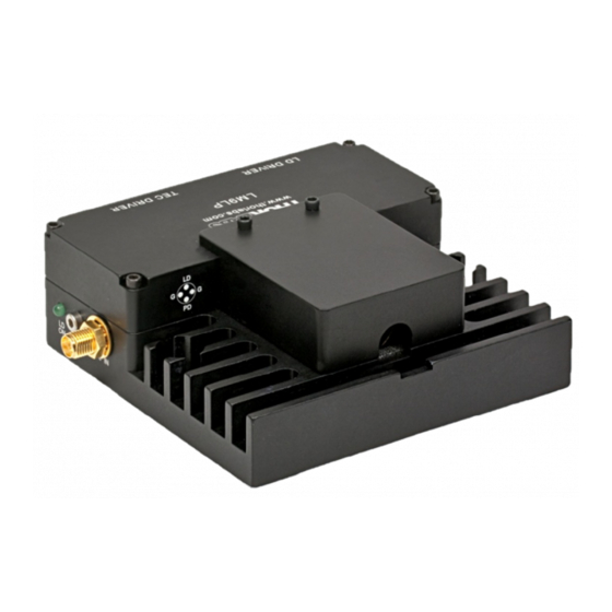
• Clamshell Design Eliminates Thermal Gradients Across Diode • Bias-T Adapter for RF Modulation of Laser Current >1 GHz Thorlabs' LM9LP is an LD and TEC mount designed for use with all of our 3- and 4-pin pigtailed diodes . The compact housing protects the pigtail from physical damage, while also offering excellent thermal characteristics. -
Page 5: Part 3. Setup
• Determine the laser pin configuration from the laser diode manufacturer’s data sheets and set the LD (Laser Diode) and PD (Photodiode) switches on the side of the LM9LP according to the diagram and picture below. Case Case... - Page 6 The other laser and photodiode pin will be isolated from the case. The LM9LP was designed to operate the laser case at ground potential therefore this common pin will be inserted into either of the holes marked ‘G’...
-
Page 7: Special Note For 4-Pin Laser Diodes
Pigtailed LD Mount 3.2. Special Note for 4-pin Laser Diodes The LM9LP also supports 4-pin laser diodes. Insert the laser into the 4-pin socket and note which laser pin is in the 12 o’clock position (laser anode or cathode). Also, note which photodiode pin is in the 6 o’clock position (anode or cathode). -
Page 8: Laser Diode Current Controller Connection
3.4. Laser Diode Current Controller Connection Using the Thorlabs LDC/ITC Series Laser Controllers: • The LM9LP is compatible with all Thorlabs LDC LD controllers and ITC series combination controllers (LD and TEC). Appropriate cables with DB9 connectors are included with Thorlabs controllers and ensure that the controllers cannot be connected incorrectly. -
Page 9: Using A Third-Party Laser Controller
Signal Description This pin is the input to the LD Status indicator and interlock circuits. Interlock and When using Thorlabs’ LDC controllers, no external circuitry is Status Pin required. To use these features with third-party controllers, please (LDC Specific) refer to page 13. -
Page 10: Tec Controller Connection
3.6. TEC Controller Connection Using Thorlabs’ TED Series TEC Controllers: • The LM9LP is compatible with all Thorlabs TED series temperature controllers and ITC series combination controllers (LD and TEC). The TED series is shipped with a mating DB9 cable that plugs directly into the controller and laser mount. -
Page 11: Tec Lockout And Ground Jumpers
JMP2 disconnected. To close this connection, remove the cover of the unit and place the blue jumper onto both pins of the JMP2 header. JMP1 JMP2 Jumpers Figure 7: 20913-D02 Rev F, June 23, 2014 Page 11 www.thorlabs.com... -
Page 12: Part 4. Operation
Part 4. Operation 4.1. General Once the laser is mounted in the LM9LP and a Laser Diode Current Controller and TEC Controller are connected, the device is ready to operate. Please refer to the operating instructions for the laser and temperature controller for specific operating instructions. -
Page 13: Status And Interlocks
There are no serviceable parts in the LM9LP. The housing may be cleaned by wiping with a soft, damp cloth. If you suspect a problem with your LM9LP, please call Thorlabs and an engineer will be happy to assist you. -
Page 14: Part 5. Making Safety Interlock Connections
Pigtailed LD Mount Part 5. Making Safety Interlock Connections The LM9LP is equipped with a Remote Interlock connector located on the side panel. In order to enable the laser source, a short circuit must be applied across the terminals of the Remote Interlock Connector. -
Page 15: Part 6. Troubleshooting
LD polarity switch setting on the rear panel of your LDC series laser diode controller. If you still have problems or questions regarding the operation of your LM9LP, please feel free to call Thorlabs and ask for Technical Support. -
Page 16: Part 7. Specifications
Pigtailed LD Mount Part 7. Specifications Performance Specifications Lasers Supported Thorlabs LPS, LPS-PM, and LPM Series 500 mA Maximum Laser Current A, B, C, D, E, and H (see page 4 for schematics) Laser Pin Configurations 200 kHz to >1 GHz... - Page 17 Pigtailed LD Mount RF modulation of the LM9LP can be accomplished in one of two ways. For low frequencies (below ~200 kHz), the RF modulator should be connected to the LD controller. Figure 8 shows the performance of Thorlabs’ LDC202C and ITC4005 when used with the LM9LP and RF modulation.
-
Page 18: Part 8. Thermistor Data
2.1400943E-06 -7.2405219E-08 0.3599 to 0.06816 3.3530481E-03 2.5420230E-04 1.1431163E-06 -6.9383563E-08 0.06816 to 0.0187 3.3536166E-03 2.5377200E-04 8.5433271E-07 -8.7912262E-08 Temperature can be calculated using the following equation: + + ln ( + 0 ln 20913-D02 Rev F, June 23, 2014 Page 18 www.thorlabs.com... -
Page 19: Part 9. Mechanical Drawing
Pigtailed LD Mount Part 9. Mechanical Drawing 20913-D02 Rev F, June 23, 2014 Page 19 www.thorlabs.com... -
Page 20: Part 10. Regulatory
10.1. Waste Treatment is Your Own Responsibility If you do not return an “end of life” unit to Thorlabs, you must hand it to a company specialized in waste recovery. Do not dispose of the unit in a litter bin or at a public waste disposal site. -
Page 21: Part 11. Thorlabs Worldwide Contacts
Pigtailed LD Mount Part 11. Thorlabs Worldwide Contacts For technical support or sales inquiries, please visit us at www.thorlabs.com/contact for our most up-to- date contact information. USA, Canada, and South America UK and Ireland Thorlabs, Inc. Thorlabs Ltd. sales@thorlabs.com sales.uk@thorlabs.com techsupport@thorlabs.com... - Page 22 www.thorlabs.com...
Need help?
Do you have a question about the LM9LP and is the answer not in the manual?
Questions and answers