Table of Contents
Advertisement
Quick Links
This guide is for quick installing and connecting the G-Tect VCA-Bridge. For more details, please refer to the User's
Manual in the supplied CD.
About the manual
This manual provides the instructions for the quick installation and basic configuration of your IP device. For more
detailed information about the configuration, refer to the device's user manual. Before installing and operating the
unit, please read this manual thoroughly and keep it for future reference.
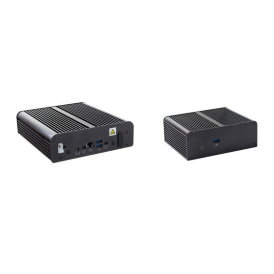
Part names and Functions G-Tect VCA Bridge/4
Please check the name and the position of each part by referring to the following image.
[ Front ]
❶
Power Button: Pressing the button turns on the device when the DC12V power is connected to the device.
❷
USB port 1: Connector for an external device such as a USB stick or mouse
[ Back ]
❶
DC12V power connector: Connector for DC12V power supply
❷
Terminal Connector: Connector for two digital inputs/outputs and an RS-485 device
❸
HDMI connector: An HDMI cable connector for a monitor
❹
Ethernet port: RJ45 LAN connector for 10/100 Base-T Ethernet
USB port 2&3: Connector for an external device such as a USB stick or mouse
❺
❻
Audio Jack: Connector for audio input(MIC)/output(headphone)
Part names and Functions G-Tect VCA Bridge/16
Please check the name and the position of each part by referring to the following image.
G-Tect VCABridge/4 + G-Tect VCABridge/16 Installation Quick Guide
[ Front ]
❶
Power Button: Pressing the button turns on the device when the DC12V power is connected to the device.
❷
HDD status LED: The LED blinks orange when the hard disk drive is accessed for Read/Write.
❸
Power status LED: The blue light indicates whether the device is powered on.
❹❺
USB port 1&2: Connector for an external device such as a USB stick or mouse
❻
Terminal Connector: Terminal connector for four digital inputs/outputs, one audio input/output and two of RS-485
[ Back ]
❶
DC12V power connector: Connector for DC12V power supply
❷❻
Mini DisplayPort 1&2: Connector for a monitor
❸
Ethernet port: RJ45 LAN connector for 10/100Base-T Ethernet
❹❺
USB port 3&4: Connector for an external device such as a USB
Installation
There are three types of installation: Wall mount with brackets, free standing with spacers, and outdoor installation
within a box.
[ Wall Mount ]
Step1) Unscrew all the bolts on the bottom of the device and
take them out.
Step2) Insert each bracket (included) to the loosened bolts on
both sides of the bottom by referring to the image on the right
and tighten them to fix the brackets to the device.
Step3) Drill four holes on the wall based on the holes'
locations on the fixed brackets, and insert the plastic anchors
tightly into the holes.
Step4) Fix the device to the wall with the M4x20 bolts (included)
by inserting the bolts into the bracket's holes and tightening
them through the plastic anchors.
[ Free Standing ]
Step1) Loosen all the bolts on the bottom of the device, and
take them out.
Step2) Insert each rubber washer (included) and spacer
(included) to the 6x32UNCx12 bolts (included), and tighten the
bolts firmly to the bottom of the device. Then, the spacers
supported by the bolts will be used as the feet of the device for
free standing.
Advertisement
Table of Contents

Subscribe to Our Youtube Channel
Related Manuals for Geutebruck G-Tect VCABridge/4


Summary of Contents for Geutebruck G-Tect VCABridge/4
- Page 1 G-Tect VCABridge/4 + G-Tect VCABridge/16 Installation Quick Guide This guide is for quick installing and connecting the G-Tect VCA-Bridge. For more details, please refer to the User’s [ Front ] Manual in the supplied CD. ❶ Power Button: Pressing the button turns on the device when the DC12V power is connected to the device.
- Page 2 G-Tect VCABridge/4 + G-Tect VCABridge/16 Installation Quick Guide [ Outdoor Application ] The installation below is for outdoor applications with protection from rain, dust and etc. 1 CH Encoder 1 CH Encoder Step1) Place the device to the breadboard in the box.
Need help?
Do you have a question about the G-Tect VCABridge/4 and is the answer not in the manual?
Questions and answers