
Related Manuals for ATIM Cloud Wireless Series

Summary of Contents for ATIM Cloud Wireless Series
- Page 1 Concerned models: ACW/SF8-MR2 ACW/LW8-MR2 ATIM Radiocommunications www.atim.com Chemin des Guillets [Tapez ici] info@atim.com 38250 Villard de Lans +33 4 76 95 50 65 France...
-
Page 2: Table Of Contents
ABLE OF ONTENTS Disclaimer ............................. 2 Trademarks and copyright ......................2 Declaration of compliance ......................3 Environmental recommendations ....................3 Explosive atmosphere ........................3 Environment ............................. 3 Radio ..............................4 Prelude ..............................5 ACW-MR Product line ........................5 Product Identification ........................6 Technical specifications ...................... -
Page 3: Disclaimer
Disclaimer The information contained in this document is subject to change without warning and does not represent a commitment on the part of ATIM radiocommunications. ATIM radiocommunications provides this document ‘as-is’ with no warranty of any kind, express or implied, including but not limited to implied warranties of merchantability or fitness for a particular purpose. -
Page 4: Declaration Of Compliance
Declaration of compliance All ACW Atim Cloud Wireless® products comply with the regulatory requirements of the R&TTE Directive (1999/5/EC), article 3: 1 SAFETY (Article 3.1a of the 1999/5/EC Directive) NF EN60950-1 Ed. 2006/A1:2010/A11:2009/A12:2011 (health) EN62479: 2010 (power <20mW) or EN62311:2008 (power > 20mW) 2 Electromagnetic compatibility (Article 3.1b of the 1999/5/EC Directive) -
Page 5: Radio
General hazard – Failure to follow the instructions presents a risk of equipment damage. Electrical hazard – Failure to follow the instructions presents a risk of electrocution and physical injury. Direct-current symbol WARNING: do not install this equipment near any source of heat or any source of humidity. WARNING: for your safety, it is essential that this equipment be switched off and disconnected from mains power before carrying out any technical operation on it. -
Page 6: Prelude
Prelude This user guide describes the ATIM ACW-MR products functionalities. It explains operating, configuration and installation modes in functions of different use cases. ACW-MR Product line ACW-MR product line regroups different types of radio equipment which allow pulse metering, bang-bang control and fraud detection. -
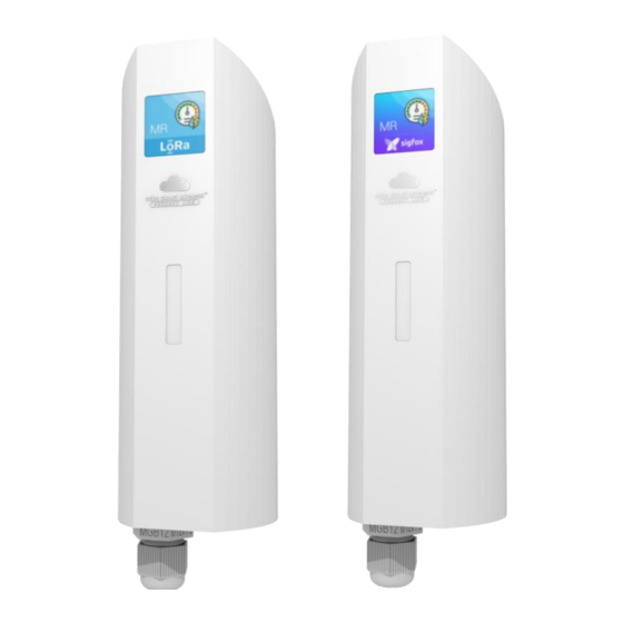
Page 7: Product Identification
The ACW-MR1-ELEC is delivered with an integrated optical sensor, this plug and play device monitores remotely the consumption of an LED optical electrical meter (eg: Linky meters, PME-PMI meters). It is delivered and pre-set to memorize the consumption index every 10 minutes and send the last 6 every hour. -
Page 8: Technical Specifications
1. Technical specifications Dimensions 177 x 55 x 55 mm Antenna Integrated (¼ wave) -20°C to +55°C (operating) Temperature -40°C to +70°C (storage) Mounts to Wall, Mast, DIN-Rail Shaft Sealing IP 65 2 packs of 2 batteries equivalent to 14.4 Battery Weight 160 g... -
Page 9: B) "Bang-Bang Detection" Mode
The device monitors both inputs. For these inputs, it increments the index for each pulse received. Periodically (once per hour or once per day for example), it sends both indexes in the same frame. Eco meter reading • The sensor does monitor only one input and it stores the index at a determined frequency (every 10 minutes for example). - Page 10 inputs. The bang-bang detection mode can be set up among the following configurations: Inputs state checking every minute • Contact closing detection • Contact opening detection • Contact closing or opening detection • ATIM_ACW-MR2_UG_EN_V1.0...
-
Page 11: Installation
3. Installation You may open the casing in order to access the configuration switches and the terminal block connection. Please insert a screwdriver in the small slot and bend downwards to lift up the internal strip (cf. photo). Then, pull the back side in order to divide the casing in two parts. - Page 12 Batteries’ polarity is shown on the printed circuit board. The positive + pole is orientated towards the terminal block, the negative – pole towards the antenna. An isolation strip is to be taken off one of the battery terminals for the first use. In case of the addition of an extra battery;...
-
Page 13: A) Connection To A Pulse Meter Reading
a) Connection to a pulse meter reading The amount of cables and their color depend on the pulse emitter type installed on the meter. Please refer to the emitter guide in order to verify the connection. 2 cables connection (pulse emitter without anti-fraud output) Pulse cable Ground cable Please note that in particular cases, pulse and mass cables are undifferentiated. -
Page 14: B) Connection To 2 Meters
b) Connection to 2 meters The amount of cables and their color depend on the pulse emitter type installed on the meter. Please refer to the emitter guide in order to verify the connection. 2x2 cables Connection Ground cable, meter 1 Pulse cable, meter 1 Pulse cable, meter 2 Ground cable, meter 2... -
Page 15: Power Failure Magnet
You will need to append the magnet for 30 seconds in order to restart correctly. 5. Gas meter reading connection ATIM can provide a cable (ref. CAB/MTRGAZ1) appropriate for gas meters with a M16 IP40 connector, with the bellow characteristics:... - Page 16 6 armored wires cable of 20 AWG section and a length of 2 meters. Wire Color Signal Brown Monitoring + White GND - Monitoring Grey Metering 2 + DIN female connection seen from the external Blue Metering 1 + side Yellow GND - Metering 2 Green...
-
Page 17: Optical Sensor Connection In " Elec " Mode
6. Optical sensor connection in « elec » mode The ACW/XXX-MR1-ELEC reference is delivered with a preinstalled Fluidia optical sensor (4 wired cable with 30 centimeters length). GND - Metering Power GND - Power Pulse 1 + Wire Color Signal Black Power Metering 1 +... - Page 18 The configuration is read at the starting of the device. The following table lists the different operating modes that can be set up. Standard reading mode: periodic reading of both meter inputs (even if one • unique input is used) with a systematic data emission. Change of state detection mode: state emission of both inputs when a change •...
- Page 19 Radio emission period (METER READING frame): 10 min Radio emission period (METER READING frame): 30 min Radio emission period (METER READING frame): 1 h STANDARD Radio emission period (METER READING frame): 3 h METER READING MODE Radio emission period (METER READING frame): 6 h Radio emission period (METER READING frame): 12 h Radio emission period (METER READING frame): 24 h Radio emission period (METER READING frame): 48 h...
-
Page 20: B) Downlink Frames Configuration
Downlink operation mode is explained in the ATIM_ACW-DLConfig_UG_FR_v1.1 document, related to version V1.1 of Downlink protocol ATIM. Downlink protocol ATIM V1.1, shared between all ACW Product Line devices, describes how to realize the following actions: Ask for an ACW products restart •... - Page 21 Operating mode • Parameter Code (1 Parameter Value (2 octets) octet) 0x0A Possible values are: 0x00 = standard meter reading with emission every 10 minutes 0x01 = standard meter reading with emission every 6 hours 0x02 = standard meter reading with emission every hour 0x03 = standard meter reading with emission every 3 hours 0x04 = standard meter reading with emission every 30 minutes...
- Page 22 every 6 hours 0x0F = N/A0x10 = Use DIP switch configuration Reminder By default, the product uses the DIP switch configuration until a downlink frame has been done. If a configuration via downlink has been made, at the next restart, this configuration will be used.
- Page 23 The indexes of meters 1 and 2 can be set on a single command, with values of your choice, within the interval from 0 to 4294967295. Command to send Parameter Value (4 octets) C1090Cxxxxxxxxyyyyyyyy Possible values for xxxxxxxx and yyyyyyyy (in hexadecimal): 0x00000000 0xFFFFFFFF...
-
Page 24: Sigfox - Lorawan Frame Format
Delta 5 SIGFOX (12bits) (12bits) (12bits) (12bits) (12bits) (Tref-60min) (Tref-120min) (Tref-180min) (Tref-240min) (Tref-300min) *Tref = moment of emission 9. Technical Support For any further information or technical issues, you may contact our technical support team on this webpage : www.atim.com/fr/technical-support ATIM_ACW-MR2_UG_EN_V1.0...
Need help?
Do you have a question about the Cloud Wireless Series and is the answer not in the manual?
Questions and answers