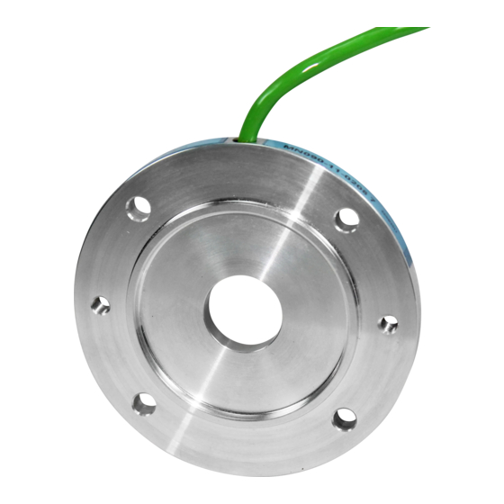
Summary of Contents for BEGE MIG BASIC
- Page 1 POWER TRANSMISSION Installation manual BEGE MIG Encoders ® Installationsanleitung BEGE MIG Drehgeber ® MIG BASIC MIG NOVA+ MIG AST v 1.1 | 10-2020 EN · DE YOUR DRIVE. OUR TRANSMISSION. POWER TRANSMISSION...
- Page 2 IEC/NEMA-Standard Baugrö ß en Platzsparendes Design Technical data subject to modification Copyright BEGE, whose property this document remains. No part thereof may be disclosed, copied, duplicated or in any other way made use of except with the written approval of BEGE.
-
Page 3: Table Of Contents
Montage MIG® Drehgeber MIG BASIC INCREMENTAL ENCODERS MIG BASIC INKREMENTAL DREHGEBER Technical data MIG BASIC Technische Daten MIG BASIC Terminals & signals MIG BASIC Anschlussbelegung und Signale MIG BASIC MIG NOVA+ INCREMENTAL ENCODERS MIG NOVA+ INKREMENTAL DREHGEBER Technical data MIG NOVA+ Technische Daten MIG NOVA+ Terminals &... -
Page 4: Safety Notes
Entfernung der notwendigen Schutzabdeckungen • prohibited removal of the necessary protective covers BEGE haftet nicht für Fehler und möglicherweise dadurch BEGE can not be held responsible for any injury or damage verursachte Schäden oder Mängel. caused. Sicherheitshinweise zur Installation Installation safety notes •... -
Page 5: Installation Notes
INSTALLATION NOTES INSTALLATIONSHINWEISE Before commissioning, all required wires are to be connected Vor Inbetriebnahme sind alle benötigten Kabeladern laut according to the instruction manual. Datenblatt anzuschließen! Please isolate unused connection wires to protect against Isolieren Sie alle nicht benötigten Enden sauber, um short-circuits. -
Page 6: Installation Of The Mig Encoder
INSTALLATION OF THE MIG ENCODER · MIG DREHGEBER MONTAGE <20 >20 Please ensure the following mounting procedure to avoid Um Beschädigungen am Drehgeber zu vermeiden bitte damage to the magnet ring and the sensor: folgende Schritte bei der Montage beachten: 1. - Page 7 Attention: Magnet rings are to be handled carefully Achtung: Magnetringe sind vorsichtig zu handhaben – Do not use magnetised tools – Keine magnetisierten Werkzeuge benutzen – Protect external cylinder surface against damage – Äußere Zylinderfläche vor Beschädigung schützen – Prevent contact with other magnetised parts –...
-
Page 8: Mig Basic Incremental Encoders
Hydromotor, erhöhter Temperaturbereich, abweichende Rotorbohrung, kundenspezifischer Flansch Sonderlängen auf Anfrage Different lengths on request IP67 abhängig von der Abdichtung zwischen Motor- IP67 depending on the sealant used between motor and und Getriebeflansch machine flange MIG BASIC INCREMENTAL ENCODERS · MIG BASIC INKREMENTAL DREHGEBER... -
Page 9: Terminals & Signals Mig Basic
Achtung: Bitte beachten Sie die allgemein applicable notes for a correct installation and use gültigen Hinweise zur korrekten Installation und of the encoder on page 5. Verwendung des Gebers auf Seite 5. SIGNAL EVALUATION · SIGNALAUSWERTUNG MIG BASIC INCREMENTAL ENCODERS · MIG BASIC INKREMENTAL DREHGEBER... -
Page 10: Mig Nova+ Incremental Encoders
MIG NOVA+ INCREMENTAL ENCODERS MIG NOVA+ INKREMENTAL DREHGEBER ELECTRICAL & MECHANICAL VALUES · ELEKTRISCHE & MECHANISCHE DATEN Connecting voltage U Spannungsversorgung U 5 – 24 VDC Max. impulse frequency Max. Impulsfrequenz ≤ 100 kHz 6000 min (1024 impulses) Max. speed Max. -
Page 11: Terminals & Signals Mig Nova
MIG NOVA+ TERMINALS · ANSCHLUSS Terminal · Anschluss Ā brown white yellow green pink grey Cable · Kabel braun weiß gelb grün rosa grau brown blue white black 4-pin plug · Stecker 4-polig braun blau weiß schwarz Attention: Please refer to the general Achtung: Bitte beachten Sie die allgemein applicable notes for a correct installation and use gültigen Hinweise zur korrekten Installation und... -
Page 12: Technical Data Mig Ast
MIG AST ABSOLUTE SINGLE-TURN ENCODERS MIG AST ABSOLUT SINGLE-TURN DREHGEBER ELECTRICAL & MECHANICAL VALUES · ELEKTRISCHE & MECHANISCHE DATEN Connecting voltage U Spannungsversorgung U 5 – 24 VDC Max. speed Max. Drehzahl 6000 min ≤ 200 mA @ U = 5 VDC Output capacities Belastbarkeit der Ausgänge ≤... -
Page 13: Terminals & Signals Mig Ast
MIG AST TERMINALS · ANSCHLUSS Terminal · Anschluss Error brown white green yellow grey pink Cable · Kabel braun weiß grün gelb grau rosa Attention: Please refer to the general Achtung: Bitte beachten Sie die allgemein applicable notes for a correct installation and use gültigen Hinweise zur korrekten Installation und of the encoder on page 5. -
Page 14: Calibrating The Mig Ast
CALIBRATING THE MIG AST · KALIBRIEREN MIG AST Hardware: IC334 Adaptor and MB5U USB or link/URL to the software download USB oder Link / URL zum Software-Download Calibrating can be first undertaken after successfully Das kalibrieren erfolgt nach erfolgreicher Montage des MIG- installing the MIG AST to your drive unit (see instruction AST auf Ihren Antrieb. - Page 15 CALIBRATING THE MIG AST · KALIBRIEREN MIG AST 3 Click ‘Restart’ to restart the computer 3 Klicken Sie auf “Neustart”, um den Computer neu zu 3 After restarting, go to the directory and click starten ‘USB_MB5U_driver_IC31200.exe’ 3 Nach erfolgten Neustart, nochmals in Verzeichnis ‘USB_MB5U_driver_IC31200.exe’...
- Page 16 CALIBRATING THE MIG AST · KALIBRIEREN MIG AST Click on ‘Disconnected’ button to connect software with interface and encoder. Klicken Sie auf die Schaltfläche “Disconnected”, um die Software mit der Schnittstelle und dem Encoder zu verbinden 1. By clicking the button ‘Disconnected’ the software 1.
- Page 17 CALIBRATING THE MIG AST · KALIBRIEREN MIG AST Change direction if necessary. Set drive to desired position and stop. Ändern Sie gegebenenfalls die Richtung. Fahren Sie in die gewünschte Position und halten Sie an. Position / Status Position / Status Direction CW / CCW Direction ändern CW / CCW You can change the direction of rotation between clockwise...
- Page 18 .TOGETHER YOUR DRIVE. OUR TRANSMISSION. BEGE Power Transmission Anton Philipsweg 30 2171 KX Sassenheim The Netherlands +31 252-220 220 sales@bege.nl WWW.BEGE.NL...


Need help?
Do you have a question about the MIG BASIC and is the answer not in the manual?
Questions and answers