
Related Manuals for Eagle Eye LB-60-30

Summary of Contents for Eagle Eye LB-60-30
- Page 1 LB-60-30 LOAD BANK MANUAL CONTAINS OPERATING INSTRUCTIONS PARTS LIST WIRING DIAGRAMS SERVICE INSTRUCTIONS Eagle Eye Power Solutions, LLC. 4031 W Kiehnau Ave Milwaukee, WI 53209 Eagle Eye Power Solutions, LLC.
- Page 2 TEMPORARY USE ONLY. THE LOAD RESISTORS ARE ENERGIZED WHEN THE RATE SWITCH IS OFF; THEREFORE DO NOT INSERT ANY OBJECTS IN THE GRILL ASSEMBLY. DO NOT BLOCK THE AIR FLOW OR USE IF THE AIR FLOW IS REVERSED. Eagle Eye Power Solutions, LLC.
-
Page 3: Table Of Contents
MANUAL FOR LB-60-30 LOAD BANK TABLE OF CONTENTS SUBJECT SECTION PAGE DESCRIPTION PURPOSE OF LOAD BANK 1 - 1 RATING OF LOAD BANK 1 - 2 LOAD BANK DESCRIPTION FIGURE 1 - 1 1 - 3 CONTROL PANEL LAYOUT FIGURE 1 - 2... -
Page 4: Description
1-2 RATING OF LOAD BANK: The LB-60-30 is rated at 30 KW full loads with all six load steps turned on. The load steps are 1KW, 2KW, 2KW, 5KW, 10KW and10KW. This gives a 0-30KW range in 1KW steps. -
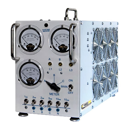
Page 5: Control Panel Layout Figure
2KW 2KW 5KW 10KW 10KW RATE SWITCHES METER TEST JACKS FIGURE 1 - 2 1-4 CONTROL DESCRIPTION: The following is a description of the controls on the control panel (see figure 1-2 on page 2. Eagle Eye Power Solutions, LLC. - Page 6 METER TEST JACKS - This provides a place to connect an external meter. There is a test jack for each cable pin. POWER RECEPTACLE - The power cable from the equipment to be tested is plugged into the load bank through the receptacle. Eagle Eye Power Solutions, LLC.
-
Page 7: Operation
2-5 SHUTTING DOWN - After turning the rate off, allow the load bank to cool down before turning the power unit off. Turn the power unit off and disconnect the power cable plug. Eagle Eye Power Solutions, LLC. -
Page 8: Testing 240Vac Single Phase
2-5 SHUTTING DOWN - After turning the rate off, allow the load bank to cool down before turning the power unit off. Turn the power unit off and disconnect the power cable plug. Eagle Eye Power Solutions, LLC. -
Page 9: Testing 208Vac Three Phase
2-5 SHUTTING DOWN - After turning the rate off, allow the load bank to cool down before turning the power unit off. Turn the power unit off and disconnect the power cable plug. Eagle Eye Power Solutions, LLC. -
Page 10: Parts Information
PARTS INFORMATION CONTROL PANEL PARTS AC AMPS AC VOLTS HERTZ MAIN METER 2KW 2KW 5KW 10KW 10KW FIGURE 3 - 1 Eagle Eye Power Solutions, LLC. - Page 11 MR-60 55-65 HERTZ FREQUENCY METER HD-25 HANDLE KN-10 POINTER KNOB SW-13 ROTARY SWITCH 3POSITION 1 POLE SW-21 TOGGLE SWITCH SPST TP-10 TEST PINS SW-22 TOGGLE SWITCH DPST LT-10 115V AMBER LIGHT LT-15 115V RED LIGHT Eagle Eye Power Solutions, LLC.
-
Page 12: Interior Parts List
INTERIOR PARTS LAYOUT 24,25 9,10 16,17, FIGURE 3 - 2... - Page 13 SNAP IN FUSE HOLDER FS-10 FUSES, 1A GLASS FS-12 FUSE, 5A, GLASS CT-10 100:5 CURRENT TRANSFORMER SR-25 SCR 12 AMPS RESISTOR 10KΩ 1/2 WATT-ADJ RC-09 RD-12 ZENER DIODE 120V 5W RD-10 DIODE 1A GL-24 RESISTOR GRILL Eagle Eye Power Solutions, LLC.
-
Page 14: Fan Panel Parts List
FAN PANEL PARTS LAYOUT 10 1 FIGURE 3 - 3 Eagle Eye Power Solutions, LLC. - Page 15 TM-10 TERMINAL STRIP 11 POS RD-06 RECTIFIER 6A CP-35 CAPICATOR, 350UF, 160VDC FP-28 ALUM. FAN PANEL GL-10 FAN GRILL CHROME V-MERRILL (B-22662) FN-25 24VDC FAN V-EBM (W2G110-AK43-31) TS-15 THERMAL SWITCH V-GEMLINE (L-145) SW-12 TILT SWITCH Eagle Eye Power Solutions, LLC.
- Page 16 5. Rivet the new fan back to the fan panel. 6. Place the fan panel back on the load bank. Make sure that the wires are on the proper terminals. Eagle Eye Power Solutions, LLC.
- Page 17 9- WH T BL U F6- 10- - 9- WH ITE SW11 12 WH ITE 11- RED 1R ED AC RT1 BL K G-RE D RE D 10 -WHT 12 -WHT FIGURE 5 - 2 Eagle Eye Power Solutions, LLC.
- Page 18 INTERIOR WIRING Eagle Eye Power Solutions, LLC.
- Page 19 RESISTOR 5.6K OHM 5 WATT RECEPTACLE, 4 POLE RECTIFIER 6A SCR 12AMPS SWITCH, TOGGLE DPST SWITCH, ROTARY 3POS 1 POLE SW3-8 SWITCH, TOGGLE SPST SWITCH, AIR FLOW SW10 THERMAL SWITCH 155° SW11 MERCURY SWITCH TP1-4 TEST PINS FIGURE 5-3 Eagle Eye Power Solutions, LLC.
- Page 20 Contact EEPS Eagle Eye Power Solutions, LLC. 4031 W Kiehnau Ave. Milwaukee WI, 53209 TEL: 1-877-805 EEPS (3377) FAX: 1-414-962-3660 www.eepowersolutions.com info@eepowersolutions.com Eagle Eye Power Solutions, LLC.
Need help?
Do you have a question about the LB-60-30 and is the answer not in the manual?
Questions and answers