
Related Manuals for CTC Union Pro SC901 Series

Summary of Contents for CTC Union Pro SC901 Series
- Page 1 SC901 Series Hazardous Area, Factory Set Vibration Signal Conditioners M N X 1 0 0 0 1 , R E V C ● 2 / 8 / 2 0 1 2 Connection Technology Center, Inc. ● 7939 Rae Boulevard ● Victor, NY 14564 ● (585) 924-5900...
-
Page 2: Table Of Contents
C O N T E N T S SECTION 1: OVERVIEW…………………………………………………………………………………………………………………..….. 4 Introduction………………………………………………………………………………………………………………………………… 4 Product Selection Guide…………………………………………………………………………………………………………… 5 Specifications………………………………………………………………………………………………………………………………. 6 Environmental……………………………………………………………………………………………………………………….. 6 Electrical…………………………………………………………………………………………………………………………………… 6 Physical…………………………………………………………………………………………………………………………………….. 6 SECTION 2: INSTALLATION………………………………………………………………………………………………………………….. 7 Description……………………………………………………………………………………………………………………………….….. 7 Mounting Instructions…………………………………………………………………………………………………………….….8 Electrical Connections………………………………………………………………………………………………………………..8 SECTION 3: OPERATION…………………………………………………………………………………………………………….…………10 ... - Page 3 F I G U R E S Figure 1. (SC901 Series Selection Guide)………………………………………………………………………………………..….. 4 Figure 2. (Mounting Dimensions)……………………………………………………………………………………….……………… 8 Figure 3. (Front Panel)……………………………………………………………………………………………………………….………. 9 M N X 1 0 0 0 1 , R E V C ● 2 / 8 / 2 0 1 2 Connection Technology Center, Inc. ● 7939 Rae Boulevard ● Victor, NY 14564 ● (585) 924-5900...
-
Page 4: Introduction
F I G U R E S Introduction This document contains information on the operation, installation and maintenance of the SC901 Series Signal conditioner for Hazardous Areas. The SC901 Series signal conditioner accepts input from an accelerometer, amplifies and filters the signal, then outputs the data in an analog, 4-20 mA format. -
Page 5: Specifications
F I G U R E S Specifications Environmental Operating Temperature Range: -40°F (-40°C) 176°F (80°C) Humidity range: 0-95% Relative, Non-Condensing. Electrical Power: 20-32 VDC unregulated. 8 pole low pass and high pass Filter. Filter roll off is better than 42 dB/octave. ... -
Page 6: Section 2: Installation
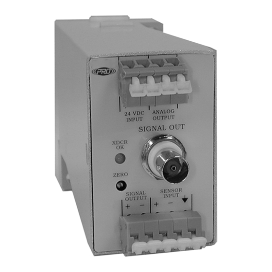
S E C T I O N I N S T A L L A T I O N Description The conditioner is housed in a plastic enclosure suitable for 35mm-din rail/surface mounting (Figure 2). On the front of the conditioner are electrical connectors (WAGO 237 series positive force terminal blocks) for the ±... -
Page 7: Mounting Instructions
S E C T I O N I N S T A L L A T I O N Mounting Instructions The conditioner case is designed for quick mounting to a 35mm din rail. The case can be surface mounted via optional mounting feet. 0.226 0.186 1.975... - Page 8 S E C T I O N I N S T A L L A T I O N Analog Output Zero Adjustment Figure 3 - Front Panel SIGNAL OUTPUT ± is an unfiltered connection showing the raw signal from the transducer.
-
Page 9: Section 3: Operation
S E C T I O N 3 : O P E R A T I O N Operating Procedure To operate the Signal conditioner, make sure that all wires are properly connected, then apply power. CAUTION: Make sure that power input does not exceed specified limits or damage to the system may result. -
Page 10: Section 4: Troubleshooting
S E C T I O N 4 : T R O U B L E S H O O T I N G Common Problems Blinking green sensor “OK light” indicates that sensor is not attached. Check sensor and cable connections. ... -
Page 11: Section 5: Maintenance
S E C T I O N M A I N T E N A N C E Maintenance Once the (product) has been installed, minimal maintenance will be required. Basic visual checks to ensure integrity should be made periodically. General There are no customer replaceable parts.
Need help?
Do you have a question about the Pro SC901 Series and is the answer not in the manual?
Questions and answers