Table of Contents
Advertisement
Quick Links
Advertisement
Table of Contents

Subscribe to Our Youtube Channel
Related Manuals for AstroNova TrojanLabel T3-OPX


Summary of Contents for AstroNova TrojanLabel T3-OPX
- Page 1 U S E R G U I D E...
- Page 2 T3-OPX User Guide Part Number 22834701-EN-E Revision 2.0 3/2021 TrojanLabel, An AstroNova™ Company Marielundvej 46A, 2. 2730 Herlev Denmark Phone +45 2964 0005 www.trojanlabel.com...
- Page 3 “us”) and is protected under Danish and Foreign copyright, trademark and other intellectual property laws. Trademarks Trojan™ is a trademark of AstroNova, Inc. Microsoft® Windows® XP, Windows® Vista, Windows® 7, Windows® 8, and Windows® 10 are registered trademarks of Microsoft Corporation.
- Page 4 Place of issue: West Warwick, RI European Contact: Your local AstroNova, Inc. Sales and Service Office. FRANCE - Parc Euclide, ZA la Clef de St Pierre, 10A Rue Blaise Pascal 78990 Elancourt, Tel: (+33) 1 34 82 09 00, Fax: (+33) 1 34 82 05 71 GERMANY - Waldstraße 70, D-63128 Dietzenbach, Tel.
-
Page 5: Table Of Contents
Contents Chapter 1: Introduction ........8 General Information . - Page 6 Contents Settings menu ........37 Statistics menu .
- Page 7 Contents Chapter 15: Specifications ........92 T3-OPX Specifications .
-
Page 8: Introduction
General Information Manufacturer The machine has been manufactured by: AstroNova, Inc. 600 East Greenwich Avenue West Warwick, RI 02893 USA The machine's designation The machine's complete designation is Digital Over-Printer type T3-OPX. -
Page 9: Overview And Application
Introduction Machine plate The machine plate is situated on the back side of the machine at the lower left corner: Overview and application General description The machine consists of a metal cabinet, ink delivery system, service door, print engine, embedded PC, touchscreen, media sensor, printhead, and four ink cartridges. If any changes or alterations are made to the machine, these changes or alterations must be reflected in these instructions as necessary. - Page 10 Introduction Front: Back: Touchscreen warnings Warning stickers and engravements on the back side of the touchscreen, indicating the depth of the VESA holes (5mm), that the screen can become hot on the back side, and the user should never open the cover of the screen, as this may only be serviced by an experienced and product trained technician.
-
Page 11: T3-Opx Physical Overview
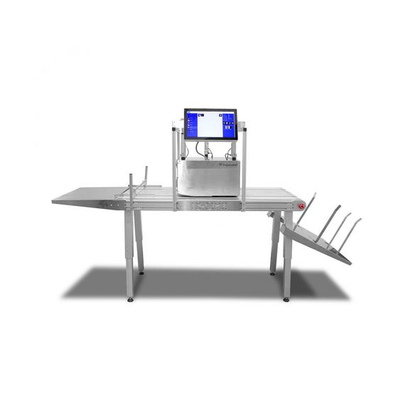
T3-OPX physical overview Front view Description Feeder table (optional) Media guides Vacuum unit (optional) Edge sensor Touchscreen Bracket Catch tray Table emergency stop Adjustable legs T3-OPX User Guide... -
Page 12: Back View
T3-OPX physical overview Back view Description Height controllers (three) Inlets Serial plate Ink lid T3-OPX User Guide... -
Page 13: Bottom View
T3-OPX physical overview Bottom view Description Pressure plate - Used to detect the media height. Crash plate - Protects the printhead. T3-OPX User Guide... -
Page 14: Media Entry Side (Feeder Side) View
T3-OPX physical overview Media entry side (feeder side) view Description Edge sensor Service door - Provides access to the print engine and service tray. Edge sensor reflective light emitter Knobs to move sensor T3-OPX User Guide... -
Page 15: Media Exit Side View
T3-OPX physical overview Media exit side view Description Aerosol filter (replaceable) Top lid - Provides access to electronic components. Front plate - Removable to access the printhead area. T3-OPX User Guide... -
Page 16: Connectors
T3-OPX physical overview Connectors Description IO serial port (e.g. for the feeder) Encoder serial port Table communications port Power inlet Network (Ethernet) USB port T3-OPX User Guide... -
Page 17: T3-Opx Installation
T3-OPX installation Installation overview This chapter describes how to install the T3-OPX using the standard bracket and height control actuators on one of the two TrojanLabel conveyor tables (MT1 or MT2). The operation of the mail tables is identical. Only the dimensions of the conveyor tables separates them. -
Page 18: Important Precautions
T3-OPX installation Important precautions Do not power on the unit before reading this document. Caution: The entry plate on the bottom of the T3-OPX printing unit is pressure sensitive. Do not drop the unit on any surface when moving it around before installation. The plate marked with green below is the pressure sensitive plate. -
Page 19: Mail Table Setup
T3-OPX installation Mail table setup The process is the same for mail table 1 and 2. Caution: This step requires heavy lifting, ensure lifting equipment or extra personal is present to move the table (Check local rules and regulations). Place the table upside down on a mat or similar surface to protect the belts. Mount the table feet. -
Page 20: Bracket System Installation
T3-OPX installation Bracket system installation Mount the side brackets on both table sides. Use four slot nuts from the middle. Leave at least one pair of slot nuts (upper and lower) on each side of the bracket. Center the brackets 400mm from the emergency stop button plate. Mount the bracket system on the conveyor table. - Page 21 T3-OPX installation Install the top bracket with four screws. Ensure the bracket pairs on each side are positioned relatively correct to the other pair. Carefully place the T3-OPX print unit on a box/surface that will raise the unit 25-35 mm under the bracket system.
- Page 22 T3-OPX installation Mount the screen. Install the screen on the bracket using the 4 screws. Install the cables on the PC (power, LVDS, mouse, and ground). On the touchscreen mouse connection, notice the red cable must align with the white triangle. Mount the actuators on the T3-OPX unit.
- Page 23 T3-OPX installation Notice the rotation of the actuator. The “motor” should be facing inwards and the hole at the bottom of the actuator should line up with the black plastic mount. Secure the actuator by pushing in the pin. Secure it with the pin on the end. Install the actuators onto the bracket system.
-
Page 24: Connect Encoder And Table Controls (Trojan Mt1 And Mt2)
T3-OPX installation Carefully remove the padding under the T3-OPX print unit. Ensure that the printer doesn't drop hard. Connect the actuator cables. It is important that they are connected as shown below. Mount the lid on the T3-OPX. Connect encoder and table controls (Trojan MT1 and MT2) This procedure requires the two serial cables included with the table. -
Page 25: Remove Service Tray Plastic Protectors
T3-OPX installation Remove service tray plastic protectors Remove the orange plastic protectors. These ensure the service tray does not shift position during transportation. Open the service door. Remove the two plastic protectors. Connect T3-OPX power supply cord and network cables This procedure requires the power supply cord (with grounding) and network cable. -
Page 26: Powering On
T3-OPX installation Powering on Safety check Before powering on the T3-OPX, visibly ensure that no foreign objects are interfering with the print engine module. Warning: Always use the supplied power supply cord connected to a grounded power outlet. Power on process Turn on the power via the power inlet switch on both T3-OPX and mail table (MT1/MT2). -
Page 27: Purging The Unit
T3-OPX installation Slide in the ink cartridge, nozzle end first, label side up. Push the cartridge in all the way. You will feel slight resistance near the end of this process as the nozzle engages the ink needles inside the printer. Repeat this step for each color. Close the ink door. - Page 28 T3-OPX installation • If using the TrojanMail table, ensure the print height controls have been initialized and the table position has been calibrated. See “Calibrate the table position and level the unit” on page 26. Open the service menu. Select Start purge on next power on. Confirm the process initiation.
-
Page 29: Calibrate The Printhead (Optional)
T3-OPX installation Success Purge process initialized successfully. Place spittoon under the printhead, then power off the printer unit by switching off the main PSU. Purge will automatically start on next power If the unit failed to move to the print height, check if the height control has been initialized in the handling menu. - Page 30 T3-OPX installation All parts require printing and scanning the result. The print unit will calibrate the nozzles and ink drop based on the scans. Below is an overview of the Diagnostics menu: Prerequisites • 1 x scanner (EPSON v600) • High grade ColorLok paper (Minimum A4), 160 grs (or heavier) •...
- Page 31 T3-OPX installation • If the print appears as shown below, press Go back to the diagnostics main menu. • If the print does not appear as shown, reprint the chart. Press Scan the nozzle alignment chart. Set Die-to-die overlap to 0. This feature is explained in “Printing on uneven surfaces (die-to-die overlap feature)”...
- Page 32 T3-OPX installation If successful, then apply the settings. Color density Open the Diagnostics menu. Press Print Density charts. Repeat the steps below for each color (CMYK). Place the paper on the table. Press Print density chart for C, M, Y or K color. Scan the result.
-
Page 33: Media Cleaner Installation (Vac)
T3-OPX installation Media cleaner installation (VAC) This section describes the process for installing the media cleaner (vacuum unit). Note: This procedure requires lifting of the vacuum unit during mounting. Ensure lifting equipment or extra personal is present (check local rules and regulations). Part number: 43162000 Description: VAC MEDIA CLEANER T3-OPX Power off the unit. - Page 34 T3-OPX installation Pull the cable through the back door hole and fix the grommet back into position using the same tool described above. Note that the cable connector should be inserted sideways through the hole. Make sure the cable is pulled over the cross bracket inside the print unit. Mount the cable in J17 on the T1030 board.
- Page 35 T3-OPX installation Mount the Vacuum unit onto the back door. The unit is mounted using the following supplied items: 8 screws (DIN7991-M4X8-A2) 8 bolts Washers (M4) 4 in each side Mount the screws from the inside of the back door, two at the bottom and two at the top, four on each side.
- Page 36 T3-OPX installation Insert the jack connector from the control cable (TC04058) and power cord. Close the back door and secure with the pre-mounted screws. Power on the unit. Update settings.ini. Under the meadiapath section, enable the vac unit by setting vacinst to 1. ;Enable Vacuum unit vacinst=1 Restart the unit.
-
Page 37: General Settings (Home Tab)
General settings (HOME tab) Overview menu Information from currently printed job, including: • Preview image of the label which is being printed at the moment • Label counter • Name of the print job in the Job Library Settings menu T3-OPX User Guide... - Page 38 General settings (HOME tab) • Service ID: A unique ID for each T3-OPX press. Based on the service ID, the Trojan- Label support team can access the Trojan Control remotely via the Internet and provide technical support. • Actual software version: Version number of the Trojan Control interface (GUI) currently running on the machine.
- Page 39 General settings (HOME tab) • Select Use DHCP checkbox to acquire IP address for the T3-OPX from the local network (as long as DHCP mode is selected, the T3-OPX ignores any static IP settings). • Current IP address field displays the current IP address of the T3-OPX on the local network.
- Page 40 General settings (HOME tab) • Use paging in job library: Enabled: Enables paging with finger swipe and with scroll bar in Job Library. Disabled: Disables swiping and scroll bar in Job Library. • Decimal separator: User can define separator for displaying decimals in the user interface.
- Page 41 General settings (HOME tab) create user accounts and can assign rights for each user to access certain func- tions in Trojan Control software. Icon Description Add new user Save new user settings / save changes in existing user account Delete user from list Important: The default password for the admin user is 123.
-
Page 42: Statistics Menu
General settings (HOME tab) • Default print queue state: Running: (Default) Print jobs are queued progressively as they are sent and processed in FIFO (first in first out) system. The queue can be managed from the Print queue menu. Paused: The print queue is paused when machine starts. •... - Page 43 General settings (HOME tab) • Cost/label (ink + PH) calculation is the cost/1 label in the actual print job based on ink tank price and printhead price given at HOME > Settings > Consumables menu. Print head cost is added. •...
-
Page 44: Shutdown
General settings (HOME tab) Shutdown • Shuts down the T3-OPX completely. When shutting down the unit it is advised to wait with turning the power switch off until the shutdown process is finished. There is a message on the display when the shutdown process is initiated to indicate that the shutdown process is still going on. - Page 45 General settings (HOME tab) • Type the actual IP address of the T3-OPX into a browser at a user PC: • Press Export to CSV button on page to save the statistics into a CSV file. Note: Ink consumption is more detailed in this view and displayed for each used base color (CMYK) and in total as well.
-
Page 46: Transferring Print Jobs To The T3-Opx Using The Xitron Rip
Transferring print jobs to the T3-OPX using the Xitron RIP Starting the Xitron RIP server To transfer jobs using the Xitron RIP it is required that the RIP server is running. Note the server does not have to run on the same PC as the client. This can be done two ways on the RIP server PC: Click the Windows start menu, open Navigator, then click Navigator Server. - Page 47 Transferring print jobs to the T3-OPX using the Xitron RIP Navigate to your file in the pop-up window. Select your file, then select the OPEN button. After the file is uploaded the QUICK EDITS screen is opened. In this screen you can make various changes such as rotations, print range, collation, etc.
- Page 48 Transferring print jobs to the T3-OPX using the Xitron RIP In the Full Job Editor screen you can do the same changes as the QUICK JOB EDITOR as well as changing the Paper Profile, Overall Color Changes and Spot Color Adjustments.
- Page 49 Transferring print jobs to the T3-OPX using the Xitron RIP Media size To use the offsetting (moving) and rotation, it is important that the Media size is adjusted to fit the new dimensions. When a job is loaded the media size will automatically be set the dimension of the job, including any white space.
- Page 50 Transferring print jobs to the T3-OPX using the Xitron RIP Offsetting A print job is per definition centered, so you need to move the artwork using the offset buttons and adjusting the “media size” to fit it differently. Alternatively align the media differently. Use the buttons to offset the artwork, the units (inches or mm) are decided by the locale of the PC.
- Page 51 Transferring print jobs to the T3-OPX using the Xitron RIP Click + button and give the Media size a new name. Open the DFE in the browser again Select the new Media in the size drop down. T3-OPX User Guide...
-
Page 52: Printing A Job From The Job Library
Printing a job from the Job Library The two most common menus that the operator will use when printing jobs: Job Library and Media Settings. See “Media settings overview” on page 62. Description Feeding side Print unit Exit side Note: All jobs are centered by default. Use the RIP to move the print or position the media accordingly. - Page 53 Printing a job from the Job Library Enter the number of units to print, by clicking the units button. Press the green print button. Feed the media. T3-OPX User Guide...
-
Page 54: Operation Menus
Operation menus General counter The general counter is an accumulative counter that counts each page printed for all jobs printed, until it is reset by pressing the circular button. The counter is also reset when the unit is turned off. It is not reset, if the screen goes into sleep mode. Enable/Disable the general counter To Enable/Disable the general counter, go to the HOME tab and select Settings >... -
Page 55: Handling Overview
Operation menus Handling overview The Handling menu is used for moving the print unit up or down, moving the mail table and adjusting/testing the vacuum fans when printing. Initialize height control Press the button for the unit to initialize the height controllers. When the unit is powered on the initial Media Path State status will be “Uncalibrated”... - Page 56 Operation menus Fan control (MT1 and MT2 controls) Icon Description Use the start button to test the fans. Use the stop button to stop the fans. Use the Zone (1-5) controls to individually set the fan speed from 0 to 100. Physical emergency stop button The emergency stop placement on the mail table: Pressing the emergency stop button will:...
-
Page 57: Maintenance Overview
Operation menus Maintenance overview The maintenance menu controls the printhead maintenance functions, which include cleaning, replacing the service tray, testing print position, and printhead capping. Light Clean The Light Clean option will make a quick wipe of the printhead and activate the nozzles by spitting. - Page 58 Operation menus If the Vacuum unit is installed, this can be left on, as the gas dampers can hold the weight of the VAC unit. Press the Remove service tray button and wait for the service tray to retract. Pull out the service tray and replace it with a fresh tray.
-
Page 59: Job Library
Operation menus Job Library The Job library is where the jobs sent from the RIP are placed. The jobs are named by the RIP, which typically is the pdf filename. The job library size is limited to space of the hard drive (SSD) of the unit, typically 25-50 GB. - Page 60 Operation menus Icon Description Number of copies. Note that if the job is a multi-page job then this is the number of copies of the multi-page job. For example, if the job contains 1000 pages, then this example will produce 5 x 1000 pages. Print from a certain page number (ONLY works for multi-page jobs).
- Page 61 Operation menus Information display Icon Description Cost/label calculation button. Pressing this button will print the job and calculate the pure ink consumption and cost. The ink cost is based on the cartridge pricing set in HOME > Settings > Consumables menu and the estimated ink consumption for 1 print.
-
Page 62: Print Queue
Operation menus Print queue Print jobs are queued progressively as they are sent and processed in a FIFO (first in first out) system. The queue can be managed from the Print queue menu. The currently printed job in the queue cannot be deleted, this must be stopped from the Overview Menu. - Page 63 Operation menus The Media settings has a profile control section and three tabs to manage the properties of the selected profile. Profile control section Media profiles are the base of a print job. The media profile is the configuration of either a print job or/and the media being printed on, such as pre-setting the height of the media and where the artwork is positioned on the media.
- Page 64 Operation menus Select a profile Select a media profile from the drop-down list. Delete the selected profile Deletes the media profile, when confirming the deletion pop up. Basic tab This is where the typical settings are managed. TOF offset (mm): Set the distance from the edge of the material (registered by the edge sensor) to the posi- tion of the printed artwork.
- Page 65 Operation menus • Move and adjust height button Moves the media placed on the conveyor belts on the entry side under the pressure plate, then starts the automatic height adjustment. When complete the media will be moved back to the starting position. Requirement: The entry sensor must be able to register the media.
- Page 66 Operation menus Fans tab The general setting of the mail table vacuum fans are managed in the Handling menu, however these settings can be overridden by checking the Use custom settings box. The start, stop, and zone controls are not visible until the Use custom settings box is checked. When it is checked use the start and stop button to test the fan settings in Zone 1-5.
-
Page 67: Automatically Calibrating The Job/Media Height
Automatically calibrating the job/media height The T3-OPX can automatically adjust the height controllers to the media that the operator wants to print on. The height can then be saved to a media profile. Using the fully automated height adjustment process Select the media to print on. - Page 68 Automatically calibrating the job/media height Additional information The Height Controllers will move up to 20mm when pressing the Move and Adjust Height button if the current print height is physically less than 20mm. Setting the force too high can crush the material. If the edge sensor does not detect the material, then the belt will stop and return the media and display an error “Auto print height adjust error: product not found”.
-
Page 69: Printing On Uneven Surfaces (Die-To-Die Overlap Feature)
Printing on uneven surfaces (die-to-die overlap feature) When printing on uneven surfaces it can be useful to use the die-to-die overlap feature. This feature will enable to the operator to move the print unit further from the media. We recommend only doing this using an existing successful scan of the nozzle alignment plot. This is indicated with the button “Use last successful scan”... -
Page 70: Individual Die-To-Die Alignment
Printing on uneven surfaces (die-to-die overlap feature) Select Apply nozzle alignment settings. The process is complete. Remember to insert the value of 0 when restoring the alignment. Note: The functionality involves updating the actual nozzle alignment within the printhead. This means that the feature requires a recalibration of the nozzle alignment every time and is therefore not a part of the Media Profile (in media settings). - Page 71 Printing on uneven surfaces (die-to-die overlap feature) Evaluate the chart. The printed chart displays a number for each overlap. Apply the settings by checking the Use individual die-to-die overlap setting (Diagnostics > Scan Nozzle Alignment Plot. T3-OPX User Guide...
- Page 72 Printing on uneven surfaces (die-to-die overlap feature) Adjust the values individually. Examples below show the effect of using the extreme values: T3-OPX User Guide...
-
Page 73: Remove The Die-To-Die Alignment
Printing on uneven surfaces (die-to-die overlap feature) Apply the settings using the Use the last successful scan button. Print the chart again or test an actual print job with the new settings. Remove the die-to-die alignment Set the general or all individual values to zero and press Use the last successful scan button. T3-OPX User Guide... -
Page 74: Edge Sensor (Tof Control)
Edge sensor (TOF control) The edge sensor is used to detect the edge of the material moving under the print unit. The edge sensor can be moved by twisting the knobs on each side of the rod. The sensor can be moved across the width of the print unit, but DO NOT place the sensor over a belt, as this will interfere with the edge registrations. -
Page 75: Adjusting The Sensor To The Media
Edge sensor (TOF control) Description step pushbutton > (manual switching threshold: higher/next function parameter) step pushbutton < (manual switching threshold: lower/previous function parameter) Mode/Enter-button Teach-in button Adjusting the sensor to the media Move the print unit to a height position where the media can pass underneath. It does not need to 100% set to the height but within 10mm above the media. -
Page 76: User Replaceable Parts
User replaceable parts This chapter describes all parts that can replaced by the operator excluding ink cartridge replacement which is explained earlier. See “Installing ink cartridges” on page 26. Ink cartridge part numbers Part number Description 27610001 High Yield Cyan Ink Cartridge (~16,000 pages) 27610002 High Yield Magenta Ink Cartridge (~16,000 pages) 27610003... - Page 77 User replaceable parts Service tray replacement process Unpack the new service tray. Ensure the unit is not printing. Go to the T3-OPX tab. Select Maintenance. Press Remove Service Tray. Open the service door on the feeding side of the unit by removing the four finger screws. Leave the optional Vacuum unit on.
- Page 78 User replaceable parts Lift up the service door until it stops. The gas pumps will maintain the position. It can carry the weight of the optional Vacuum unit. Wait for the service tray to be pushed to the end. Pull the service tray out. Install the service tray by pressing it back into position of the edge of the print module.
-
Page 79: Fuse Power Inlet Replacement
User replaceable parts Insert the Torx screwdriver and locate the service tray screw (should be straight in). Warning: Moving the service tray will uncap the printhead. Be careful with this operation. Fuse power inlet replacement The fuse in the power inlet can be replaced by the operator. Part Number Description 15140120... -
Page 80: Aerosol Filter Replacement
User replaceable parts Insert the replacement fuse. Aerosol filter replacement The aerosol filter absorbs fine ink particles that are not absorbed by the media when printing. Although the filter is effective, some particles will still end up in the print zone, on the printhead, table and side walls. -
Page 81: Rip Installation (Xitron)
RIP installation (XITRON) Software requirements and recommendations Minimum requirements • Windows 10 Professional 64-bit • 250+ GB Hard drive • 3 GHz Dual/Quad Core Processor Core i5 or i7 recommended • 8 GB RAM • 100/1000 Ethernet Network Interface Additional information •... -
Page 82: Installation Process
RIP installation (XITRON) Installation process Plug in the USB dongle. A 36-digit code is delivered with the dongle. Please uninstall existing copies before installing this version. Download the latest version of the RIP from the website. (http://trojanextranet.com/External/RIP/NavigatorT3OPX.zip) Be sure to unzip the entire folder before running the installer. Install both the RIP server and client on the PC by double clicking the Navigato- rHHRInstaller.exe file. -
Page 83: Link Trojancontrol
RIP installation (XITRON) Link TrojanControl Insert the IP address of the RIP server in the TrojanControl. This will enable features: • Show thumbnails in the Job Library • Enable the RIP client tab Go to HOME > Settings > Network. Click on the Xitron tab. -
Page 84: Debugging Connections
Debugging connections To debug the webpath board connect an external PC to the T1030 board (the new webpath). Use a USB to USB Mini cable to connect. To connect an external PC to the MPCA. Use a USB AB cable to connect. Controls for T1030 (webpath board) These commands can be run through the webpath, accessed through putty, or directly through teraterm (USB mini connection):... - Page 85 Debugging connections Function Command Comment Calibrate the table position calall height and x/y tilt, to create the base settings. Read the power state of the It will return 1 if the power is Mpcap mpca Push the virtual power 2 the button is pressed, 0 Mpcap (2 or 0) button of the MPCA the button is released.
-
Page 86: Physical Data
Physical Data MT1 Illustrations Top View Dimensions T3-OPX User Guide... - Page 87 Physical Data Front View Dimensions T3-OPX User Guide...
- Page 88 Physical Data Isometric View SHOWN WITH OPTIONAL ACCESSORIES • 10000234, STANDARD CATCH TRAY • 10000233, STANDARD INFEED TABLE • 43162000, VAC MEDIA CLEANER T3-OPX T3-OPX User Guide...
-
Page 89: Mt2 Illustrations
Physical Data MT2 Illustrations Top View Dimensions T3-OPX User Guide... - Page 90 Physical Data Front View Dimensions T3-OPX User Guide...
- Page 91 Physical Data Isometric View SHOWN WITH OPTIONAL ACCESSORIES • 10000236, CATCH TRAY FOR MT2 • 10000235, EXTENSION TABLE FOR MT2 • 43162000, VAC MEDIA CLEANER T3-OPX T3-OPX User Guide...
-
Page 92: Chapter 15: Specifications
Specifications T3-OPX Specifications Operation Ink Type Pigmented ink, 4 Individual CMYK cartridges Resolution High Resolution Mode: 1200 x 1200 optimized dpi from 600 x 600 input dpi. Production Mode: 600 x 1200 optimized dpi from 300 x 300 input dpi. Print speed Up to 18 ips (27m/min) Print Area... - Page 93 Specifications Environmental & Physical Media cleaning unit weight 3.5 kg Drop detection Print then scan process, using offline scanner (Epson v600). Supplies Ink Cartridges CMYK pigmented: C: 238 ml M: 233 ml Y: 225 ml K: 498 ml ISO pages: K: 20.000 pages CMY: 16.000 pages Maintenance...
-
Page 94: Resolution
Specifications System Software TrojanControl Software RIP Server Software requirement Windows 10, 8 or 7 (64-bit) RIP Client Software requirement Chrome browser (Mac OS or Windows) Resolution The pen (printhead) native resolution is 1200dpi, so all images are scaled up to 1200dpi after halftoning in the pipeline. -
Page 95: Mailtable 1 (Mt1) Specifications
Specifications MailTable 1 (MT1) Specifications MailTable 1 Standard Speed Up to 18 ips (27m/min) Power requirements 100-240V AC - 50/60 Hz (2.5A power supply) Dimensions Width: 626 mm (incl Emergency stop button) Length: 1507 mm Height: From 892 mm to 595 mm Support material width 600 mm Weight... -
Page 96: Mailtable 2 (Mt2) Specifications
Specifications MailTable 2 (MT2) Specifications MailTable 1 Wide Speed Up to 18 ips (27m/min) Power requirements 100-240V AC - 50/60 Hz (2.5A power supply) Dimensions Width: 1026 mm (incl Emergency stop) Length: 2007 mm Height: From 890 mm to 590 mm (5 positions) Support material width 1000 mm... -
Page 97: Index
Index Application ....... . 9 Handling menu ......55 Height calibration . - Page 98 Index Service ID ....... . 38 Service tray protectors ..... . 25 Operation menu .
Need help?
Do you have a question about the TrojanLabel T3-OPX and is the answer not in the manual?
Questions and answers