Table of Contents
Advertisement
Quick Links
Advertisement
Table of Contents

Subscribe to Our Youtube Channel
Related Manuals for Harman AMX VPX-1401

Summary of Contents for Harman AMX VPX-1401
-
Page 4: Table Of Contents
Table of Contents IMPORTANT SAFETY INSTRUCTIONS ................2 Overview ........................6 Features........................6 Package Contents ....................6 Specifications ......................7 Transmission Distance ..................9 Panel Description ....................10 Front Panel Description .................. 10 Rear Panel Description ................... 15 Pinout Information ......................15 RS232&IR ...................... - Page 5 Logo ......................27 Network ......................28 System......................29 Firmware Upgrade ......................32 Before Starting ...................... 32 Transferring KIT Files..................... 32 Troubleshooting ......................34 API Command Set ......................35 NetLinx Commands ....................35 Telnet/SSH Commands ................... 44 User Manual – VPX-1401...
-
Page 6: Overview
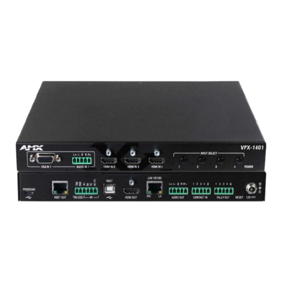
Overview VPX-1401 is an advanced presentation switcher, allowing switching among four inputs and distribution to two outputs. It offers one VGA input with one balanced analog audio embedded, three HDMI inputs, one HDMI output to a local display, plus one balanced de-embedded analog audio output and one HDBaseT mirrored output to a remote display via a Cat X cable. -
Page 12: Pinout Information
Pinout Information The following figures show the pinouts of the phoenix connectors. RS232&IR Connects to the RS232 and IR devices with the 6-pole, 3.5mm captive screw connectors. Audio IN/OUT Connect to audio device with the 3-pole, 3.5mm captive screw connector. User Manual - VPX-1401... -
Page 13: Installation And Wiring
Installation and Wiring Warning: Before installation, ensure the device is disconnected from the power source. Installation Attach the installation bracket to the enclosure using the four screws provided. The bracket is attached to the enclosure as shown. Repeat steps 1-2 for the other side of the unit. Attach the brackets to a surface or suitable location with user supplied screws. -
Page 15: Osd
The VPX-1401 supports OSD (On Screen Display) to display its IP address. Follow these steps to initiate OSD: Press and Hold the front panel buttons Input 1 and Input 2 for at least 3 seconds. The IP address of the VPX-1401 will display at the upper right of the connected display’s screen for about 15s and then disappear. -
Page 16: Input Source Switching
Input Source Switching VPX-1401 supports Auto and Manual Switching among the VGA and HDMI inputs. Auto Switching When multiple sources are inserted, and power is ON for all devices, the input will be switched to the active source with the highest priority. Priority: VGA IN 1 >... -
Page 19: Netlinx Control
NetLinx Control Controlling the VPX-1401 through NetLinx Studio. Before launching NetLinx Studio, connect the VPX-1401, PC, control system (e.g. NX-3200) to the same network. Note: IDs and IP addresses in the following illustrations are examples. Check the Online Tree in NetLinx Studio to find the correct addresses for your device. -
Page 20: Send Command To Control A Device
Send command to control a device Click “Diagnostics” on the menu bar, select “Control a Device”. A window will display as follows, type the Device number, Port number, System and command respectively, and click “Send To Device”. (For API commands, see the Section API Command Set.) Telnet Control Launch Telnet Window To launch Telnet Window,... - Page 21 The Telnet window opens. At the prompt (>), type the Telnet command and press Enter. * Selecting “Launch TELENT Window via User Defined Program”, may require enabling Telnet by completing the following: (1) go to Start/Control Panel/Programs and Features; (2) on the left, select “Turn Windows features on or off”; (3) select the check-boxes Telnet Client and Telnet Server, and click OK.
-
Page 22: Web Ui Control
Web UI Control To configure and control the device on the Web, right click the Device Number in the Online Tree Tab, choose “Web Control Page” – “Launch Web Control Page via NetLinx Studio”. User Manual – VPX-1401... -
Page 23: Web Ui Control
Web UI Control The Web UI designed for the VPX-1401 allows basic controls and advanced settings of the device. The Web UI page can be accessed through NetLinx Studio. To access the VPX-1401 Web UI: Connect your PC and the LAN port of the VPX-1401 to the same local area network. In NetLinx Studio’s Online Tree, select “Web Control Page”... -
Page 24: Navigation Bar
A successful reset will restore all the device settings to their factory defaults and the device will reboot automatically. Allow at least 2 minutes for the reboot to complete. : Reboot button, click to reboot the device. Steps to reboot the device: Click “Reboot”... -
Page 25: Key Lock
Key Lock Key Lock allows locking of the buttons on the VPX-1401 to prevent accidental or unwanted switching. • ON: Click to enable Key Lock. • OFF: Click to disable Key Lock (default setting). HDCP HDCP Support allows enabling or disabling HDCP compatibility of each input and HDMI output. •... -
Page 26: Display
Display Auto Display Control allows control of CEC-enabled displays connected to the VPX-1401 through HDMI. • ON: Click to enable the Auto Display Control. • OFF: Click to disable the Auto Display Control. (Default setting) • DELAY TIME (1~30 min): Click the down arrow to set the time for the display to power off automatically when no signal is present. -
Page 27: Logo
• MANUAL: Click to set the output resolution to Manual mode. In Manual mode, click the down arrow to select a specific output resolution as required. • APPLY: Click to set the output resolution to the desired setting. Logo Logo section allows display content configuration for the display screen when there’s no signal output to the display. -
Page 28: Network
Network Device IP Mode: • DHCP: When enabled, the IP address of the switcher will be assigned automatically by the connected DHCP server. • Static: When the switcher fails to obtain or detect an IP address from the network to which it is connected, select “Static” to set up the IP address manually. -
Page 29: System
System The system section is used to configure the ICSP Parameter, login password, Telnet/SSH account and upload certificate. ICSP PARAMETER: • CONNECTION MODE: includes four options: NDP, Auto IP, URL/TCP, URL/UDP. The default setting is NDP. • CONTROLLER URL: Input the connected controller’s URL. SYSTEM NUMBER: Use the Online Tree to determine the system number. - Page 30 • Upload: Click to upload the https certificate and its private key to the device. Note: When certificate upload is completed, the certificate module will reboot automatically. User Manual – VPX-1401...
-
Page 31: Firmware Upgrade
Firmware Upgrade The VPX-1401 uses KIT files for firmware upgrade. Before Starting Verify that you have the latest version of NetLinx Studio on your PC. Download the latest firmware (KIT) file to your PC. (Place KIT files on a local drive for the fastest throughput.) Verify the following: a) Verify that an Ethernet/RJ-45 cable is connected from the VPX-1401 to the same network as the control system. - Page 32 Check the number of the Device to be upgraded in the Device text box. • The device number is 32002. • The system number is 3. (Use the Online Tree to determine the system number.) Click “Send” to upgrade the firmware. Click the button on Web UI page to check the upgrade status.
-
Page 33: Troubleshooting
Troubleshooting Power: Ensure all devices are powered on. Indicator: Ensure all LED indicators of the switcher are normal according to the user manual. Devices: Ensure picture can be shown normally when directly connecting a source a display device. Cable: Plug the HDMI/Cat X cable in and out or connect a different HDMI/Cat X cable. Ensure the specific cable length is within the available transmission range according to the Specifications Section. - Page 54 About AMX by HARMAN Founded in 1982 and acquired by HARMAN in 2014, AMX® is dedicated to providing AV solutions for an IT World. AMX solves the complexity of managing technology with reliable, consistent and scalable systems comprising control, video switching and distribution, digital signage and technology management. AMX systems are deployed worldwide in conference rooms, classrooms, network operation/command centers, homes, hotels, entertainment venues and broadcast facilities, among others.
Need help?
Do you have a question about the AMX VPX-1401 and is the answer not in the manual?
Questions and answers