Table of Contents
Advertisement
Quick Links
ENGINE
GROUP 6
Section
Engine
6 A
Mechanical and Mounts
All Models
Cooling System
6B
All Models . . . . . . . . . . . . . . . . . . . . . .
Fuel System
6C
All Models . . . . . . . . . . . . . . . . . . . . . . . .
Exhaust Systems
6D
All Models . . . . . . . . . . . . . . . . . . . . . . . .
Carburetor
6E
And
Throttle Linkage . . . . . . . . . . . . . .
Emission Control
6F
Systems - All Models . . . . .
Tune-Up
6G
All Models . . . . . . . . . . . . . . . . ..__....
Title
'age No.
Advertisement
Chapters
Table of Contents

Summary of Contents for Opel 1973
- Page 1 GROUP 6 Section Title ‘age No. Engine Mechanical and Mounts All Models Cooling System All Models ..... . ENGINE Fuel System All Models .
- Page 2 The head surface is alumetized and so are the seats of the The 1.9 liter engine is standard equipment on all 1973 Opel 1900, Manta and GT models. This engine has non- scaling and promotes long life. All engines have a compression ratio of 7.6:1 and operates...
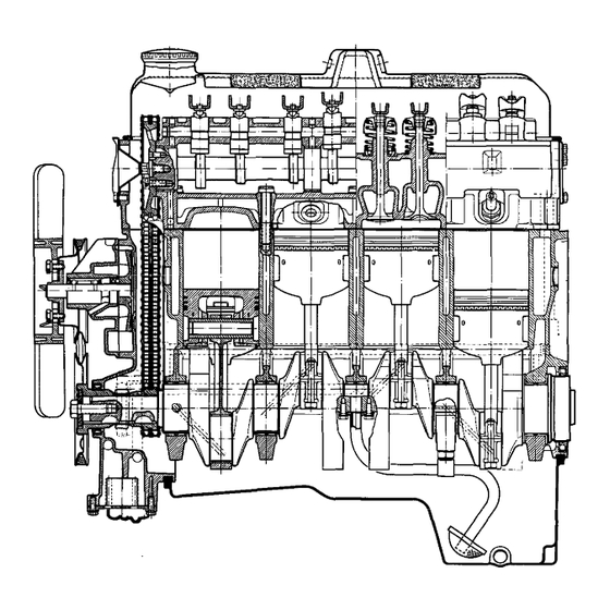
- Page 3 ENGINE MECHANICAL AND MOUNTS Figure 6A-1 Side Cross Section View of Engine This engine has full skirt “Autothermic” type pistons the camshaft front bearing seat outer face in one with two horizontal slots in oil control ring groove, direction, and by the front bearing cover in the other which partly separate head and skirt to maintain direction.
- Page 4 1973 OPEL SERVICE MANUAL Hot exhaust gases are used for heating a vaporization hand side above crankshaft sprocket, has a plunger plate located at bend of intake manifold below carbu- head with oil- proof and wear-resistant synthetic retor and communicating with its tinned underside...
- Page 5 ENGINE MECHANICAL AND MOUNTS incorporating a gear-type pump driven by the dis- and pumps it through drilled passages in timing case tributor shaft. The pump body forms part of the to the full flow filter. From there it passes to the timing case.
- Page 6 1973 OPEL SERVICE MANUAL DIAGNOSIS EXCESSIVE OIL CONSUMPTION C o n d i t i o n C o r r e c t i o n Tighten attaching bolts. If leaks External Oil Leaks at: Rocker Arm Covers persist, remove cover (or pan),...
- Page 7 ENGINE MECHANICAL AND MOUNTS engine off. It makes no difference whether the engine Pour penetrating oil over the valve spring cap and is cold or is at operating temperature. Set piston of allow it to drain down the valve stem. Apply pressure the respective cylinder to upper top center on the to the one side of the valve spring and then the other, and then rotate the valve spring about l/2 turn.
- Page 8 ASSEMBLY REMOVAL INSTALLATION Removal (Opel 1900 and Manta)’ The engine assembly on the Opel 1900 and Manta can be removed together with the transmission through the top of the engine compartment. 1. Remove hood (scribe hood hinge to hood mount- Figure 6A-7 Transmission Support Bolts .
- Page 9 ENGINE MECHANICAL AND MOUNTS The engine does not rest on the front suspension cross member as in the Opel 1900 and Manta but on a separate cross member. On removal and installa- tion of the engine the front suspension cross member need not be detached.
- Page 10 1. Lower engine and transmissior assembly into car. device was made up using hardwood, bolts, and chain. 2. Install components as remov&d in steps .1 through 1. Assemble chains to engine. 19 above. Figure 6A-14 Engine Support Tool - Opel 1900 and Manta.
- Page 11 10. Lower the front suspension assembly and remove from under car. 11. Drain engine oil and remove oil pan and gasket. Installation (Opel 1900 and Manta) Figure 6A-15 Engine Holding Fixture 1. Apply a light bead of sealer to the clean sealing surfaces of the oil pan and affix a new gasket.
- Page 12 1973 OPEL SERVICE MANUAL 4. Connect parts removed in Steps 1 thru 8 above. INTAKE AND EXHAUST MANIFOLD REMOVAL A N D CYLINDER HEAD REMOVAL AND INSTALLATION INSTALLATION R e m o v a l R e m o v a l 1.
- Page 13 ENGINE MECHANICAL AND MOUNTS Apply silastic sealer or equivalent to both sides of the cylinder head gasket where the gasket mates with the timing chain cover, place new cylinder head gas- ket onto cylinder block. 5. Install cylinder head. Be careful to place head squarely over guide pins.
- Page 14 1973 OPEL SERVICE MANUAL 5. Clean carbon and gum deposits from valve guide wire brushes for removing carbon, avoid scratching bores. valve seats and valve faces. A soft wire brush such as J-8089 is suitable for this purpose. 6. Inspect valve faces and seats for pits, burned spots or other evidences of poor seating.
- Page 15 ENGINE MECHANICAL AND MOUNTS New inlet valves must not be refaced or lapped with 10. Install cylinder head. grinding compound. The correct angle for the intake and exhaust valve head is 44 degrees. 11. Adjust valve clearance. See MAINTENANCE ADJUSTMENTS. 7.
- Page 16 1973 OPEL SERVICE MANUAL lengthwise along the bottom center of the lower bear- Inspection of Connecting Rod Bearings and ing shell (Figure 6A-25, view A), then install cap Crankshaft Journals with shell and tighten nuts to 36 lb. ft. Do not turn crankshaft with gauge type material in bearing.
- Page 17 ENGINE MECHANICAL AND MOUNTS The ends of she//s bearing noise, it is not necessary to replace the bear- seating and to prevent turning. must never be tiled flush with parting surface of ing. bearing cap. crankcase or 6. Loosen all crankshaft bearing cap bolts l/2 turn, and remove cap of bearing to be replaced.
- Page 18 1973 OPEL SERVICE MANUAL pressure. If heavy pressure is required, shell was not 2. Remove flywheel. started squarely and will be distorted if force into place. 3. Punch a hole into oil seal and screw in a sheet metal screw and pull out oil seal. See Figure 6A-28.
- Page 19 ENGINE MECHANICAL AND MOUNTS 8. Remove other rod and piston assemblies in the torque to 43 lb.ft. same manner. 9. Remove compression rings and oil rings. PISTON, RINGS AND CONNECTING RODS 10. Remove piston pin in following manner: Removal and Disassembly of Piston and Rod Assemblies a.
- Page 20 6A. 20 1973 OPEL SERVICE MANUAL diameter at the right angle to the piston pin is greater Cylinder bores may not be the same size. Standard than the diameter parallel to the piston pin. When a replacement piston sizes are in the midpoint of the piston is checked for size, it must be measured with cylinder bore size range.
- Page 21 ENGINE MECHANICAL AND MOUNTS 2.. Expand a telescope gage to fit the cylinder bore at cylinders, the glazed cylinder walls should be slightly right angles to the piston pin 2-l/2” from top. See dulled without increasing the bore diameter by Figure 6A-33.
- Page 22 1973 OPEL SERVICE MANUAL b. Place tool J-23436-l in support J-6047 with small diameter bore facing upward. J-23436- 1. d. Position piston, rod, and pin guide J-23436-3. e. Line up pin on piston, and using tool J-23436-4 press pin into piston. See Figure 6A-37.
- Page 23 Then install rubber strips in grooves in rear main bearing cap and engine front cover. Install oil pan, torquing bolts to 5 lb.ft. 14. Install (Opel 1900 and Manta) front suspension assembly. (GT) Install engine suspension cross mem- Figure 6A-39 Bolt Behind Water Pump ber.
- Page 24 1973 OPEL SERVICE: MANUAL 5. Inspect chain tensioner for proper operation and on front side of timing chain to permit reinstallation reusability. in original position. 6. Install timing case rubber gaskets to cylinder Timing Chain Cover and Timing block. Stick on with grease as necessary. Gaskets will Chain installation somewhat overlap with oil pan gasket.
- Page 25 ENGINE MECHANICAL AND MOUNTS Figure Installing Timing Chain Cover Oil Seal Replacing Distributor Drive Gear 1. Remove fan belt. 2. Remove fuel pump. Plug end of fuel line with a suitable stop. 3. Remove spark plug wires, distributor hold down clamp.
- Page 26 1973 OPEL SERVICE MANUAL rear of cylinder head. Remove camshaft toward front, supporting camshaft with one hand through access hole and taking care not to damage bearing surfaces. See Figure 6A-43. 4 . C O V E R G A S K E T R E L I E F 5 .
- Page 27 E N G I N E M E C H A N I C A L A N D M O U N T S With feeler gauge, check gear backlash. It should be 3. Remove (2) bolts holding pipe and screen assem- between .I?04 in.
- Page 28 1973 OPEL SERVICE MANUAL Torque Part Lb.Ft. Connecting R o d Bolts ............Crankshaft Main Bearing Bolts .......... Flywheel t o Crankshaft Attaching Bolts ......Cylinder Head Attaching Bolts ..Cold 72 -Warm 58 Camshaft Sprocket Attaching Bolts ........ Generator Bracket to Cylinder Block Attaching Bolts ..............
- Page 29 ENGINE MECHANICAL AND MOUNTS Cooling System - Type ,._...___..___..___......Liquid Cooling With Circulating Pump Filler Cap Type - Pressure _,._.,,._.,,...,,..,..,..,.,....,,......13.2-15.2 PSI Water Temperature Control ._,..__,,._.,,__.,,...,.,.,,.,,.,,.,....,,...,,,... Thermostat and Bypass Thermostat Open At ._,,.,,..,__.,..,,...,...,,..,.,,.,,............189 F. 6 Qts. Cooling System Capacity ...._...__....,,.,,.,,..,........,,....Fan Drive .,,...,,,..,,.,..,..,,..,..,,..,,,.....,..,,.,..,,....,,....
- Page 30 SERVICE MANUAL Valve Seat and Correction Angle in Cylinder Head Intake 45” Correction .,,,.,,._.,._..___,,,.,,,,,..,,.,..,...,,..,..,,..,,..,,,..........30” Exhaust Valve Seat Angle ,,,.,,.__,.__..___.,..,,..,...,,..,..,..,..,,..,..,...,..,,,...,,......... 45” Outer Correction .,,..,,...,._.,.__..,,,..,,,................30” Valve Face Angle ,,..,,,..,.__..__.._..,,,..,,...,,..,.,..,..,..,,.,,,..,..,,,..,,,..,,,...,,........ Valve Seat Width in Cylinder Head Intake ...._..._._....,,..,..,,..,....,...,..,,,..,,..,,...,,...,,,..,....Exhaust .,..,,,..,,.___..,,..,,...,..,,,..,,...,,...,,....,,..,,..,,..,,...,.....
- Page 31 ENGINE MECHANICAL AND MOUNTS...
- Page 32 1973 OPEL SERVICE MANUAL COOLING SYSTEM CONTENTS Page No. Subject DESCRIPTION AND OPERATION: Cooling System and Water Pump ....... .
- Page 33 COOLING SYSTEM remove drain plug on right.side of cylinder block. Set indicate that it meets General Motors Specification GM 1894-M. It should be recognized that this is only heater temperature control valve at full heat posi- tion. After the cooling system is drained, and plugs a temporary measure.
- Page 34 3. Remove lower attaching and slide radiator upward and out of engine compartment. Water Pump Removal Opel radiators do not have a drain plug. Drain radia- Installation tor by first, loosening radiator cap, then remove lower hose from lower radiator tank.
- Page 35 COOLING SYSTEM SPECIFICATIONS 1973 COOLING SYSTEM CAPACITIES Liquid Cooling With Circulating Pump Cooling System - Type ............. 13.2-15.2 PSI Filler Cap Type - Pressure _.._..__.._.._.,,.,,..,,.,,..,.,,..,,,.,,,..,...
-
Page 36: Table Of Contents
1973 OPEL SERVICE MANUAL FUEL SYSTEM ALL MODELS CONTENTS Page No. Subject DESCRIPTION AND OPERATION: Fuel Pump ................ -
Page 37: Evaporation Control System
An AC fuel filter type (GF 423) is being used on all tainer. 1973 Opels. A vapor return line returns vapors in the fuel line back to the fuel tank. Proper installation of 3. A small tube above the throttle valve body con- the filter is essential. -
Page 38: Evaporation Control System
(a) Strainer must be properly seated with projections facing upward. tions, more frequent attention may be required. Figure W-4 Exploded View of Opel 1900 and Manta Fuel Tank... -
Page 39: Major Repair
FUEL SYSTEM MAJOR REPAIR FUEL TANK OPEL 1900 AND MANTA The fuel tank is located below the luggage compart- ment floor panel and is attached with a strap. The plastic tank vent hoses join in a connector from where the fuel vapors escape through a fourth ho% attached to the upper flange of the tank. - Page 40 1973 OPEL SERVICE MANUAL 6. Remove spare tire support attaching brackets. Spare tire hold-down and support attaching brackets are ;attached to the rear wheel house panel and are Figure 6C-1 1 Tank Vent and Filler Hoses Attachment at Figure Fuel Line...
- Page 41 3. Remove fuel gauge tank unit, together with suc- tion tube and screen. Clean screen and blow out from 6. Connect battery. cover side. Flush fuel tank. SPECIFICATIONS Fuel Tank Capacity (Gallons) Opel 1900 and Manta ....................11.9 13.2 GT ............................ Electrical Fuel Gauge Type ......................
- Page 42 1973 OPEL SERVICE MANUAL EXHAUST SYSTEMS ALL MODELS CONTENTS Page No. Subject DESCRIPTION AND OPERATION: (Not Applicable) DIAGNOSIS: (Not Applicable) MAINTENANCE AND ADJUSTMENTS: (Not Applicable) MAJOR REPAIR: Exhaust System (All Models) .., ......
- Page 43 EXHAUST SYSTEMS Figure 6D-1 Opel 1900 and Manta Exhaust System G . T . - E X H A U S T S Y S T E M DESCRIPTION MUFFLER, FRT. W/CTR. EXHAUST PIPE, FRT. EXHAUST MUFFLER, RR. W/TAIL PIPE BUMPER, MUFFLER SUSPENSION - RR.
- Page 44 The tension of the spring - depending on Opel GT. In the GT, the secondary throttle valve is temperature of the heater coil - decreases with rising operated by mechanical linkage from the primary temperature and the choke valve opens progressively throttle valve.
- Page 45 CARBURETOR AND THROTTLE LINKAGE Sectional View Of 19 US Carburetor (both barrels) channels, secondary barrel) 6 Float chamber Carburetor cover 7 Idle a i r passage 3 Vent tube 8 Idle air iet 9 Idle air adjusting screw 10 Mixture adjusting screw Figure 6E-1 Sectional View of Primary and Secondary Barrels valve gradually opens...
- Page 46 1973 O P E L S E R V I C E MANUAL Sectional View Of Carburetor 1 7 Pump lever 1 Carburetor cover 18 Diaphragm 2 Vent valve 19 D iophragm spring 3 Ball valve (pressure valve) 4 Injection tube...
- Page 47 The secondary valve diaphragm is operated by vacuum taken from the mixing chamber of the pri- mary barrel on the Opel 1900 and Manta only. With the primary throttle valve almost open and with en- gine speed at approximately half of the maximum...
- Page 48 1973 OPEL SERVICE MANUAL ary barrel, it is provided with g transfer system. When the secondary throttle valve starts to open, two‘ports (which are normally just above the closed valve) are uncovered, causing fuel to feed into the nozzle secondary bore just before the secondary starts feeding.
- Page 49 CARBURETOR AND THROTTLE LINKAGE DIAGNOSIS 2. Dirt in accelerator pump circuit. 3. Defective inlet check ball. CARBURETOR 4. Defective accelerator pump pressure relief valve. Condition I Hesitation or Stall Upon Light Acceleration 5. Defective accelerator pump diaphragm. 6. Maladjusted accelerator pump linkage. Correction 1.
- Page 50 1973 OPEL SERVICE MANUAL MAINTENANCE AND ADJUSTMENTS 4. Ad,just idle mixture screw until highest R.P.M. is obtained. Alternately adjust idle mixture screw and air speed screw until R.P.M. is obtained that is 50 IDLE SPEED ADJUSTMENT R.P.M. higher than the desired final setting. This is to be accomplished with the idle mixture screw at Idle speeds of 600 to 800 R.P.M.
- Page 51 3200 to 3300 R.P.M. using 2 nuts on fast idle rod. spring. See Figures 6E-13 and 6E-14. Opel 19W and Manta Series The carburetor bowden control wire is properly ad- justed if, with correctly-adjusted engine idle speed, engine at operating temperature and accelerator...
- Page 52 1973 OPEL SERVICE MANUAL Figure 6E-16 Bowden Control Wire Adjuster and Segmental Disc 4. Disconnect throttle linkage by removing lock pin and unsnapping ball socket from ball on end of throt- tle shaft. 5. Remove carburetor by removing four nuts and lockwashers.
- Page 53 THROTTLE LINKAGE REMOVAL R e m o v a l Opel 1900 and Manta Series 1. Remove control wire from bracket and unhook it from segmental disc. See Figure 6E-16. 2. In passenger compartment, unhook wire with ball plastic bushing from accelerator pedal lever. See arrow in Figure 6E- 18.
- Page 54 1973 OPEL SERVICE MANUAL Figure 6E-23 Removing Vacuum Case Reduction Jet Figure 6E-21 Removing Vacuum Case Lever out of carburetor housing. Nozzle is press fitted. See 5. Unscrew vacuum diaphragm cover from choke Figure 6E-24. housing. See Figure 6E-22. Figure 6E.24 Removing Accelerator Pump Discharge Figure 6E-22 Removing Vacuum Diaphragm Cover 10.
- Page 55 CARBURETOR AND THROTTLE LINKAGE float chamber. Clean all parts and blow out with compressed air. Replace gaskets and seal rings. 14. Check actuating parts in automatic choke body, including diaphragm, for wear. Check pull rod for free operation. See Figure 6E-25. 15.
- Page 56 1973 OPEL SERVICE MANUAL valve stop screw. Loosen the stop screw until the valve is completely closed. Turn the screw in l/4 turn from position, hold, and tighten lock nut. closed This is done to insure that the throttle blade will not stick closed.
- Page 57 CARBURETOR AND THROTTLE LINKAGE ACCELERATOR PUMP PRESSURE RELIEF VALVE SEAT ALVE VENT DISCHARGE (AIR BUBBLES FROM THIS HOLE IS NORMAL) PUMP INLET VALVE EXHAUST PORT Figure 6E-33 Carburetor Fuel Bowl 36. Install new air horn gasket so that the holes in 33.
- Page 58 1973 OPEL SERVICE MANUAL Figure 6E-34 Leaf Spring Installed Figure 6E-36 Checking Vent Valve Adjustment 39. Check compression of vent valve lower spring. It should be compressed l/4 inch with throttle valve completely closed. See Figure 6E-36. 40. Correct by bending valve lever.
- Page 59 CARBURETOR AND THROTTLE LINKAGE Figure 6E-37 Carburetor Specifications...
- Page 60 MAJOR REPAIR: Removal and Replacement of O.E.C.S. Units ..SPECIFICATIONS: Opel Emission Control System Specifications ..DESCRIPTION AND OPERATION containing a temperature controlled door operated by vacuum through a temperature sensor.
- Page 61 EMISSION CONTROL SYSTEMS HEAT STOVE C O N N E C T I N G H O S E . V A C U U M D I A P H R A G M VALVE (El-METAL SPRING) V A C U U M H O S E S AIR CLEANER HOUSING CARBURETOR Figure 6F-2 Heated Air System...
-
Page 62: Exhaust Gas Recirculation System
Whenever there All 1973 Opel 1900’s, Manta’s and GT’s is nine inches or more of vacuum in the vacuum equipped with an exhaust gas recirculation (E.G.R.) motor, the diaphragm spring is compressed, the door system. -
Page 63: Exhaust Gas Recirculation System
EMISSION CONTROL SYSTEMS indicated, temperature sensor is defective and must 2. With the engine “OFF”, observe damper door position through snorkel opening. If position of snor- be replaced. kel makes observation difficult “se the aid of a mir- ror. At this point damper door should be in such a EXHAUST RECIRCULATION SYSTEM... -
Page 64: Specifications
1973 OPEL SERVICE MANUAL Figure 6F-5 Replacing Vacuum Motor Assembly Figure 6F-6 Replacing Sensor Assembly 2. Lift vacuum motor, cocking it to one side to un- hook motor linkage at the control door. so that you can install new sensor in same position. - Page 65 TUNE-UP ALL MODELS CONTENTS Subject Page No. DESCRIPTION AND OPERATION: Purpose of a Tune-Up .........., ..DIAGNOSIS: (Not Applicable) MAINTENANCE AND ADJUSTMENTS: Engine Tune-Up Mechanical Operations .
- Page 66 1973 OPEL SERVICE MANUAL Repeat 6. Check compression of each cylinder. MAXIMUM MINIMUM MINIMUM compression check and record highest reading ob- PRESSURE PRESSURE ‘RESSURE PRESSURE tained on each cylinder during the two pressure POUNDS/ checks. SQ. INCH INCH 1 3 4...
- Page 67 any abnormal condition with sealastic or new seals 2. If inspection of contact points indicates excessive and gaskets. burning, pitting or wear, check condenser and re- place if necessary. Battery 3. Inspect all connections and wires in the primary 1. Inspect battery, battery mount and cables and ignition circuit.
- Page 68 1973 OPEL SERVICE MANUAL SPECIFICATIONS TUNE-UP SPECIFICATIONS ADJUSTMENTS Voltage Regulator Voltage Regulator Setting in Volts at 2500 Engine RPM ..... .
Need help?
Do you have a question about the 1973 and is the answer not in the manual?
Questions and answers