
Related Manuals for Rose electronics UltraLink E Series

Summary of Contents for Rose electronics UltraLink E Series
- Page 1 UltraLink E-Series KVM IP System Installation Operation Manual 10707 Stancliff Road Phone: (281) 933-7673 Houston, Texas 77099 tech-support@rose.com...
- Page 2 UltraLink E-Series KVM IP System to be in good working order for one year from the date of purchase from Rose Electronics or an authorized dealer. Should this product fail to be in good working order at any time during this one-year warranty period, Rose Electronics will, at its option, repair or replace the Unit as set forth below.
-
Page 3: Table Of Contents
TABLE OF CONTENTS Contents Disclaimer System Introduction Features Package Contents Control software Rose UltraLink Device Manager software OSD (on-screen display) UltraLink E-Series Models PCIe Transmitter Cards Transmitter Appliances Receiver Appliances Description of LED Indicators Reset switch for rebooting or configuration reset Preparing your UltraLink hardware Installing the PCIe Transmitter Card Installing an SFP module... - Page 4 OSD Receiver tab in networked mode Aggregator Mode Rebooting or resetting your UltraLink devices When to reboot or reset your device Software reboot using the UltraLink Device Manager Software reboot using the OSD (point-to-point mode only) Hardware reboot or configuration reset using the reset switch Changing the operation mode of your devices Updating UltraLink E-Series firmware Firmware update procedure –...
- Page 5 Figures Figure 1. UltraLink Device Manager main screen Figure 2. PCIe transmitter cards Figure 3. Transmitter appliance - front and rear view Figure 4. Receiver appliance - front and rear view Figure 5. PCIe Transmitter Card – Status LED Figure 6. PCIe Transmitter Card – Network LED Figure 7.
- Page 6 Tables Table 1. Description of transmitter card connections Table 2. Description of transmitter appliance connections Table 3. Description of receiver appliance connections Table 4. PCIe Transmitter Card: Indicator LEDs Table 5. PCIe Transmitter Card Network Indicator Table 6. Transmitter and Receiver Appliance – Power and status LEDs Table 7.
-
Page 8: Disclaimer
INTRODUCTION Disclaimer While every precaution has been taken in the preparation of this manual, the manufacturer assumes no responsibility for errors or omissions. Neither does the manufacturer assume any liability for damages resulting from the use of the information contained herein. The manufacturer reserves the right to change the specifications, functions, circuitry of the product, and manual content at any time without notice. -
Page 9: Package Contents
Electronics or your reseller so the problem can be quickly resolved. Other items may be required to complete your installation. These items can include any of the following. Contact Rose Electronics if any of the following items are required. ... -
Page 10: Control Software
Control software Rose UltraLink Device Manager software In networked mode (see Setting up networked mode), you can remotely manage, monitor, and configure your networked devices with Rose UltraLink E-series Device Manager software, This runs under Windows on a separate PC attached to the LAN (see Installing Rose UltraLink Device Manager software). -
Page 11: Ultralink E-Series Models
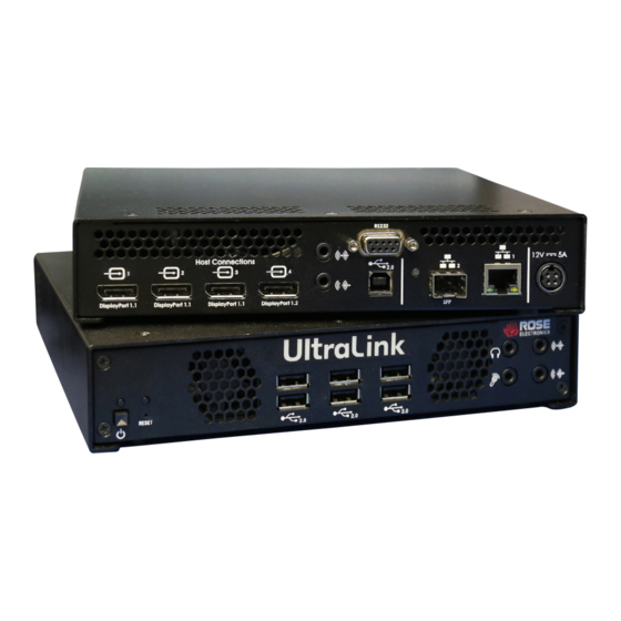
HARDWARE DESCRIPTION UltraLink E-Series Models The UltraLink E-Series is available in the models described below. PCIe Transmitter Cards 2-port Transmitter Card Diagnostic Power LEDs Reset switch Status LED Network Host connections USB Video in ports 1–2 DP 1.1 4-port Transmitter Card Diagnostic Power LEDs Reset switch... -
Page 12: Table 1. Description Of Transmitter Card Connections
Host connections Connect your host computer or video sources here using DisplayPort male to male cables 2-Port model (not supplied). Standard DisplayPort 1.1 resolutions are supported. Maximum resolution depends upon number of ports used. For more information, see DisplayPort video Video in ports 1–2 resolutions. -
Page 13: Transmitter Appliances
Transmitter Appliances 2-port Transmitter Appliance Local connections Power and Status Video loop out USB 2.0 devices Host connections Network and Power in Line in Serial Video in ports 1 – 2 LAN2 LAN1 Power in DP1.1 Line out USB 2.0 4-port Transmitter Appliance Local connections Power and Status... -
Page 14: Table 2. Description Of Transmitter Appliance Connections
Power and Status Illuminates with green, amber, or red either solid or flashing to indicate various conditions of Power LED booting and maintenance. See Transmitter and Receiver Appliance – Power and Status LEDs. Illuminates with green, amber, or red either solid or flashing to indicate various conditions of Status LED peripheral conditions or errors. -
Page 15: Receiver Appliances
Receiver Appliances Remote connections USB and Audio Headphone Line in 2-port Receiver Appliance USB 2.0 Devices x4 Microphone Line out Power and Status Remote connections Video and Serial Network and Power in Video out ports 1 – 2 Serial LAN2 LAN1 Power in DP1.1... -
Page 16: Table 3. Description Of Receiver Appliance Connections
Power and Status Illuminates with green, amber, or red either solid or flashing to indicate various conditions of Power LED booting and maintenance. See Transmitter and Receiver Appliance – Power and Status LEDs. Illuminates with green, amber, or red either solid or flashing to indicate various conditions of Status LED peripheral conditions or errors. -
Page 17: Description Of Led Indicators
Device has detected a fatal error. Try rebooting the card. If the LED is still rapidly Red (fast blink) blinking red after rebooting the card, contact Rose Electronics for technical support. For more information on rebooting see Rebooting or resetting your UltraLink devices. -
Page 18: Figure 7. Transmitter And Receiver Appliance - Power And Status Leds
Transmitter and Receiver Appliance – Power and Status LEDs Figure 7. Transmitter and Receiver Appliance – Power and status LEDs LED color Power LED Status LED Green (solid) Device is active Software is ready Green (slow blink) Device is restarting Green (fast blink) Configuration reset in process Amber (solid) -
Page 19: Figure 8. Transmitter And Receiver Appliance - Lan 1 Network Indicators
Transmitter and Receiver Appliance – LAN1 Network LED Figure 8. Transmitter and Receiver Appliance – LAN 1 network Indicators LED Color LAN 1 (Left LED) LAN 2 (Right LED) No activity detected Transmitting at 1Gbps Green (solid) Green (fast blink) Network activity detected Amber (solid) Transmitting at 100Mbps... -
Page 20: Reset Switch For Rebooting Or Configuration Reset
Reset switch for rebooting or configuration reset Warning: A configuration reset restores the default settings of the UltraLink E-Series device. This resets all of the device settings, including the IP configuration and password. Warning: Point-to-point mode – Performing a configuration reset on a Receiver also resets the configuration of the connected Transmitter. -
Page 21: Preparing Your Ultralink Hardware
Preparing your UltraLink hardware Installing the PCIe Transmitter Card Remove SFP module if installed. Before installing the transmitter card, make sure to remove the SFP module. (For more information, see Removing an Module). Choose an expansion slot. Most systems have different types of expansion slots. Choose a PCIe E®... -
Page 22: Installing An Sfp Module
Installing an SFP module 1. Close the latch handle. 2. Push the module into the SFP cage. Make sure the module is properly oriented. A properly oriented module should slide easily into the housing. 3. Make sure the SFP module is inserted all the way into the housing, When it locks in place, you may hear a “click”. -
Page 23: Connection Precautions
Connection precautions To avoid possible problems that could damage your computers or prevent you from using your UltraLink E-Series product, read the following guidelines before connecting the product. ■ Whenever you change your connection setup, make sure you’re using the correct connectors and that all connectors are properly fastened. -
Page 24: Connecting Your Computers To The Transmitter Appliance
Connecting your computers to the transmitter appliance Connecting host USB The USB cable is provided. Simply connect it from the computer’s USB port to your UltraLink hardware. The PCI Card uses a USB mini-B to A cable. The transmitter appliance uses a USB standard B to A cable. You can use any USB port on the computer including blue USB3.1 super-speed ports. -
Page 25: Connecting Local Access To The Transmitter Appliance
Connecting local access to the transmitter appliance FEATURE NOT ENABLED AS OF FIRMWARE VERSION 3.01 AND IS RESERVED FOR FUTURE USE ■ Local output support (Video out) on the transmitter is expected in an upcoming release. ■ The USB connectors on the front of the transmitter are currently disabled. Optionally connect a DisplayPort monitor to the video loop out connector using a DisplayPort male to male cable (not supplied). -
Page 26: Connecting Your Displays And Devices To The Receiver Appliance
Connecting your displays and devices to the receiver appliance Connecting USB Devices Connect your standard USB devices such as keyboard and mouse here by plugging them in directly. You can also plug in storage device such as flash drive or peripherals such as printers. Note: When using a touch screen monitor USB connection, make sure the monitor is set as the main display in Windows. -
Page 27: Connecting Power To The Ultralink Transmitters And Receivers
Connecting power to the UltraLink transmitters and receivers PCIe Transmitter Card power The card gets its power from the computer and no further connection of power is required. This results in a very neat and compact installation. Since there is no on/off power switch on the card, turning on the computer also powers on the card. -
Page 28: Connecting Network Cable - Point-To-Point And Networked Modes
Connecting network cable — point-to-point and networked modes There are two distinct modes of operation of the UltraLink, either point-to point mode or networked mode. In point-to-point mode, UltraLink E-Series Transmitter and Receiver are directly linked to each other using copper or fiber cable to implement an extender. -
Page 29: Setting Up Point-To-Point Mode
Setting up point-to-point mode 1. Install any transmitter cards in the PC case. 2. Connect all of the cables including the network cable from the transmitter to the receiver and power up the UltraLink devices from their front power switches. 3. -
Page 30: Setting Up Link Redundancy In Point-To-Point Mode
Setting up link redundancy in point-to-point mode Enabling point-to-point link redundancy 1. Connect a second network cable between a Receiver and its Transmitter. 2. Open the OSD at the Receiver, select More Options, and activate Enable link Redundancy. 3. The device will automatically reboot to start the redundant link. Disabling point-to-point link redundancy 1. -
Page 31: Osd Sources Tab In Point-To-Point Mode
OSD Sources tab in point-to-point mode View the input, device, and network information for the transmitter. Figure 26. OSD Sources tab in point-to-point mode Inputs View the video stream information and information about devices connected to the transmitter (Monitor, Microphone, and Line In). Details Provides information about the Transmitter itself (such as the model, serial number, firmware version, and temperature), and shows the connection status and IP address of the device (connected through the... -
Page 32: Osd Receiver Tab In Point-To-Point Mode
OSD Receiver tab in point-to-point mode View and modify the settings for the Receiver. Figure 27. OSD Receiver tab in point-to-point mode Audio settings For audio input and output, click the Enable audio option. To adjust the audio settings for connected devices: Headphone audio source Select the Transmitter audio source for the headphone... -
Page 33: Table 12. Receiver: Monitor Settings
Monitor settings When enabled, the receiver examines the monitor’s display modes listed in its EDID and only allows modes that are part of the EDID. If the source system is sending a video resolution that’s not part of the Optimize video mode monitor’s EDID, then the receiver will use the closest match and/or scale compatibility with monitors the resolution. - Page 34 Input and output information View the connection information of the devices (Monitor, Microphone, and Line In) connected to the selected Receiver. Details Provides information (such as the model, serial number, firmware package version, and temperature) on your device, and provides the connection status and IP address of the device (connected through LAN). Get logs Provides detailed logs that are useful for auditing and troubleshooting.
-
Page 35: Setting Up Networked Mode
Setting up networked mode 1. Install any transmitter cards. 2. Connect all of the cables from the UltraLink transmitters/receivers and your DHCP server to the Ethernet switch. 3. Power up the Ethernet switch and once it and the DHCP server are operational, power up the UltraLink devices. -
Page 36: Setting Up Link Redundancy In Networked Mode
Setting up link redundancy in networked mode Link redundancy ensures UltraLink E-Series devices continue to work in case of a network switch or cable failure. Redundant Links can be employed for Networked mode devices and Point-to-point devices. NOTE: Redundancy is not supported on Transmitter Cards. Networked mode Connection guidelines ■... -
Page 37: Installing Rose Ultralink Device Manager Software
Obtaining UltraLink Device Manager software To obtain the latest UltraLink Device Manager software, go to www.rose.com/products/ultralink-e-series contact your Rose Electronics representative. Installing UltraLink Device Manager software Run the installation program on any computer on the network with one of the supported operating systems and follow the on-screen instructions. -
Page 38: Accessing The Osd In Networked Mode
Accessing the OSD in networked mode For devices connected in Networked mode, the OSD enables Receiver log in and switching to Transmitters. The OSD is available on UltraLink E-Series Receivers. To display the OSD, enter the OSD keyboard shortcut on the keyboard connected to the receiver. The default keyboard shortcut is the ScrollLock key. Note: To use the OSD and enable networked mode, make sure to obtain a user name and password from the network administrator. -
Page 39: Osd Sources Tab In Networked Mode
OSD Sources tab in networked mode Figure 29. OSD Sources tab in networked mode For the transmitters to be displayed in the Sources tab, an allowed connection must first be set between your UltraLink E-Series transmitter and receiver (see the UltraLink Device Manager User Guide). To view information about a source, select the Sources tab and select a transmitter Switching to a different transmitter 1. -
Page 40: Osd Receiver Tab In Networked Mode
OSD Receiver tab in networked mode Figure 30. OSD Receiver tab in networked mode Settings Control the settings of analog audio inputs and outputs (Line in, Audio Microphone, Line Out, and Headphone) Aggregator mode only – To change a monitor layout for aggregator mode, click Change monitor layout. -
Page 41: Aggregator Mode
Aggregator Mode With Aggregator mode, UltraLink E-Series receivers can display video streams from multiple Transmitters in a single layout. Figure 31. Aggregator mode Aggregator prerequisites: ■ Make sure the Fixed EDID option is enabled. Aggregator mode requires Fixed EDID. ■ ®... - Page 42 Configuring aggregator mode 1. Create the monitor layout. Select the OSD Receiver tab, then click Monitors, and then click Change monitor layout. A dialog box will be displayed. Select a layout for the monitors, then drag the displays into the layout, and click OK. 2.
-
Page 43: Figure 32. Creating An Aggregate Mode Layout
Figure 32. Creating an Aggregate Mode Layout Remove a video stream from the monitor layout by: ■ Right-clicking the video stream icon in the layout. ■ Dragging the video stream icon and dropping it anywhere outside of the layout. Removing a layout To remove a layout, use the following steps: 1. -
Page 44: Figure 33. Osd Dynamic Sources Tab
Switching between dynamic sources The dynamic source in an aggregator mode grouping can be changed as frequently as necessary. 1. Open the OSD and click the Dynamic sources tab. The tab shows all the source streams from accessible Transmitters. Each source is displayed as a preview image, the name assigned to the Transmitter, and the source input number. -
Page 45: Rebooting Or Resetting Your Ultralink Devices
Rebooting or resetting your UltraLink devices This section describes how to reboot or perform a configuration reset of your UltraLink E-Series card or appliance When to reboot or reset your device What to do … When to do it … What the result is …... -
Page 46: Hardware Reboot Or Configuration Reset Using The Reset Switch
Hardware reboot or configuration reset using the reset switch Warning: A configuration reset restores the default settings of the UltraLink E-Series device. This resets all of the device settings, including the IP configuration and password. Warning: Point-to-point mode – Performing a configuration reset on a Receiver also resets the configuration of the connected Transmitter. -
Page 47: Updating Ultralink E-Series Firmware
Updating UltraLink E-Series firmware Note: Your UltraLink E-Series products may ship with an older firmware version. Before using the UltraLink products, you must update the firmware version installed on the devices to use the version of your deployed release. All UltraLink E-Series devices must use the same version of the firmware. Before you update any firmware, please read the following guidelines: ■... -
Page 48: Firmware Update Procedure - Networked Mode
Firmware update procedure – networked mode Please check with Rose Electronics for the latest firmware updater package available for the UltraLink E- Series products. Note: If you’re using networked mode, make sure the firmware version matches the version of the UltraLink Device Manager software installed on your controller system. -
Page 49: Figure 38. Update Firmware - Authentication Dialog For Devices With A Password
3. Using automatic detection To search for devices on your subnet, using Automatic detection, click Search. Wait while the Updater finds the devices and answer the authentication dialog detailed in step 5. If the devices are present on your subnet, then all devices should be found. If your network is more complicated than a simple subnet you may need to use the manual detection method in step 4. -
Page 50: Figure 39. Update Firmware - Authentication Dialog For Devices Without A Password
If you’re updating multiple devices, enable the Use these credentials for all remaining devices check box. If you don’t know the password of some of the devices on your network, enable Skip all remaining devices with unknown passwords. Enabling this option ignores the devices that don’t use any of the passwords already entered. -
Page 51: Troubleshooting
Consult the firmware release notes. See Appendix F – Firmware release notes version 3.01.00 If your problem persists, contact Rose Electronics Common problems and solutions This section addresses specific problems for your UltraLink product that could prevent you from using your system or product. - Page 52 Problem: Random display flickering occurs while using a point-to-point connection Cause Your video output is unstable, or you may be using a fixed frequency monitor Solution Point-to-point mode only – In the OSD, click Settings > Monitors. Make sure the Stabilize display output option is enabled Problem: Random display flickering occurs, or on-screen message (“Frame rate conversion or video scaler on”, “Frame rate conversion on”, or “Video scaler on”) appears...
-
Page 53: Safety
Safety The UltraLink E-Series product, like all electronic equipment, should be used with care. To protect yourself from possible injury and to minimize the risk of damage to the Unit, read and follow these safety instructions and also review your warranty for more information. ... - Page 54 Only use power supplies originally supplied with the product or use a replacement that’s approved by Rose Electronics. Don’t use the power supply if it appears to be defective or has a damaged housing. Don’t defeat the safety purpose of the polarized or grounding-type plug. A polarized plug has two blades with one wider than the other.
-
Page 55: Maintenance And Repair
The products do not contain any internal user-serviceable parts. In the event a Unit needs repair or maintenance, you must first obtain a Return Authorization (RA) number from Rose Electronics or an authorized repair center. This Return Authorization number must appear on the outside of the shipping container. -
Page 56: Appendix A - Specifications
APPENDICES Appendix A – Specifications Cables (maximum distance in point-to-point mode) Cat5e, CAT6 328 ft (100 meters) OM2, OM3, OM4 (50/125μm) 1,805 ft (550 meters) multimode cable OM1 (62.5/125μm) 902 ft (275 meters) multimode cable OS1, OS2 (9/125μm) 3.10 miles (5 Km) single mode cable External power supply (Appliance models only) Input AC voltage range 100V to 240V... - Page 57 Transmitter Appliance Receiver Appliance 2-port 4-port 2-port 4-port Dimensions (WxDxH) 8.526 in x 7.45 in x 1.676 in / 216.6 mm x 189 mm x 42.6 mm Form factor 1RU, half-width 1RU, half-width 1RU, half-width 1RU, half-width DisplayPort V1.1 DisplayPort V1.2 Yes (on port#4 only) Yes (on port#4 only) 4×1920×1080@60Hz...
-
Page 58: Appendix B - Part Numbers
Appendix B – Part Numbers Part number Product description UltraLink E-Series Receiver Appliance, 2xDisplayPort 1.1, 4xUSB-A, audio 3.5mm, ULE-RXA2 resolution up to 1920x1200@60Hz (2-ports), or 2560x1600@60Hz (1-port), 1xRS232(M), 1xRJ45, 1xSFP UltraLink E-Series Receiver Appliance, 3xDisplayPort 1.1 and 1xDisplayPort 1.2, 6 USB ULE-RXA4 type-A, audio 3.5mm resolution up to 4K/60 4:4:4, 1xRS232(M), 1xRJ45, 1xSFP UltraLink E-Series Transmitter Appliance, 2xDisplayPort 1.1, 1xDisplayPort 1.1 (local),... -
Page 59: Ultralink E-Series Network Firewall Requirements
UltraLink E-Series network firewall requirements Network port Type Inbound Outbound Functionality 20,21 FTP: File upload SSH: Firmware update DHCP: DHCP client NTP: Network time protocol SNMP: Network management (public community string) HTTPS: UltraLink Device Manager commands and 443* firmware updater authentication 1900* UPnP: Microsoft SSDP for discovery of UPnP devices RTP/RTCP: Audio and video streams and control... -
Page 60: Adding Rules To Your Windows Firewall Settings
Adding rules to your Windows Firewall settings Note: You may need administrator rights to modify your Windows Firewall settings. For more information, see Windows documentation or contact your system administrator. 1. Windows 10 – Click Start Settings Network & Internet Ethernet Windows Firewall. -
Page 61: Appendix D - Rack-Mounting Options
Appendix D – Rack-mounting options Mounting guidelines To prevent damage to your product, read the following guidelines before mounting your UltraLink hardware: ■ Make sure not to block the ventilation holes on your device. ■ Don’t stack anything directly over the device. ■... -
Page 62: Appendix E - Configuring Your Audio Settings
Appendix E – Configuring your audio settings ® Note: We recommend you review your system’s Windows audio settings to know which DisplayPort output is configured to use audio. Receiver output Standard mode Aggregator mode Audio source from transmitter When receiver connects to a When receiver connects to unique transmitter multiple transmitters... -
Page 63: Receiver Input
Receiver input Standard mode Aggregator mode Audio source from receiver When receiver connects to a unique When receiver connects to transmitter multiple transmitters No audio available on any of the No audio available on the Line Out Disabled Line Out connectors of the connector of the transmitter. -
Page 64: Appendix F - Firmware Release Notes Version 3.01.00
Appendix F – Firmware release notes version 3.01.00 Notes and limitations ■ Aggregator mode – The Link Redundancy feature isn’t currently supported while using aggregator mode. ■ Guest connections – With guest connections, the following aren’t currently supported: RS232, audio Line In and microphone. -
Page 65: Known Issues
Known issues ■ After adding a new Tx device and configuring it using UltraLink Device Manager software, it can take up to 45 seconds for the new Tx device to appear in the OSD as an available connection option for the ■... -
Page 66: Appendix G - Declaration Of Conformity
Appendix G – Declaration of Conformity This equipment has been tested and found to comply with the limits for a Class A digital device, pursuant to Part 15 of the FCC Rules. These limits are designed to provide reasonable protection against harmful interference when the equipment is operated in a commercial environment. - Page 67 Ces unités sont conformes à la directive communautaire 2014/30/EU pour les unités numériques de classe A. Les tests effectués ont prouvé qu’elles sont conformes aux normes EN55032/CISPR32 et EN55024/CISPR24. Le fonctionnement de ces produits dans un environnement résidentiel peut causer des interférences radio, dans ce cas l’utilisateur peut être amené...
- Page 68 ▪ ▪ WWW.ROSE.COM sales@rose.com (800) 333-9343 ▪ ▪ Rose Electronics 10707 Stancliff Road Houston, Texas 77099 Rose USA (281) 933-7673 ▪ Rose Europe ▪ Rose Asia +65 6324 2322 Rose Australia +61 (0) 421 247083 WWW.ROSE.COM...
Need help?
Do you have a question about the UltraLink E Series and is the answer not in the manual?
Questions and answers