Table of Contents
Advertisement
Advertisement
Table of Contents

Related Manuals for BAC NEXUS NXF-0403N-CS2TS-H1


Summary of Contents for BAC NEXUS NXF-0403N-CS2TS-H1
- Page 1 OPERATION & MAINTENANCE MANUAL...
- Page 2 Check and adjust water level in the spray water basin Check operation of pump(s) Inspect and clean conductivity sensor Check basin heater and stand alone BAC heater control panel (optional) Drain spray water basin and connected piping Inspect hCore® Heat Transfer Technology...
-
Page 3: Table Of Contents
® PART 6 Operation Considerations for Accessories Emergency hCore Heat Transfer Technology Drain ® Basin Heater and Stand Alone BAC Heater Control Spray Water Basin Protection Panel Resonant Speed Identification Procedure PART 2 Storage & Extended Shutdown Positive Closure Dampers (PCDs) -
Page 4: Safety Precautions
Safety Precautions DANGER DANGER: Rotating equipment will cause severe personal injury or death to persons who come in contact. Do not perform any service, maintenance, or inspection on or near the fan(s), motor(s), or inside the unit without first ensuring that the fans and pump motors are disconnected, locked out, and tagged out. -
Page 5: Equipment Precautions
NOTICE • BAC units are typically installed immediately after shipment and many operate year round. However, if the unit is to be stored for a prolonged period of time either before or after installation, certain precautions should be observed, as outlined in “Storage & extended Shutdown”... -
Page 6: Start-Up & Operation
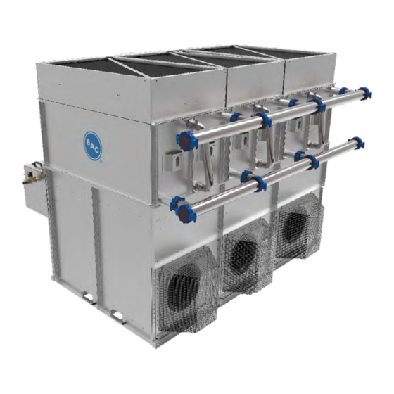
NEXUS MODULAR HYBRID COOLER ® Start-Up & Operation Figure 1. Nexus Modular Hybrid Cooler ® WWW. B A LT IM ORE A IRCOIL.COM... - Page 7 Start-Up and Operation 1. hCore Heat Transfer Technology: Exclusive closed loop heat transfer section with ® stainless steel construction that offers high corrosion-resistance. Nexus Modular Hybrid Cooler ® 2. Fluid Connections: Fewest field piping connections due to innovative, easy-to-install manifold with grooved connections. 3.
-
Page 8: Start-Up
Start-Up General • If the unit will be in storage prior to start-up, follow the “Prolonged Outdoor Storage” instructions on page 17. • It is strongly recommended to install a removable 1/16” mesh strainer upstream of the process fluid inlet to prevent large debris from entering the hCore® Heat Transfer Technology (closed loop heat transfer section). - Page 9 • Remove spray distribution access panels, and inspect and clean the spray branch, Start-Up & Operation nozzles, and drift eliminators as necessary. • Remove all dirt and debris from the fan guard(s). Start-Up • Open hinged access fan panel (see Figure 4) to clean all mechanical components and General to remove dirt and debris from plenum area.
- Page 10 • Remove excess and loose sealer tape from valves and connections, including flume connections. • Turn the water supply on. • Set the make-up float valve so the water shuts off at the operating level, see Table 2 DANGER: Rotating equipment on page 22 and Figure 17 on page 23.
- Page 11 • Refer to “iPilot Control System Appendix” on page 45 for more information ® including for controls connections. • Anytime equipment operation is required, Run Enable must be turned On Start-Up & Operation either locally through the iPilot Control System interface or remotely with a ®...
- Page 12 For Local Control with a BMS Interface Unit Run Authorization Disabled • Ensure that the BMS is wired properly per wiring diagram located in the iPilot Control ® System. • Navigate to BMS Communication screen and select your communication type (Modbus or BACnet).
-
Page 13: Operation
– Conductivity-based Bleed: Conductivity threshold value for bleed (recommended) Start-Up & Operation – Time-based Drain: Time and frequency of complete basin drain (optional) • PI-Parameters Start-Up – Prop. Band – Proportional band of PI controller Start-up – Integr. Time – Integration time of PI controller Operation Control System Appendix”... -
Page 14: Spray Water Basin And Pump Water Control
Water Saver Mode Maximum Water Savings MAXIMUM WATER SAVINGS In Water Saver Mode, water savings are maximized by leveraging the dry efficiency of the hCore Heat Transfer Technology and operating ® without spray water. To meet increasing loads, the EC Fan System will automatically and intelligently increase speed and the spray pumps will activate only when necessary (Winter Guard Disabled). -
Page 15: Maintaining Water Quality
Start-Up & Operation Maintaining Water Quality Operation Water Saver Mode The iPilot Control System is preset at the factory in accordance with BAC’s Water Quality ® Spray Water Basin and Pump Guidelines. Water quality can be controlled as follows: Water Control •... -
Page 16: Hcore ® Heat Transfer Technology Freeze Protection
• When the optional basin heaters are not included: – Once ambient temperature drops below 35°F (1.7°C), water will remain in the basin for 1 hour and then the water will be drained. – The solenoid make-up valve will remain closed until the ambient temperature is NOTE: For the units with the heater above 35°F (1.7°C) and when evaporative cooling is required. - Page 17 Positive Closure Dampers (PCDs) (Optional) Start-Up & Operation The amount of auxiliary heat required can be substantially reduced by the use of positive Cold Weather Operation closure dampers at the unit air discharge (see Figure 11). The dampers remain open as long as the unit run state is active and remain closed whenever run state is inactive.
-
Page 18: Emergency Hcore ® Heat Transfer Technology Drain
45ºF (7.2°C). For more information, see “Detailed Component Maintenance Procedures” on page 20. Contact your local BAC Representative for guidelines on the installation of an emergency hCore Heat Transfer Technology drain system. -
Page 19: Storage & Extended Shutdown
“Corrosion Protection” on page 30 for more details. Motor Recommendation BAC standard motors are designed for storage at ambient temperatures of -13ºF to 104ºF (-28.9ºC to 40ºC). Prolonged periods of exposure above or below these specified conditions could degrade components of the motor and cause malfunction or premature failure. - Page 20 • Reinstall all components, panels, and drain plugs (as applicable), and remove all protective coverings. • For units stored prior to installation, conduct rigging procedures as directed in the unit’s Rigging and Assembly Instructions, by contacting your local BAC Representative. • Perform an insulation test to ensure satisfactory insulation resistance.
-
Page 21: Extended Shutdown
Heat Transfer Technology must be protected from ® Extended Shutdown freezing. For protection against hCore Heat Transfer Technology freeze-up, BAC ® recommends the use of an inhibited glycol solution. If protecting the hCore Heat ®... -
Page 22: Detailed Component Maintenance Procedures
NEXUS MODULAR HYBRID COOLER ® Detailed Component Maintenance Procedures hCore Heat Transfer Technology ® The hCore Heat Transfer Technology is an exclusive closed loop heat transfer section with ® stainless steel construction that offers high corrosion-resistance. NOTE: This is a cutaway view of the hCore Heat Transfer Technology. -
Page 23: Ec Fan System
• To drain the hCore Heat Transfer Technology on models without a crossover pipe, ® Detailed Component drain the system piping as necessary to remove fluid from the hCore® Heat Transfer Maintenance Procedures Technology using a centrally located drain valve. hCore Heat Transfer ®... -
Page 24: Diamondclear ® Design
DiamondClear Design ® The DiamondClear Design is a water-management system which provides continuous self- ® cleaning, significantly cutting water basin maintenance costs by reducing scale build-up and biological growth. It can also help reduce the need for traditional water treatment. The DiamondClear Design includes the following components: ®... - Page 25 Solenoid Make-up Valve Detailed Component Water Diverter Maintenance Procedures Mechanical Make-up Access Panel Valve DiamondClear Design ® Overflow Spray Water Basin Spray Pump Drain Valve High/Low Level Switches Figure 17. Spray Water Basin Multi-module units have a continuous spray water basin with a single mechanical make-up valve, solenoid make-up valve, high/low level switches, overflow, and drain valve.
- Page 26 • Maintain the make-up water supply pressure between 20 and 75 psig for proper operation. BAC recommends a surge protector (provided by others) for pressures over 60 psig. • The basin water level will be factory-set. However, if additional adjustments are required, set the basin water level by adjusting the float ball so that the valve is completely closed at the operating level shown in Table 2 on page 22.
- Page 27 Water Diverter Detailed Component The water diverter can be accessed by opening the panel located behind the spray water Maintenance Procedures basin. Quarterly, inspect and remove any trash or debris that may have accumulated from the water diverter and flush with fresh water using a standard garden hose. This will DiamondClear Design ®...
- Page 28 Drift Eliminators The drift eliminators are made of PVC (optional steel drift eliminators are available), which is impervious to rot, decay, rust, or biological attack. Quarterly, inspect drift eliminators and remove dirt and debris. WARNING: The top horizontal surface of the unit is not intended to be used as a walking surface or working platform, and all maintenance should be done from...
-
Page 29: Ipilot ® Control System
Components Detailed Component The iPilot Control System contains the following components: ® Maintenance Procedures Solenoid Make-up Valve DiamondClear Design ® Check the nameplate for correct catalog number, pressure, voltage, frequency, and service. Water Diverter Ensure that the incoming water pressure does not exceed the valve rating. Solenoid make- iPilot Control System ®... - Page 30 Conductivity Sensor • The conductivity sensor should be cleaned periodically. The frequency of cleaning will vary by installation. NOTE: BAC recommends adjusting • To determine how often the probe must be cleaned, follow the procedure below: the conductivity setpoint in the –...
- Page 31 Software Verification for a pCO Controller If a BAC Factory Technician is troubleshooting the controller over the phone, they may ask for the software version. To provide them with the information, follow these steps from the control panel screen (refer to the “iPilot®...
-
Page 32: Optional Uv System
Optional UV System The optional UV System is designed to reduce bacterial growth, and it is fully-integrated into the Nexus cooler and iPilot Control System. Before performing any maintenance, follow the proper lockout / tagout procedures. Intensity Sensor UV Reactor (quartz sleeve and bulb inside of reactor) Ball Valve Circulation Pump... - Page 33 • Lift the rotor/impeller unit to ensure it is free of foreign matter. o Be sure to lift the rotor/impeller unit straight out of the motor cavity to prevent damage to the bearing support. UV Bulb o There will be a magnetic force resisting removal of the rotor/impeller. o Use gentle, but steady lifting forces, and use fingers only.
- Page 34 Ultraviolet (UV) Quartz Sleeve Ultraviolet (UV) Quartz Sleeve Quarterly, and when indicated by the low UV intensity alarms, ensure that the Quartz sleeve Quarterly, ensure that the Quartz sleeve located inside of the UV cha located inside of the UV chamber is clean and free of dirt or scaling. Throughout normal scaling.
- Page 35 UV Intensity Sensor Quarterly, and when indicated by the low UV intensity alarms, ensure that the intensity sensor located on the top exterior of the UV chamber is clean and free of dirt or scaling. Throughout normal operation, minerals in the water will slowly form a coating on the intensity UV Intensity Sensor sensor window.
-
Page 36: Water Treatment
• Thermosetting Hybrid Polymer Components: Inspect the components protected with the thermosetting hybrid polymer for scratches, scrapes, or blemishes. To cosmetically touch up these areas with color matched polymer, use BAC Part #160133 available from your local BAC Representative. • Stainless Steel Components: Inspect stainless steel components for signs of blemishes or corrosion. -
Page 37: Corrosion And Scale Control
• A qualified water treatment professional must be consulted to develop a water treatment plan for the times that the unit does operate wet. • With all the combined benefits outlined above, a biological control plan may be all Corrosion Protection that is necessary for many applications. -
Page 38: Chemical Treatment Requirements
• The chemicals must be compatible with the specific unit materials of construction. • BAC generally discourages acid dosing as means of scale control. Should acid dosing be utilized, the acid should be injected at a point in the system where total mixing and dilution occur, such as the water treatment connections in the spray water basin. -
Page 39: Alternative Water Sources
BAC’s Manufacturing Process steel. BAC takes precautions to prevent cross-contamination, processing galvanized and stainless NOTICE: Never use chloride or steel parts separately. Also, stainless steel brushes are used to clean welds on stainless parts and care is taken to avoid scratching parts during processing. -
Page 40: System Cleaning
• If the metal chips are not removed with the Scotch-Brite™ Products, electro-chemical cleaning may be required. BAC uses commercially available equipment for electro- chemical cleaning in the field. Contact your local BAC Representative for more information. System Cleaning... - Page 41 hCore Heat Transfer Technology Cleaning ® Corrosion Protection The outside of the hCore Heat Transfer Technology (closed loop heat transfer section) ® may require occasional cleaning. The chemicals used must be compatible with all of the Long Term Care of Stainless Steel materials that will be contacted.
-
Page 42: Bleed Rate
NEXUS MODULAR HYBRID COOLER ® Bleed Rate In evaporative cooling, evaporation of a small portion of the recirculating spray water as it flows through the equipment causes the cooling effect. As this water evaporates, NOTE: A proper water treatment the impurities originally present remain in the recirculating water. The concentration of program, administered under the the dissolved solids increases over time and can reach unacceptable levels. -
Page 43: Example To Estimate Bleed Rate
NOTE: Evaporation is proportional E = Q * R * 0.001 = 300 * 10 * 0.001 = 3 USGPM to the load and will vary seasonally. BAC includes a conductivity sensor = 250 ppm = 5.55 to maximize water conservation. -
Page 44: Operation Considerations For Accessories
Ensure that the heating element is completely submerged before energizing the main Figure 32. Basin Heater disconnect. The basin heater option includes a stand alone BAC heater control panel and a combination temperature/water level sensor. The stainless steel sensor probe with 1/2”... -
Page 45: Basin Heater And Stand Alone Bac Heater Control Panel
Operation Refer to the wiring diagram provided in the submittal package, also located on the inside Basin Heater and Stand Alone BAC Heater Control Panel of the heater control panel door. Ensure that the element is completely submerged before (Optional) energizing the main disconnect. -
Page 46: Resonant Speed Identification Procedure
• Enter the unit, and carefully remove the accelerometer, along with any associated wiring from the unit. • Contact BAC to enter the lockout speed ranges, if any have been identified, so that the unit will not operate at a resonant speed. -
Page 47: Positive Closure Dampers (Pcds)
Operation Considerations Positive Closure Dampers (PCDs) (Optional) for Accessories Resonant Speed Identification The dampers remain open while the unit run state is active and close when the run state Procedure is inactive. Positive Closure Dampers (PCDs) Ensure that the actuator linkages are tight and the dampers are opening and closing. Refer to “Positive Closure Dampers (PCDs)”... -
Page 48: Part 7 Troubleshooting Guide
Restart the unit and ensure all fans are operational and make sure the fan spins in right direction, and if it does not contact your local BAC representative. Ensure the communications cable is connected to the controller on port J26. - Page 49 Ensure OSV status for all the components is “NO” OSV status is “Yes” Table 4. Troubleshooting Guide (Continued) Replacement Parts To order replacement parts, contact your local BAC Representative. W WW.BALTIMOREAIR C OIL.C O M W WW.BALTIMOREAIR C OIL.C O M...
- Page 50 iPilot Control System Alarm Descriptions ® The iPilot Control System has been designed with alarms and notifications to provide operating status and ® ensure that the equipment is operating properly. Table 5 shows all the alarms and warnings on Nexus Modular ®...
-
Page 51: Menus
NEXUS MODULAR HYBRID COOLER ® Appendix: iPilot Control ® System Menus The following information describes how to adjust settings within the user interface. Main Menu Screen Alarm Program Enter Down Escape Figure 34. Main Menu W WW.BALTIMOREAIR C OIL.C O M W WW.BALTIMOREAIR C OIL.C O M W WW.BALTIMOREAIR C OIL.C O M... - Page 52 User Interface Keys and Functions Button Name Description This button illuminates red when an alarm is present; and pressing the Alarm button will display the alarm description. Displays all the main submenus. Brings the menu back to the previous screen. Up and Down Scrolls through options.
- Page 53 System Information Appendix: iPilot ® Software information and OS version can be retrieved. Control System Menus Main Menu Screen User Menu Points Overview System Information Clock Menu Alarm Logs Clock Menu This is to setup system time, date and time zone for different regions. Alarm Logs System alarm and warning information can be retrieved.
-
Page 54: Software Menus
Software Menus Menu Overview Screen Menu Function Ref. Readout: • Unit status (ON/OFF) • Fluid outlet and ambient temperature Main loop • Fan speed – Energy saver mode • Fan speed – Water saver mode • Fan status Set: • Local ON/OFF •... - Page 55 Main Loop Appendix: iPilot ® The screens in the main loop are read only and are non-editable. Control System Software Menus Screen Screen Description Menu Overview Ref. Main Loop Main screen with general information: NOTE: When unit status is ON, the •...
- Page 56 Italian, French, Dutch, Spanish or German. • “Unit System”: Sets the unit of measure of controls to US, UK, CANADA, LONDON, SI • “Site”: BAC job number (starts with “U...”) for the job site reference. • “Operating Mode”: Select the operating...
- Page 57 Appendix: iPilot Screen ® Screen Description Ref. Control System BMS Communication: Enable/disable and define Software Menus communication type User Menu (E) • “Choose Comm Type”: None, Modbus RTU, Modbus IP, BACnet/MSTP, BACnet/IP • “BMS On/Off Control”: No/Yes Configure options for ModBUS RTU Configure options for BACnet MSTP Configure options for BACnet IP Table 9.
- Page 58 Screen Screen Description Ref. Alarm detection delays: • “Alarm delay”: Time delay for EC fan alarms and warnings. • “Sensor alarm delay”: Time delay for alarms from the fluid outlet temperature and ambient temperature sensor. • “Network comm. Loss delay”: Time delay for the loss of communication between units (only available for BMS and Customer Input Modes).
- Page 59 Point Overview Menu (V) Appendix: iPilot ® The screens in Point Overview are developed to troubleshoot and test different components Control System in Manual Mode. Software Menus Screen Screen Description User Menu (E) Ref. Point Overview Menu (V) Shows operating values (read only) •...
- Page 60 Screen Screen Description Ref. Exporting system Alarm/Warning • File Destination: Specify destination • File name: Al_EXPORT_00 • Confirm: YES/NO NOTE FOR V07 AND V08: For exporting the file to USB, switch off the main disconnect on the control panel and the main door, and insert Exporting system Data Log history the USB into the controller.
- Page 61 System Information (S) Appendix: iPilot ® The screens in the System Information are read only and cannot be edited. Control System Software Menus Screen Screen Description Ref. Point Overview Menu (V) System Information (S) • “SW Ver.”: Current Software Version Clock Menu (C) installed Alarm Logs (Record)
-
Page 62: Controls Connections
– The 4-20mA signal commands the fans off at 4mA and full speed at 20mA BMS Communication (Optional) • Communication through Modbus over RS485 or TCP/IP. For RS485 connection, BAC recommends the use of twisted shielded paired wire with a ground. - Page 63 Operation Mode BMSModeSw 40906 1701 UINT Write Mode / Water Saver Mode UnitLogic.BMSWtrCond- Read / µΩ/cm (default per BAC Conductivity Setpoint 40907 1602 REAL StPt Write water quality guidelines) Table 15. BMS Points Table W WW.BALTIMOREAIR C OIL.C O M...
- Page 64 Fluid Temp Setpoint BMSLWTStPt 40911 1601 REAL Write setpoint Unit Status UnitStatus 30907 1402 DINT Read On / Off BAC Unit Number BACUnitNo 30905 1405 UDINT Read Uxxx Water management Read / Enable / disable time-based BMS_WMTmBleedEnble 1303 BOOL Time Bleed Enable...
- Page 65 Appendix: iPilot ® Control System Software Menus Alarm Logs (Record) Point ModBUS BACnet Read / Variable Datatype Comment Description Address Write Read / Unit of Measure BMS BMS_UnitofMeasure 40922 1710 USINT Unit of measure Write AlarmMng.AlrmResBy- Read / Alarm Reset 1312 BOOL Manual reset of alarms...
- Page 66 COOLING TOWERS CLOSED CIRCUIT COOLING TOWERS ICE THERMAL STORAGE EVAPORATIVE CONDENSERS HYBRID PRODUCTS PARTS & SERVICES w w w . B a l t i m o r e A i r c o i l . c o m 7600 Dorsey Run Road, Jessup, MD 20794 ›...
Need help?
Do you have a question about the NEXUS NXF-0403N-CS2TS-H1 and is the answer not in the manual?
Questions and answers