Advertisement
Quick Links
Advertisement

Related Manuals for Disaster Area Designs SMARTClock Gen3


Summary of Contents for Disaster Area Designs SMARTClock Gen3
- Page 1 SMARTClock Gen3 User Manual ...
- Page 2 Revision History: v1.00b Updated for use with v1.00d firmware v1.00a 6/24/17 Added further information about the pull-up DIP switch Added info about nCLK modes for MultiJacks v1.00 05/24/2017 Initial Release Disaster Area Designs SMARTClock Gen3...
- Page 3 SAVING AND LOADING PRESETS To save the current settings to a preset, hold the Edit Knob down. The SMARTClock Gen3 settings will be saved to the current preset slot. If NAMES are enabled in the SMARTClock settings, the display will flash the current name before saving. Tap the Edit Knob to choose a letter to edit, rotate the Knob to move from one letter or character to the next.
- Page 4 Connecting the SMARTClock Gen3 There are several ways to connect your devices: Tap Tempo Outputs: Connect your device’s tap tempo input jack to one of the available tap tempo outputs on the SMARTClock using a standard mono patch cable. All four outputs are configured to control normally-open tap tempo inputs, which is the most common type.
- Page 5 So maybe you have an amplifier with channel switching? Or a pedal with a remote switch or “favorite” input? The SMARTClock Gen3 can handle that. Configure one or more of the SMARTClock’s outputs as TOGGLE and then you can set your amp channels or favorite switch functions to change with your SMARTClock presets! Connect to your amp or pedal using a mono cable.
-
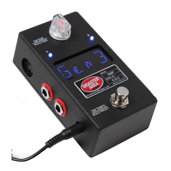
Page 6: Controls And Connections
Standard DC power supply input, 9V center negative. The SMARTClock Gen3 requires approximately 80mA. Main Outputs A & B: The red connectors on the left side are the main outputs of the SMARTClock Gen3. These two outputs connect to your tap tempo devices and keep them all in sync. These outputs are electrically isolated to prevent noise or other problems, and have an optional pull-up function that allows them to work with almost any device capable of receiving tap tempo. - Page 7 Setting Up the SMARTClock Gen3 The SMARTClock Gen3 is set up from the factory to control 4 tap tempo devices, and to respond to incoming MIDI messages on channel 16. To change the device settings, power the SMARTClock off and back on, then hold the Edit Knob down when the display scrolls DISASTER AREA.
-
Page 8: Dip Switches
MultiJack Setup The two white jacks on the right side of the SMARTClock Gen3 are our amazing MultiJacks. These jacks are normally set up to function as tap tempo or remote switch outputs, but they may also be set up to work as footswitch inputs our MIDI outputs. -
Page 9: Midi Input And Output
To engage interface mode, power on the SMARTClock while connected to a USB host such as a PC or Mac. While the display is scrolling, hold the footswitch down. The display will show “INT” and the SMARTClock will be in interface mode. To exit interface mode, power cycle the SMARTClock. Disaster Area Designs SMARTClock Gen3...
Need help?
Do you have a question about the SMARTClock Gen3 and is the answer not in the manual?
Questions and answers