Table of Contents
Advertisement
Quick Links
QUICKSTART "BASIC" WIRELESS TRACKER EXPANSION BOARD TO WIRELESS BASEBOARD RELAY 2 GUIDELINES
For COMPLETE installation instructions, please refer to the instruction sheets included with the wireless
kits, Wireless Layout and Start-Up Guide and the HARDwired Installation/Owner's manual P/N 2358-065.
Access Control System Board
RS 232
MIC
VOL
3 2 1
SPK
VOL
FEED
BACK
3 2 1
CLK
SEN
ON
Relay 0
MASTER
CODE
OFF
KEYPAD
NO NC
C
NO
NC
RING
13
14
1
2
3
4
5
6
7
8
9
10
11
12
15
16
17
18
19
20
2C
2RY
PHONE
CGND
PSW
MIC
COM
SPKR
IMD
5VDC
IMC
Z
A
1C
1NC
1NO
BAT
16AC
16AC
Central Office
phone line -
Switch closure across
touch tone,
terminals 4 & 6 will
loop start.
activate relay 1 for its
programmed strike time.
Relay 2
(Postal Lock)
Jumper
Main Door/Gate
Relay 1 or Relay 0
Relay 1
Important Note: Relay 2 is used to control
wireless tracker expansion board addresses
3-10, Relay 1 or Relay 0 can be used as the
Primary Relay that will open a visitor door or
Relay 2
gate when the resident pushes "9" on their
telephone.
Relay 2 gets activated by Wiegand 2 input.
Start-Up Wireless Communication Between Boards after Installation is Complete
Steps 1-4 MUST be performed on EACH wireless tracker expansion board used in the entire system. Power down the other wireless
tracker expansion boards used in the system while performing these 4 steps on each board. See reverse side for more information.
CH
8
8
1) Channel Number
and RF ID Number
NET
must match on baseboard and all tracker expansion boards.
ID
RF RANGE
2) RF Range adjusted to Max (full clockwise) on each board.
3) Press Program Button on each board to save settings.
PROGRAM
4) Press Reset Button on each board to reboot boards.
RESET
After the 4 steps have been preformed:
•
RF SYNC LED will blink BLUE on each board while establishing communication between boards. This may take up to 20 sec.
•
RF SECURE LED on tracker expansion board will turn steady RED when communication has been SUCCESSFULLY established.
Antenna Options
Antenna Mount
Wireless Repeater
P/N 2364-080
Range is approximately
ELEVATOR
500 ft direct-line-of-sight.
1
2
3
The wireless baseboard REPLACES the 14-pin
auxiliary terminal on the access control system's
board. The existing 16.5 VAC, 20 VA access control
system's input power transformer is REQUIRED
and is reconnected to the 10-pin terminal #1-#2.
Antenna is REQUIRED.
Plug into 14-Pin Auxiliary Terminal
Wireless Baseboard
8
RF RANGE
CH
RESET
PAIRED
NET
8
ON
ID
OFF
RCVD
SYNC LOST
DOORKING
2363-010
SYNC REVD
DISPLAY
ALLOW
OFF/ON
DENY
HEARTBEAT
STATUS
Main
Power
PROG
PAIR
RLY 2
RLY 1
DOORKING
2361-010
RF
STAT STRENGTH
N.O. Blue
Com Brown
BOARD ADDRESS
ON
1
Board Address must be set correctly on each board used.
See "Multiple Wireless Tracker Expansion Board Address Note".
0
OFF
RF
SECURE
Externally Mounted
Longer Range
Adjustable
Cabinet Mounted
Antenna Kit
Longer Range
P/N 1514-075
Fixed Antenna Kit
Range is
P/N 1514-008
Built-In Card Reader and Lighting
approximately 500 ft
Range is approximately
direct-line-of-sight.
200 ft direct-line-of-sight.
13 ft of cable
Install dome antennas in the top of a selected enclosure (not included).
Approximate range is 100 ft direct-line-of-sight.
Dome
Antenna
4
5
(Supplied)
6
7
8
9
Note: Single board
10
Wireless
enclosures with
Tracker Expansion
cabinet mounted
Board Addresses 4-10
longer range antenna
option shown here.
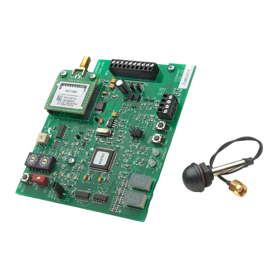
Wireless Tracker Expansion RF Board
Plug the RF board into the wireless connector and
secure board with 4 screws to the tracker expansion
board. Power transformer must connect to tracker
expansion board #33 and #34 (REQUIRED).
14
13
Multiple Wireless Tracker
12
Expansion Board Address Note:
11
NOT used for WIRELESS tracker
6
expansion boards.
When using multiple wireless tracker
5
4
expansion boards, FIRST board
Card Reader
3
address MUST start at 3 and
2
DK Prox Reader
1
continue in order thru board address
10 (up to 8 boards) if required.
First Board Address
Wiegand Access
Control Device
Existing
26, 30, 31-Bit Wiegand
Aux Power
Switch MUST be ON (1)
for board address 10.
Note: If card
reader has
Switch MUST be OFF (0)
additional
for board addresses
lighting for
3 thru 9.
outdoor use,
6 conductor, stranded with overall
separate power
shield, 18-22 gauge. 500 ft max.
must be
DO NOT use twisted pair.
provided.
T O
To #8 Com
S H
P U
To #18
Request to Exit
I T
E X
(Free Exit)
#20-Card Reader LED or Beeper Control.
(Available on certain card readers)
Wireless Tracker Expansion
Board Enclosure Options
Antenna Mount
Single Board Enclosure with
Single Board Enclosure
DK Prox Reader - P/N 1815-333
P/N 2351-080
HID Reader - P/N 1815-392
AWID Reader - P/N 1815-292
Antenna Note: This wireless system works best when the antennas are in direct-line-
of-sight with each other, in free air as high as possible above the ground. If a weak
signal occurs, a stronger antenna or a wireless repeater may be necessary to achieve a
Dome
Up to 8 wireless tracker
Antenna
strong wireless signal from each access point.
expansion boards can
(Supplied)
directly communicate with
Optional Wireless Test Range Kit: DoorKing offers a wireless test range kit (sold
wireless baseboard
RELAY 2
separately) that is used to easily test the wireless signal between the telephone entry
at the access control system.
system and any access control device(s) in desired positions BEFORE they are
See Layout and Start-Up
permantly installed. This test kit is self-contained and is easily positioned anywhere to
guide for more information.
quickly confirm wireless signal loss. P/N 1514-130 or see www.doorking.com for more
information about the wireless test range kit.
Antenna is REQUIRED.
BOARD ADDRESS
ON
RF
1
SYNC
RF
RF RANGE
LOST
0
RF ID
RF CH
RF
STRENGTH
OFF
PROGRAM
4
4
POWER
Board address 10 setting
1489-010
Starts at 3
BOARD ADDRESS
Set Board
Set Output
Address
Relay Jumper
ON
1
RF
OUTPUT
ALARM
AUX
2358-010
SECURE
RELAY
RELAY
RELAY
BOARD ADDRESS
RF
RF
CODE
CODE
CODE
DATA
STATUS
SENT
GOOD
BAD
NC
NC
NC
ON
NO
NO
NO
0
1
OFF
0
1
21
2
22
3
23
4
24
Wireless
5
25
#6-Green = Data 0
6
Connector
26
#7-White = Data 1
7
#8-Black = Common
27
8
28
#9-Red = 12 VDC Power
9
29
10
30
11
31
Ground #32
12
32
13
33
14
34
15
16
17
18
RESET
19
20
ENT
Tracker Expansion
Board Address 3
Typical Wireless Tracker
Expansion Board Wiring
Options for Access Point
NO "optional" tracker features or battery back-up wiring
shown, see manual for details.
120 S. Glasgow Avenue
Antenna Mount
Inglewood, California 90301
Door Lock Control
Electric
Relay
Jumper
strike
Maglock
Power for electric
Relay
Jumper
strike or magnetic
lock is NOT
provided by the
OR
board. Use
separate UL listed
Gate Operator Control
power supply.
Output Relay
#25 & #26
Relay
Jumper
Ground
12 GA. Wire
Board Power
16.5 VAC, 20 VA
Required
18 GA. Wire 100 ft max
16 GA. Wire 200 ft max
Multiple Wireless Tracker
Expansion Board Wiring Note:
All wireless tracker expansion
boards can be wired with desired
options for their access points like
shown on wireless tracker
expansion board address 3.
U.S.A.
Advertisement
Table of Contents

Related Manuals for DoorKing 2361-080


Summary of Contents for DoorKing 2361-080
- Page 1 (Supplied) (Supplied) system’s input power transformer is REQUIRED directly communicate with Optional Wireless Test Range Kit: DoorKing offers a wireless test range kit (sold and is reconnected to the 10-pin terminal #1-#2. wireless baseboard RELAY 2 3 2 1 separately) that is used to easily test the wireless signal between the telephone entry Antenna is REQUIRED.
- Page 2 Sets Wireless Tracker to act as Repeater HOLD TO SCAN OPERATING INSTRUCTIONS ONLY USE AS DIRECTED BY DOORKING TECH SUPPORT 0=Repeater Mode OFF 1=Repeater Mode ON Modem to Modem Connection. See PC Programmable Telephone Entry and Access Control Use “A to Z” Buttons to Locate...
Need help?
Do you have a question about the 2361-080 and is the answer not in the manual?
Questions and answers