Table of Contents
Advertisement
Quick Links
Visit website for
available languages of
QR CODE
this document.
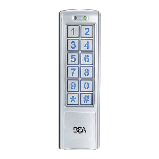
DESCRIPTION
1. Door LED
2. Mode LED
3. Matrix keypad
4. Case screw
(bottom of case)
TECHNICAL SPECIFICATIONS
Supply voltage:
Standby current:
Working current:
Max user codes:
Relock time:
Output:
Cable length:
Operating temperature:
Operating humidity:
IP rating:
Dimension:
Certification:
Backlight:
75.5892.04 KEYPADS 20201007
UNIVERSAL KEYPAD FAMILY
12 – 24 VAC/VDC
WARNING: Product will be damaged and warranty will be voided if
supply voltage exceeds 30VDC or 24VAC.
This product shall not be used with a BEA part number 1024VAC
transformer or any standard, non-regulated 24VAC transformer as the
measured voltage exceeds 24 VAC.
≤ 30 mA
≤ 160 mA
1010 ( zone 1: 1000 users, zone 2: 10 users)
0 – 99 seconds
2 relays (free of potential change-over contact)
Max. contact voltage: 42 VAC/VDC
Max. contact current: 1 A (resistive)
Max. switching power: 30 W (VDC) / 48 VA (VAC)
3 ft
-22 – 158 °F
0 – 95% (non-condensing)
IP66 (waterproof and dustproof)
10KEYPADU: 3.0" (W) x 4.7" (H) x 0.9" (D) – (76 mm x 120 mm x 22 mm)
10KEYPADUSL: 1.7" (W) x 5.9" (H) x 0.95" (D) – (44 mm x 150 mm x 24 mm)
CE, RoHS
Blue keypad illumination
Specifications are subject to change without prior notice.
All values measured in specific conditions.
Stand-alone access control keypads
10KEYPADU
1
2
3
4
10KEYPADUSL
(slimline)
1
2
3
4
Page 1 of 8
Advertisement
Table of Contents

Related Manuals for BEA 10KEYPADU


Summary of Contents for BEA 10KEYPADU
- Page 1 IP66 (waterproof and dustproof) Dimension: 10KEYPADU: 3.0” (W) x 4.7” (H) x 0.9” (D) – (76 mm x 120 mm x 22 mm) 10KEYPADUSL: 1.7” (W) x 5.9” (H) x 0.95” (D) – (44 mm x 150 mm x 24 mm)
- Page 2 READ BEFORE BEGINNING INSTALLATION/PROGRAMMING/SET-UP PRECAUTIONS ‰ Shut off all power going to header before attempting any wiring procedures. ‰ Maintain a clean and safe environment when working in public areas. ‰ Always check placement of all wiring before powering up to ensure that moving door parts will not catch any wires and cause damage to equipment.
- Page 3 WIRING Connect the wires based on the wiring diagram below. 1 Red (power +) Input DC: 12V to 24V 2 Black (power ground) Input AC: 12V to 24V 3 Brown (door magnet) 4 Orange (zone 1 exit button) 5 Yellow (zone 2 exit button) 6 Green (exit button –...
- Page 4 PROGRAMMING (cont.) GETTING STARTED DOOR MODE ENTER SETUP MODE Enter the default administration code (1234) twice (i.e. 1234 + 1234) to enter “setup” mode. Mode LED will turn red and a long beep will be heard. Press the “#” key to exit “setup” mode. Mode LED will turn green. ADMIN CODES DOOR MODE...
- Page 5 PROGRAMMING (cont.) USER CODES DOOR MODE ADD USER CODE TO ZONE 1 (must be different from admin code) Enter “setup” mode. Press the star (*) key and then “9”. Mode LED will flash red. Press “0” and then “2”. A short beep will sound. Mode LED will turn red. Enter a 3-digit number (000 –...
- Page 6 PROGRAMMING (cont.) USER CODES (cont.) DOOR MODE REMOVE ONE USER CODE Enter “setup” mode. Enter the location of the user code to be deleted (three digits). Mode LED will flash red. Press the star (*) key twice to delete. Door LED turns green. Mode LED will flash red. Press “#”...
- Page 7 OPTIONAL PROGRAMMING DOOR BELL PROGRAM A DOOR BELL Connect an external speaker (8Ω, 0.5w) to brown/white and black/white wires of this device. Press the star (*) key and the external speaker rings as a door bell. TAMPER ALARM This feature allows a built-in buzzer to activate if the keypad is removed from the wall. The alarm will stop automatically in 60 seconds or if the admin code is entered before the 60-second timeout.
- Page 8 If 3 invalid consecutive keyboard input entries occur, the keypad will be disabled for 60 seconds. BEA, INC. INSTALLATION/SERVICE COMPLIANCE EXPECTATIONS BEA Inc., the sensor manufacturer, cannot be held responsible for incorrect installations or inappropriate adjustments or the sensor/device; therefore, BEA Inc. does not guarantee any use of the sensor outside its intended purpose.
Need help?
Do you have a question about the 10KEYPADU and is the answer not in the manual?
Questions and answers