Table of Contents
Advertisement
Lillbacka Powerco Oy
P.O.B. 1
FIN-62301 Härmä, Finland
tel. + 358 6 485 4444
fax + 358 6 485 4400
OPERATING
INSTRUCTIONS
FINN-POWER
FP20
IS/AS
FP20
VS
FP110 IS/AS
FP110 VS
FP120 IS/AS
FP120 VS
FP120S IS/AS
FP120S VS
FP140 IS/AS
FP140 VS
FP140X IS/AS
FP140X VS
MANUFACTURING YEAR
RELEASED 06/00
KEEP THIS MANUAL FOR FUTURE NEEDS
THE MACHINE HAS BEEN DESIGNED FOR CRIMPING HOSE FITTINGS.
LILLBACKA POWERCO SHALL NOT BE HELD LIABLE FOR ANY PRODUCT
WHICH HAS BEEN CRIMPED ON THE MACHINE. THE MACHINE HAS BEEN
DESIGNED TO OPERATE IN ROOM TEMPERATURE, IN DRY INDOOR
CONDITIONS AND IN SUFFICIENT ILLUMINATION. USING THE MACHINE
FOR ANY OTHER PURPOSE
CONSENT FROM THE FACTORY.
¨
¨
¨
¨
¨
¨
¨
¨
¨
¨
¨
¨
IS NOT ALLOWED WITHOUT WRITTEN
Advertisement
Table of Contents

Related Manuals for Finn-Power FP20 IS/AS

Summary of Contents for Finn-Power FP20 IS/AS
- Page 1 OPERATING INSTRUCTIONS FINN-POWER ¨ FP20 IS/AS ¨ FP20 ¨ FP110 IS/AS ¨ FP110 VS ¨ FP120 IS/AS ¨ FP120 VS ¨ FP120S IS/AS ¨ FP120S VS ¨ FP140 IS/AS ¨ FP140 VS ¨ FP140X IS/AS ¨ FP140X VS MANUFACTURING YEAR...
-
Page 2: Table Of Contents
CONTENTS CONTENTS ........................... 2 GENERAL ..........................3 TRANSPORT ............................3 STORAGE............................3 MOUNTING............................3 WARNINGS ........................... 4 GENERAL ............................4 DANGER ZONES..........................4 COMMISSIONING ......................... 5 OIL FILL .............................. 5 ELECTRICAL CONNECTION......................5 QUICK FIX-PACKAGE......................... 5 OPERATION.......................... 5 CONTROL IDENTIFICATION FP20 ....................5 CONTROL IDENTIFICATION FP110, FP120, FP140 AND FP140X .......... -
Page 3: General
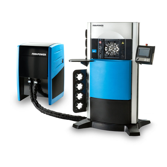
GENERAL This operation manual covers FINN-POWER FP –models of crimping machines. The model of your machine is marked on the front page. FP –models are an electrically operated hydraulic crimping machines for industrial (FP140X –model) and hydraulic hose assemblies. The crimping machines comprise a crimping head, a hydraulic unit and a base. -
Page 4: Warnings
WARNINGS General The machine is intended for professional use. It is to be operated only by a trained operator who has understood the dangers involved in the operation. Openings between the dies exceed 6 mm, thus being large enough to let fingers go between the dies and get crimped. -
Page 5: Commissioning
COMMISSIONING Oil fill Fill the oil tank to centre line of the oil level sight glass in the side plate (FP20: to centre line of the indicators in the dipstick) with hydraulic oil like Shell Tellus T 46 or equivalent. Volume of the tank is approx. 130 litres (FP20 85 litres). -
Page 6: Control Identification Fp110, Fp120, Fp140 And Fp140X
Control identification FP110, FP120, FP140 and FP140X 1. Control panel. 2. Supply disconnecting device used disconnect the machine from power supply. The device itself can be made dead only by disconnecting the plug or supply cable from the mains. 3. When the stop device is pressed, the dies will perform crimping-... -
Page 7: Control Panel Is/As
Control panel IS/AS Fp120pan.eps 1. EMERGENCY STOP Press this button in an emergency or when you for some other reason want to stop the machine quickly. Pressing the emergency stop push-button stops all machine functions. The button is released by turning it clockwise (as indicated by the arrow). - Page 8 AUTOMATIC : Crimping starts when the fitting is pressed against the stop device. The movement stops if the stop device is not adequately pressed by the fitting. It can also be stopped by withdrawing the fitting from the stop device before it is gripped by dies. If need be, dies can be opened by using retraction button 9.
-
Page 9: Control Panel Vs
Control panel VS 25.4 32-22 0.01 28.4 CONNECTOR 1 Fp120vs.eps 1. EMERGENCY STOP Press this button in an emergency or when you for some other reason want to stop the machine quickly. Pressing the emergency stop push-button stops all machine functions. The button is released by turning it clockwise (as indicated by the arrow). - Page 10 6. SEMI-AUTOMATIC CRIMPING This button starts crimping movement provided that the symbol of semi-automatic crimping is shown on the mode display. Cycle.wmf 7. CRIMPING BUTTON The dies will close when this button is pressed. The dies move until the button is released or the set crimping diameter has been reached.
-
Page 11: Test Run Is/As
17. STORING OF CRIMPING DATA Crimping data are stored in the memory for the next time to be used. It is worth while naming a fitting type to facilitate finding it again. See VS control, page 8. 18. SETUPS Set-ups of crimping delay, pressure switch, mm/inch and calibration. See VS control, page 10. 19. -
Page 12: Die Sets Fp140 And Fp140X
Die sets FP140 and FP140X Use only original Finn-Power die sets in Finn-Power crimping machines. FP 140 crimping machine is designed for crimping large fittings using FP 140 dies, but also standard dies of series 18506 can be used (4). -
Page 13: Selecting The Die Set Fp110, Fp120, Fp120S, Fp140, Fp140X
Selecting the die set FP110, FP120, FP120S, FP140, FP140X Use only original Finn-Power die sets in Finn-Power crimping machines. Refer to the fitting manufacturer's specifications for proper crimping diameter for the fitting. Each die set has its own crimping range. Follow it to assure the roundest possible crimping result. -
Page 14: Quick Change Fp110 And Fp120
Fig. 1 Fig. 2 Fig. 3 Fig.4 Qc-homma.eps QUICK CHANGE VS Die sets are stored in the storage locker and installed in the master dies with a quick change tool one set at a time. • Before installing dies, make sure that the master dies are clean. •... - Page 15 • Close the master dies completely until the pins are locked in their places (Fig. 3). • Remove the tool (Fig. 4). The dies are now ready for use • Die set is removed from the press in reverse order: close the dies, insert the tool into the die set, open the master dies and place the set back in the locker.
-
Page 16: Quick Change Fp120S
QUICK CHANGE FP120S QUICK CHANGE IS/AS Die sets are stored in the storage locker and installed in the master dies with a quick change tool one set at a time. Note! Changing the die set 18506/10 with the quick change tool is not recommendable. The die set may get broken due to the tool rod’s diameter. -
Page 17: Quick Change Fp140 And Fp140X
QUICK CHANGE VS Die sets are stored in the storage locker and installed in the master dies with a quick change tool one set at a time. Note! Changing the die set 18506/10 with the quick change tool is not recommendable. The die set may get broken due to the tool rod’s diameter. - Page 18 QC110.eps QUICK CHANGE VS Die sets are stored in the storage locker and installed in the master dies with a quick change tool one set at a time. Note! The die set no 18506/74 and larger die sets have not the quick change possibility. These dies are too thin for quick change tool holes.
-
Page 19: Change Of A Single Die Fp20, Fp110, Fp120, Fp120S
CHANGE OF A SINGLE DIE FP20, FP110, FP120, FP120S Dies can also be changed one by one with a change tool: • Select MANUAL MODE. • Open the master dies and STOP THE MOTOR. • FP120S: open the finger cover. CAUTION! ALWAYS TURN OFF THE POWER PRIOR TO INSTALLATION OR CHANGE OF DIES WITH THE CHANGE... -
Page 20: Setting The Crimping Diameter Fp20
Setting the crimping diameter FP20 SETTING THE CRIMPING DIAMETER IS/AS From crimping diameter chart on the door of the die set storage locker you can see the die numbers corresponding crimping ranges. The upper section of the chart shows corresponding dial position for each crimping diameter in the columns. -
Page 21: Setting The Crimping Diameter Fp110, Fp120, Fp120S, Fp140, Fp140X
Setting the crimping diameter FP110, FP120, FP120S, FP140, FP140X SETTING THE CRIMPING DIAMETER IS/AS From crimping diameter chart on the door of the die set storage locker you can see the numbers corresponding crimping ranges. The upper section of the chart shows the corresponding dial position each... -
Page 22: Crimping
Crimping WHEN CRIMPING A FITTING, HOLD THE HOSE FAR ENOUGH TO AVOID CRIMPING YOUR HAND! Eestaas.eps MANUAL MODE Manual mode is used during die set change, set-up and test run. 1. Select MANUAL MODE. 2. Press the start button. 3. Adjust the recommended crimping diameter. 4. - Page 23 To protect your hands from getting crimped, don't ever touch the stop device !
-
Page 24: Adjustment Of Retraction Diameter Is/As
AUTOMATIC MODE / FOOT PEDAL IS/AS foot-pdl.wmf//VS-pedal.wmf (OPTION ) As an alternative, a foot pedal can be installed in the stop device plug, eg when large fittings are crimped and more space is needed behind the machine. The foot pedal enables holding the hose assembly with both hands. -
Page 25: Greasing And Cleaning Fp20
Greasing and cleaning FP20 • Lubricate the master dies daily with pressure-proof grease like Molub Alloy OG-H or equivalent. • Close the master dies loosely before lubricating them. • Grease (1) master dies through 6 grease nipples. • Lubricate often with a small amount of grease rather than seldom with much grease. -
Page 27: Cleaning Of Fp120 Master Dies
Cleaning of FP120 master dies • Close the master dies. • Loosen four fixing screws of both upper and lower die cover and remove the die covers. • Loosen four screws of the cover plate behind the stop device and remove the cover. •... -
Page 28: Troubleshooting
Guarantee repairs shall be carried out at Lillbacka Powerco Oy, Alahärmä, Finland, or by an authorized Finn-Power service. In case guarantee repair is demanded, the customer has to prove that the machine is under guarantee. LILLBACKA POWERCO OY DO NOT WARRANT FOR ANY INCIDENTAL OR CONSEQUENTIAL DAMAGES, OR FOR ANY OTHER LOSS, DAMAGE OR EXPENSE OF ANY KIND, INCLUDING LOSS OF PROFITS. -
Page 29: Technical Data
TECHNICAL DATA Technical data FP20 FP 20 Capacity 1 ½ Crimping diameter range *) Ø (mm) 4...68 Max opening Master die shoe length Pump l/min 29/9 Max pressure Crimping force 1500 Theoretical production capacity per hour 2300 Sound pressure level dB(A) Enclosure class IP 54... -
Page 30: Technical Data Fp110, Fp120
Technical data FP110, FP120 FP110 FP120 Capacity Crimping diameter range *) Ø (mm) 4…120 4…120 Max opening Master die shoe length Pump l/min 48/12 Max pressure Crimping force 2200 2800 Theoretical production capacity per hour 1360 2400 Sound pressure level dB(A) Enclosure class IP 54... -
Page 31: Technical Data Fp120S
Technical data FP120S FP120S Capacity Crimping diameter range *) Ø (mm) 4…120 Max opening Master die shoe length Pump l/min 84/12 Max pressure Crimping force 2800 Theoretical production capacity per hour 3000 Sound pressure level dB(A) Enclosure class IP 54 Closing speed of master dies mm/s 50 Hz - 17.4 mm/s... -
Page 32: Technical Data Fp140, Fp140X
Technical data FP140, FP140X FP140 FP140X Capacity 2½ Crimping diameter range *) Ø (mm) 4...160 4...160 Max opening Master die shoe length Pump l/min 48/12 Max pressure Crimping force 3200 2500 Theoretical production capacity lkm/h 2000 1200 Sound pressure level dB(A) Enclosure class IP 54...
Need help?
Do you have a question about the FP20 IS/AS and is the answer not in the manual?
Questions and answers
FP110VS model when ever try to change data input that machine always asked add in passport.but we dont know the machine passport and where can get the passward.So can not add in data number and machine also no have movement of retraction and extraction.Please repliy for me how to solve that issues.Thank